
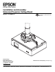
Projector Accessories User Manual


ISSUED: 01-23-07 SHEET #:055-9498-1
Visit the Peerless Web Site at www.peerlessmounts.com
4 of 10
For Technical Support Contact Peerless Mounts at 1-800-729-0307 or 708-865-8870.
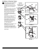
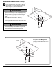
Screw extension column (sold separately)
to ceiling plate (G). Align the notch with
one of the four holes in the ceiling
plate (G) and secure extension column
with a M5 x 10 mm socket pin screw (C)
using security allen wrench (B). See
detail 1.
Screw extension column connector (I) to
extension column. Align slot in extension
column with one of the top holes in
extension column connector (I). Insert and
tighten one #10-32 x 3/8" socket pin
screw (J) through extension column
connector (I) into slot on extension
column using security allen wrench (B).
See detail 2.
Screw projector mount (A) into extension
column connector (I). Align slot in
projector mount (A) to one of the bottom
holes in extension column connector (I).
Insert and tighten one #10-32 x 3/8"
socket pin screw (J) through extension
column connector into slot in projector
mount (A) using security allen
wrench (B). See detail 3.
*NOTE: Slotted set screws (K) are used to
jam against the threads of each
connecting joint to prevent any excess
movement. Do not overtighten screws;
overtightening screws will damage threads
making it difficult to separate the products.
Skip to step 2.
DETAIL 3
SLOT
SLOT
G
I
DETAIL 2
DETAIL 1
EXTENSION
COLUMN
C
G
Installation to Extension Column
A
A
EXTENSION
COLUMN
SLOT
I
J
EXTENSION
COLUMN
SLOT
I
J
K
K
1
K*
EXTENSION
COLUMN
(ELPMBC01, UL Listed
EXT or ADJ Series)
(Sold Separately)