Before use Installation Connections Projection Useful Functions Adjustments and Setting Using the EasyMP Function Troubleshooting Maintenance Others
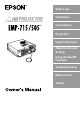
Accessory Verification Check to confirm that the following items are included in the package when removing the projector and accessories from the box. Contact your dealer if any items are found to be missing.
■ Features ● Crystal clear screen Clarity has been vastly improved. Provides crystal clear projections even in bright areas, perfect for presentation purposes. ● Wide range of display resolution Uses a newly-developed high resolution liquid crystal panel. (1024×768) ● Compact and light A compact body makes it easy for carrying around. (approximately 2.7Kg, 6 litres) ● Supports the D output port Supports digital tuners up to D4 ratings.
■ Contents Accessory Verification 1 Features 1 Contents 2 Using this manual 7 Symbol displays ...................................................................7 Power cords for use abroad .................................................7 Safety Precautions 8 Before Using This Equipment 13 Parts, Names and Operations 13 Projector .............................................................................13 Remote Control ..................................................................
Connecting up the mouse (wireless mouse function) ........ 30 Connecting the video equipment 32 In the case of composite image signals ............................. 32 In the case of S image signals ........................................... 32 In the case of component (color differential*) image signals ....................................... 33 In the case of the digital tuner's D output port ................... 34 Projecting 35 Projection 35 Preparations .........................................
Useful Functions 49 Help Function .....................................................................49 Projection Cutting 51 A/V Mute Function ..............................................................51 Freeze Function .................................................................51 Switching Image Sizes 52 Enlarging Images (E-zooming function) 54 Effect Function 55 Cursor/Stamp .....................................................................55 Box ...............................
Function description 73 Inserting the memory card 74 Viewing EasyMP files 76 Switching projected images across to EasyMP ................. 77 Operations on the file list display ....................................... 78 Operating scenarios 82 Playing back scenarios ...................................................... 82 Editing scenarios ................................................................ 83 Creating scenarios 86 Install the EasyMP Software .......................................
The projector will not switch off (after the [Power] button has been pressed) ....................107 Problems with EasyMP images ........................................107 Problems when using the EasyMP Software ...................107 Maintenance 108 Cleaning the Projector, Cleaning the Lens, Cleaning the Air Filter 108 Cleaning the projector ......................................................109 Cleaning the lens .............................................................
■ Using this manual Symbol displays A variety of picture displays have been used in this manual and on the actual product to ensure that the projector is used correctly and safely in order to prevent risks to users and other people, and to prevent damage to property. Explanations for these displays are provided below. Ensure that they are fully understood before reading this manual. Warning Displays details that may result in death or injury if ignored.
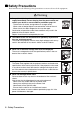
■ Safety Precautions Read and observe the following safety precautions to ensure safe use of the equipment. Warning ● If any of the following abnormalities occur, switch off the power supply immediately, remove the plug from the power socket and contact your dealer or nearest address provided at page 121. · The emission of smoke, strange odours or strange noises. · When water or foreign objects have entered the inside of the unit. · When the unit has been dropped or the case damaged.
Warning ● Never look into the lens when the power is switched on. An extremely strong light is emitted that may cause sight defects. Special attention must be paid by households with children. ● Take care when handling power plugs and power connectors. Failure to observe these instructions may result in the outbreak of fire or electric shocks. Observe the following precautions when handling power plugs and power connectors. · Never connect too many appliances to a single socket.
Caution ● Never stand on the projector or place any heavy objects on it. Failure to observe this may result in it dropping over, becoming damaged, or causing injury. ● Never place the projector on unstable surfaces, such as wobbly tables or slanted surfaces. Failure to observe this may result in it dropping over, becoming damaged, or causing injury. ● Do not place or store the projector within the reach of children’s hands.
Caution ● Always ensure that the power has been switched off, the plug has been disconnected from the power socket, and all other cables have been disconnected when moving the projector. Failure to observe this may result in the outbreak of fire or electric shocks. ● Never attempt to remove the lamp immediately after the projec- tor has been used. Wait for the projector to cool down sufficiently by leaving it for at least sixty minutes after the power supply has been switched off before attempting this.
Safety Precautions ● Using the projector outside of the permissible temperature range (+5C° to +35C°) may result in unstable display and excessive loads being placed on the fan, leading to damage to the equipment. ● Storing the projector outside of the permissible temperature range (-10C° to +60C°) may result in damage of the case. Take special care to avoid placing the equipment in direct sunlight for a long period of time. ● Do not use the projector with the lens cover still in place.
Before Using This Equipment This section provides explanations on parts and part names, and the items that should be verified before operating the remote control.
● Rear surface, Side surface 1 2 4 3 1 Power Inlet 2 Mouse/Com Port 3 USB Port 4 I/O Port ● Rear Panel 2 3 1 1 Front Foot 2 Rear Foot 3 Lamp Cover 14 - Parts, Names and Operations
● Operation panel (on top of the projector) Power Help 1 2 Source Keysto ne 3 4 Enter Select 1 [Power] button (see page 37, 40 ) Switches the power supply on and off. · Press twice to switch off the power supply. 2 [Help] button (see page 49) Displays the methods of solving problems. Press this button when trouble occurs. 3 [Source] (Enter) button (see page 38, 50) · The projected images will be switched sequentially between Computer (component) --> S-Video --> Composite Video --> EasyMP.
● I/O Ports 3 2 1 Computer/ Component Video Out In Audio S-Video 4 R 5 Audio L 6 Video Mouse/Com 7 8 1 Computer / Component Video Port Inputs computer analog image signals and AV equipment component image signals. 2 Audio In Port Inputs the sound signals from equipment connected to the Computer #1 port. Use a stereo mini-jack when making the connection. 3 Audio Out Port Outputs the projector's sound signals.
Remote Control ● Front Panel 1 2 3 4 5 Power 8 Freeze A/V Mute 5 1 6 3 4 2 9 R/C ON OFF E-Zoom Enter 10 11 7 Esc 1 Remote control light-receiving area Outputs the remote control unit’s signals. 2 Indicator Illuminated when the remote control unit signals are being output. · Light will not be emitted when the batteries are getting low or when the [R/C ON OFF] switch is set at [OFF]. 3 [Freeze] button (see page 51) Temporarily freezes the image.
10 [Enter] button (see page 31, 63) · Sets the menu item when pressed, and then moves onto the lower stage. Becomes a cursor key to select the menu items when moved up, down, left or right. · This function operates as a left-hand click on the mouse when computer images are being projected. The pointer will move when this button is moved up, down, left or right. 11 [Esc] button (see page 31, 64) · Ends the function being used. Returns to the previous stage when the menu or help text is being displayed.
● Rear Panel 1 1 Battery Cover Parts, Names and Operations - 19
Range of Remote Control Operations Depending on the distance and angle from the main unit’s light receiving area, there are cases where the remote control will not function. Ensure that the remote control is used within the following conditions: ● Operable distance: Approximately 10 metres ● Operable range: Approximately 30 degrees to the left and right Approximately 15 degrees up and down Mouse/Com Point · Ensure that the [R/C ON OFF] switch is set at [ON] when using the remote control unit.
Inserting the Remote Control Batteries The remote control batteries are inserted in accordance with the following procedure: Caution Ensure that unused batteries of the same type are used. 1 Remove the Battery Cover. Apply pressure to the clip holding the Battery Cover, and then lift it upwards. 2 Insert the batteries. Ensure that the batteries are aligned correctly with the “+” and “-“ labels on the remote control. 3 Replace the cover.
Installation This section provides an example of projector installation, and explanations on the projection distances and projection angles. ■ Installation Procedure This section provides an example of projector installation, and explanations on projection distances and angles. Caution · Do not block the ventilation outlet on the front of the projector, or the air filter (suction inlet) on the top.
Screen size and projection distance Determines the distance that the screen must be from the lens in order to obtain the required screen size. The projector’s Standard Lens is approximately a 1.2x zoom lens and the largest screen size is about 1.2 times the size of the smallest screen. Using the following table for reference purposes, install the projector so that the screen size is smaller than the screen. Screen Size Approximate Projection Distance 30-inch (61×46cm) 1.1m to 1.3m 40-inch (81×61cm) 1.
Projection angles The optimum projection screen is acquired by placing the center of the projector ’s lens and a right-angle to the screen. When viewing from the side * It is possible to move the projection position up and down with the lens shift function Mouse/Com A:B 10:Becomes 0 When viewing from the top or bottom Point Although the projection angle can be adjusted with the front foot (see page 43), there are cases where the screen will distort into a trapezoid shape.
Connections This section provides explanations on connecting the projector to computers and video equipment. ■ Connecting the projector to a computer Switch off the power supply to the projector and computer before attempting to make the connection. Eligible computers There are computers with which connections cannot be established and computers that cannot be used for projection purposes even though a connection has been established.
Condition #2: The resolution and frequency of the computer must be within the boundaries listed in the chart on the next page. Projection will not be possible if the computer does not support the output image signal resolutions and frequencies shown in the chart on the next page (there are cases where projection is possible, but vivid projection will not be possible). Confirm the image signal resolution and frequency with the computer’s instruction manual.
In the case of the mini D-Sub 15 pin Caution · Switch off the power supply to the projector and computer before attempting to make the connection. Failure to observe this may result in damage. · Confirm the shape of the cable connector and the shape of the port before making the connection. Applying excessive force when the direction or shape of the connector and port differ may result in defects and damage to the equipment.
● When the monitor port is 13w3 The Computer/Component Video port is also connected to the D-Sub 15 port with the use of the conversion cable when the 13w3 port is used for connecting the computer’s monitor port to a work station. · Connect the computer's monitor port (13w3) to the projector's Computer/Component Video port with a 13w3 <--> D-Sub 15 cable (available on the open market).
Connecting external audio equipment It is possible to enjoy dynamic sound by connecting the Audio Out port on the projector to a PA system, an active speaker system, or other speakers equipped with built-in amplifiers. External audio equipment Audio Out port Computer/ Component Video Out In Audio S-Video R Audio L Video Audio connection cable (available on the open market) Use audio connection cables available on the open market (pin plug <--> 3.5mm stereo minijack plug).
Connecting up the mouse (wireless mouse function) This enables the computer’s mouse pointer to be operated with the remote control in the same way as a wireless mouse. Connect the computer's mouse port to the projector's Mouse/Com port or USB mouse port with the mouse cable.
Perform the following mouse operations after the connection has been established: Left click - - - - - - - - - - - - - - - Press the [Enter] button. Right click - - - - - - - - - - - - - - Press the [Esc] button. Mouse pointer movement- - - Lower the remote control [Enter] button.
■ Connecting the video equipment Switch off the power supply to the projector and video equipment prior to attempting to make the connection. Point The sound for the selected image will be output. In the case of composite image signals · Connect the video port, the projector's video port and the L-Audio-R port with the RCA Audio Cable (red/white/yellow) supplied.
In the case of component (color differential*) image signals · Connect the video equipment to the projector's Computer/Component Video port with the optional component video cable (ELPKC19.) · Connect the L-Audio-R ports with the RCA audio cable supplied (red/white/yellow) to output sound from the projector's speakers.
In the case of the digital tuner's D output port · Connect the digital tuner to the projector's Computer/Component Video port with the optional D port cable (ELPKC22). · Connect the L-Audio-R ports with the RCA audio cable supplied (red/white/yellow) to output sound from the projector's speakers.
Projecting This section provides explanations on starting and ending projection, and on the basic functions for adjusting projected images. ■ Projection Images can be projected after all connections have been completed. Preparations Warning · Never look directly into the lens once the power supply has been switched on. Failure to observe this may result in the powerful light damaging eyesight. · Ensure that the Power Cord supplied is used.
4 Attach the supplied Power Cord to the projector. Check to confirm the shape of the projector’s Power Inlet and Power Connector, align the connector in the correct direction, and then insert it as far as it will go. Power Inlet Power Connector Power Cord 5 Plug the Power Plug into the power socket. The Operation Indicator will be illuminated in orange. Operation Indicator Illuminated in orange Point Button operations are not possible when the Operation Indicator is blinking in orange.
Commencing projection 1 Press the [Power] button to turn on the power supply. The Operation Indicator will begin to blink in green, and projection will be started. Power Freeze Power Help Power A/V Mute R/C ON OFF E-Zoom 2 3 5 1 Source ne 4 Power Keysto Enter Enter Select Esc Set the R/C ON OFF switch to [ON] first of all when using the remote control unit The operation indicator will change from blinking to being illuminated in green after a while.
3 Select the Port to which the connection has been made when more than one item of equipment has been connected. Press the port button connected to the computer or video equipment to switch the input source.
4 Starting projection. Switch on the power supply to the computer or video equipment. If the equipment connected is video equipment, then also press the [Playback] or [Play] buttons. The [No Signal] display will be erased, and projection will commence. Point · If [No Signal] remains displayed, check the connections once again. · Depending on the computer, there are cases when it is necessary to switch the image signal output destination with the key ( , etc.
■ Ending End projection in accordance with the following procedure. 1 Switch off the power supply to the connected equipment. 2 Press the [Power] button. A message to confirm that the power needs to be switched off will be displayed. Power Power Help Freeze Power Power Source A/V Mute Keyston R/C ON OFF E-Zoom e 3 Select 5 1 Enter 4 2 Enter Esc 3 Press the [Power] button once more.
4 Check to ascertain that the cooling down period has ended (the operation indicator will be illuminated in orange), and then remove the power plug from the socket. Operation Indicator Illuminated in orange Caution Do not remove the Power Plug from the socket when the Operation Indicator is blinking in orange. Failure to observe this may result in damage to the equipment and will speed up the period for replacing the lamp. 5 Set the R/C ON OFF switch to [OFF] when not using the remote control.
7 Attach the lens cover. 8 Rotate the zoom lever to store the lens inside the projector.
■ Adjusting the Projection Position The projector can be adjusted into the following vertical projection positions. Feet adjustments Adjusts the projection angle of the projector. 1 Lift the Foot Adjust Lever with a finger and raise the front part of the projector. The Front Foot will protrude. Foot Adjust Lever 2 Remove your finger from the Foot Adjust Lever, and then let go of the projector. 3 Rotate the lower part of the Front Foot to minutely adjust the height.
■ Adjusting the Projection Size It is possible to adjust the size of the projection and correct any trapezoid distortion. Point A function to resize the screen (see page 52) and an E-Zoom function for enlarging certain areas (see page 54) are also available. Zoom adjustment 1 Turn the zoom lever to make the adjustment (enlargement up to 1.2X is possible). Becomes smaller Becomes larger Zoom Ring The projection distance must also be adjusted when enlarging the screen.
Keystone adjustment Make the necessary adjustment when the screen has been distorted into a trapezoid with foot adjustment. 1 Press the [Keystone +, -] button on the projector to change the screen into a rectangle. Power Source Enter Help Keystone Keysto ne Select Power Source Select The corrected screen will shrink in size. Enter Help Keystone Keysto ne Select Select The corrected screen will shrink in size.
■ Picture Quality Adjustment Adjusts image focus and disturbance. Focus adjustment Aligns the focus of the image. 1 Rotate the Focus Ring to make the required adjustment. Focus Ring Point · It is not possible to align the focus if the lens is dirty or fogged over with condensation. In this event, clean the lens accordingly. (see page 109) · Correct adjustment is not possible if the installation position is out of line by between 1.1 to 13.9 meters.
Tracking adjustments (when projecting computer images) Adjusted when vertical stripes are apparent on the computer image. 1 Make the adjustment with the [Menu] - [Video] - [Tracking] function. Synchronization adjustments (when projecting computer images) Adjusted when flashing, blurring and vertical noise are apparent on the computer image. 1 Make the adjustment with the [Menu] - [Video] - [Sync.] function.
■ Introduction of Functions The functions that can be operated by pressing buttons when images are being projected are listed below. Function Outline Button Main Unit Help Displays the method of solving problems when trouble occurs. A/V Mute Temporarily mutes the image and sound. Freeze Resize E-Zoom Help 49 - A/V mute 51 Temporarily pauses image movement. - Freeze 51 Changes the size of the image. - Resize 52 Proportionally enlarges the image.
Useful Functions This section provides explanations on the effective and useful functions, such as presentations, available with this projector. ■ Useful Functions Help Function The methods of solving trouble when it occurs are divided into separate sections and explained below for use when problems arise. 1 Press the [Help] button. The help menu will be displayed.
3 Set the item. Press the [Enter] button to select the required item. Power Power Help Freeze A/V Mute R/C ON OFF E-Zoom Keyston e 5 Enter Enter 3 1 2 4 Source Enter Select Enter Esc 4 Repeat the operations explained in procedures 2 and 3 to select and set the detailed items. HELP Menu An image does not appear on the Screen. The image is blurred. The image is not displayed fully on the Screen. (cut off/too big/too small/partial) The colors of the image are not correct.
■ Projection Cutting It is possible to temporarily mute or pause images and sound. A/V Mute Function Temporarily mutes the images and sound. 1 Press the [A/V Mute] button on the remote control. The images and sound will be erased. Power Freeze A/V Mute R/C ON OFF E-Zoom A/V Mute 3 4 5 1 2 Enter Esc To resume projection, press the [A/V Mute] button once more, adjust the volume control, or display the menu.
■ Switching Image Sizes Switches between the window display and the resize display when projecting computer images. Switches between an aspect ratio of 4:3 and 16:9 when projecting video images. 1 Press the [Resize] button on the remote control. The screen size will switch. Esc Menu Help Comp EasyMP S-Video Video Auto Resize P in P Resize - Volume + ● In the case of computer images Window display: Projects with the input resolution (real display).
(Example) When the input resolution is greater than the display resolution (in the case of 1600 x 1200) Resize Display Window Display Point · The size will not be switched if the display resolution of the liquid crystal is the same as the entered resolution (1024 x 768 dots). · A certain portion of the image will not be displayed if the entered resolution is larger than the display resolution of the liquid crystal.
■ Enlarging Images (E-zooming function) The projected size will remain as it is while the image will be proportionally enlarged. 1 Press the [Zoom] button on the remote control. The size percentage will be displayed in the bottom right-hand corner to enable the image to be reduced or enlarged. The size percentage will be displayed. Power Freeze A/V Mute R/C ON OFF E-Zoom 5 1 E-Zoom 3 4 2 Enter Esc Press the [Esc] button on the remote control to cancel the setting.
■ Effect Function Effects can be added to the presentation images with the use of the [Effect1] to [Effect4] buttons on the remote control. The effects used can be amended on the [Effect] screen. (see page 66) Cursor/Stamp Imprints a stamp on the image. 1 Press the [1] button on the remote control. The Cursor/Stamp will be displayed. Power Freeze A/V Mute R/C ON OFF 1 E-Zoom 4 5 1 2 3 Enter Esc 2 Lower the [Enter] button on the remote control unit to move the position of the cursor/ stamp.
Box Draws a Box on the image. 1 Press the [2] button on the remote control. A box will be displayed. Power Freeze A/V Mute R/C ON OFF E-Zoom 2 4 5 1 2 3 Enter Esc 2 Lower the [Enter] button on the remote control unit to move the cursor to the starting position. 3 Press the [Enter] button to set the start position. 4 Lower the [Enter] button on the remote control unit to move the cursor to the ending position. 5 Press the [Enter] button to set the end position.
Spotlight Shines a spotlight on a certain part of the image. 1 Press the [3] button on the remote control. The spotlight will be displayed. Power Freeze A/V Mute R/C ON OFF E-Zoom 3 4 5 1 2 3 Enter Esc 2 Lower the [Enter] button to move the spotlight. Point · The effect function will be cancelled and the spotlight will disappear when the [Esc] or [5] button is pressed. · The mouse cannot be used when the effect function is in progress.
Bar Draws a bar line on the image. 1 Press the [4] button on the remote control. A bar will be displayed. Power Freeze A/V Mute 4 R/C ON OFF E-Zoom 3 4 2 1 5 Enter Esc 2 Press the [Enter] button to set the end position. Point · The effect function will be cancelled and the bar will disappear when the [Esc] or [5] button is pressed. · There are cases where the effect will be difficult to see depending on the color combination of the image's background and the bar.
■ P in P Function It is possible to display a video image as a sub-screen within a computer image or component video image. It is also possible to output the sound. 1 Press the [P in P] button on the remote control. An operation guide will be displayed in the top left-hand corner of the screen and the subscreen will be displayed at the top right-hand side of the screen. 2 Press the [Enter] button on the remote control to move the position of the sub-screen.
Adjustment and Settings This section provides explanations on adjusting the projector volume and on setup menu operations. ■ Volume Adjustment The volume can be amended when sound is emitted from the projector speakers. 1 Press the [Volume +, -] button on the remote control. Esc - Volume + Menu Help Comp EasyMP S-Video Video Auto Resize P in P - Volume + Point · Adjustment is not possible when no sound signals are being input.
■ Menu Configuration The menu enables the various adjustments and settings to be made. Menu items The menus are split into top menus and sub menus and consist of a hierarchy structure. Also, the image menu will differ in accordance with the input source (connected port). Top menus Sub menus (image) Video Audio Effect Setting Capture Advanced About Reset All Position Tracking Sync.
Audio menu Video Audio Effect Setting Capture Advanced About Reset All :Select Volume Tone Reset : : Effect menu Video Audio Effect Setting Capture Advanced About Reset All 0 0 Execute :Select :Enter 1 Cursor/Stamp 2 Box 3 Spotlight 4 Bar Cursor Speed Reset :Enter Setting menu Video Audio Effect Setting Capture Advanced About Reset All :Select Keystone P in P No-Sigual Msg.
■ Menu Operations The menu is operated with the remote control. Operation method 1 Press the [Menu] button on the remote control. The top menu will be displayed. Esc Menu Menu Help Comp1 EasyMP S-Video Video Auto Resize P in P - Volume + 2 Select the required item. Move the [Enter] button on the remote control up and down to select the required item. Video Audio Effect Setting Capture Advanced About Reset All 3 Set the selected item. Press the [Enter] button to determine the relevant item.
5 Select the parameter value. Move the [Enter] button to the left and right to select the required setting. Language Startup Screen Color Setting Color Temp. Rear Proj. Ceiling Reset : : : : Select [English] ON OFF RGB Setting ON OFF ON OFF Execute Point · (Enter) is attached to the rear of the sub item names that execute the parameters and continue onto the lower hierarchies. Press the [Enter] button to set this selection, and then select the parameter setting again.
Setting items Top Menu Video Sub Menu Function Default Value Position Moves the position of the image display up, down, left and right. Press the [Enter] button to perform the adjustments on the display position adjustment screen. Depends on the connection signals Tracking Adjusts vertical stripes that appear on the Computer image. Depends on the connection signals Sync. Adjusts disturbance, blurring and vertical noise that appears on the Computer image.
Top Menu Audio Effect Sub Menu Function Default Value Volume Adjusts the volume. 15 Tone Adjusts the tone 0 Reset Returns all sound menu adjustment values to the default values. Press the [Enter] button and then select [Yes] on the confirmation screen displayed. · Select [Reset All] to return all image and sound values to the default settings. (see page 68) - Cursor/Stamp Sets the shape, size, color and length of the cursor/stamp assigned to the [1] button on the remote control.
Top Menu Setting Capture Sub Menu Function Default Value Keystone Corrects screens distorted into trapezoid shapes. · The screen will be reduced in size when trapezoid correction has been performed. · The status of trapezoid correction will be recorded. Perform readjustments that match the installation position when the projection position or angle have been changed. · Reduce the sharpness if blurring occurs after trapezoid correction.
Top Menu Adva nced Sub Menu Default Value Language Sets the language with which messages are to be displayed. Press the [Enter] button and select the required language from the language selection menu displayed. English Startup Screen Displays the user logo during warm-up after the power has been switched on. · The user logo must be registered and set up before it can be amended. ON Color Setting Adjusts the color temperature (*) of the image. Color temperature: Sets the color temperature.
Image capture The image currently being displayed will be saved onto the memory card. 1 Displays the images that are to be captured. 2 Press the [Menu] button and then select [Capture] - [Image Capture]. A confirmation screen will be displayed. Image Capture User's Logo Capture Video Audio Effect Setting Capture Advanced About Reset All :Return :Select Execute Execute :Execute 3 Select [Yes] and then press the [Enter]. A screen to reconfirm the image to be registered will be displayed.
Point · A certain amount of time is required for the saving process. Do not operate the projector or connected equipment while saving is in progress. Failure to observe this may result in defects. · Images cannot be saved if the memory card has not been inserted. · Do not remove the memory card while images are being saved. · A [Capture] folder will be created on the memory card when an image has been captured, and the contents of that screen will be saved in the jpg format.
User logo registration Registers the images currently displayed as the user logo. 1 Displays the image that is to be registered as the user logo. 2 Press the [Menu] button and select [Capture]-[User’s Logo Capture]. A confirmation screen will be displayed. Image Capture User's Logo Capture Video Audio Effect Setting Capture Advanced About Reset All :Return :Select Execute Execute :Execute 3 Select [Yes] and then press the [Enter]. A screen to save will be displayed.
5 Select [Yes] and then press the [Enter]. The enlargement/reduction screen will be displayed. User's Logo Capture Do you use this image? Yes :Return :Select No :Execute 6 Select the enlargement/reduction rate and then press the [Enter]. A screen to confirm saving will be displayed. User's Logo Capture Set the zoom rate. zoom rate : 100% :Return :Select 200% 300% :Execute 7 Select [Yes] and then press the [Enter]. The image will be saved.
Using the EasyMP Function This section provides explanations on the EasyMP functions that enable the contents of memory cards to be confirmed and scenarios to be created and played back. ■ Function description The following functions are available for use with EasyMP ● Image capturing It is possible to save projected computer images and video images onto a memory card in the jpg format.
■ Inserting the memory card A memory card is required when using the EasyMP functions. ● Memory cards that can be used The following memory cards which are compatible with the Type II ATA standard can be used. · Compact flash (a PC card adapter is required during mounting) · Smart media (a PC card adapter is required during mounting) · Memory stick (a PC card adapter is required during mounting) · ATA flash card · Micro drive (a PC card adapter is required when mounting.
● Removing the card Point · Do not remove the memory card when the access lamp is illuminated in orange, or when scenarios are being played back. · Replace the memory card with a dummy card to prevent dust and dirt from entering the slot. 1 Press the button on the left-hand side of the PCMCIA card slot. The button will protrude. Access lamp 2 Press the button on the left-hand side of the PCMCIA card slot once more time. The memory card will be pushed out. Remove the card at this point.
■ Viewing EasyMP files It is possible to view the folders and files stored on the memory card with EasyMP. It is possible to display a list of files contained within the memory card inserted in the projector, and enlarge each image for confirmation purposes (preview). The preview function can be used on the following image formats: · jpg files saved with the capture function. · jpg files saved during scenario creation. · SXGA (1024 x 1280) or lower bitmap (bmp) files.
Switching projected images across to EasyMP 1 Press the [EasyMP] button on the remote control. Esc Menu Help Comp EasyMP S-Video Video Auto Resize EasyMP P in P - Volume + The projected image will switch across to a list of EasyMP files, and the contents of the memory card will be displayed. Point · A message stating [No Memory Card] will be displayed when no memory card has been inserted. The EasyMP functions cannot be used in this event.
Operations on the file list display ● Basic operations The contents of folders and files can be verified with the EasyMP file list display function. The required folder or file is selected with the [Enter] button on the remote control. 1 Align the cursor with the required folder, and then press the [Enter] button. The files contained within that folder will be displayed. Selected folder List of file names 2 Align the cursor with the required file, and then press the [Enter] button.
3 Press the [ESC] button when the preview is being displayed. The preview will end and the screen will return to the list of files. ● Functions available on the file list display screen To upper hierarchy Execute Preview Options List of files Operation guide [Execute] Shows a preview of the selected file. When a folder has been selected, the files contained within that folder will be displayed.
Point It is possible to browse through the memory card from a computer that has a USB connection when the file list is being displayed. (see page 94) ● List preview for each folder It is possible to show a preview list of files contained within a folder with the file list display. 1 Align the cursor with the required folder, and then press the [Esc] button. The folder will remain selected and the menu on the left-hand side will be enabled for use.
● Setting up the display conditions This sets up the list preview and scenario playback display conditions. 1 Align the cursor with the required folder or scenario, and then press the [Esc] button. The folder or scenario will remain selected and the menu on the left-hand side will be enabled for use. 2 Align the cursor with [Options], and then press the [Enter] button. The display condition setup screen will be displayed.
■ Operating scenarios It is possible to play back scenarios stored in the memory card. Playing back scenarios 1 Press the [EasyMP] button on the remote control to switch across to EasyMP images. The projected image will switch across to a list of EasyMP files, and the contents of the memory card will be displayed. Point · Create scenarios with the special [EasyMP Software] software beforehand on the computer in use.
Point · The playback conditions must be set at the time of creation, but the playback sequence and display/non-display parameters can be amended with the [Edit Scenario] button. (see page 83) · A confirmation message will be displayed when the [Easy/MP] button is pressed during scenario playback. Press the [Enter] button one more time to end playback. Editing scenarios 1 Align the cursor with the required scenario file on the file list display, and then press the [Esc] button.
3 Perform the following procedure to amend the sequence. (1) Align the cursor with the screen to be moved, and then press the [Enter] button. (2) Align the cursor with the place the screen is to be moved to, and then press the [Enter] button. Select the screen Select the place the screen is to be moved to 4 Perform the following procedure to prevent a selected screen from not being displayed during playback. (1) Align the cursor with the screen that is not to be displayed, and then press the [Esc] button.
5 Align the cursor with [Return] and then press the [Enter] button. The results of editing will be automatically saved in the scenario, and the screen will return to the list of files. Select [Cancel] if the details are not to be saved. Select Point The scenario will be played back with the edited conditions when [Execute] is selected.The results of editing will be automatically saved in this case.
■ Creating scenarios Scenarios are created with the special [EasyMP software] software. Install the EasyMP Software ● Operating environment Check to ascertain that this software can be operated on the computer in use. Computer Computers that operate on Windows 95/98/NT4.
Creating scenarios It is possible to create image scenarios that combine several Microsoft PowerPoint (97 or above) and image files for presentation purposes with the use of [EasyMP Software]. Point · Supports both PowerPoint 97 (SR-1 or higher) and PowerPoint 2000 (PowerPoint 2000 is recommended). · Ensure that the PowerPoint data and image files to be used have already been created. · The animation effects set up with PowerPoint will be disabled.
4 Specify the document folder to be added to the scenario with the folder window on the left. A list of files will be displayed in the file window at the bottom left-hand side of the screen. When PowerPoint files have been selected, each page will be displayed in thumbnail windows. Folder window Scenario window Thumbnail window File window Point Only thumbnails that have been created with PowerPoint 97 or above can be displayed.
6 Follow the same procedure to add required items to the scenarios. When it is necessary to switch across to other source images, such as computer images or video images, during the scenario playback, click on the right-hand mouse button at the relevant line and specify [Source Control] to insert a control line that will switch the display. The PC (computer images) will be displayed when inserted, but this can be amended with the [Cell Property] (procedure #7).
Point · It is possible to select the switching source when control lines have been inserted with the source switching function. · It is possible to set effect functions to be enabled during playback by clicking on the righthand mouse button and specifying [Cell Effect]. The effect functions are activated with buttons [1] to [5] on the remote control. · When rearranging the order of the scenario, drag the relevant lines on the scenario window.
Transmitting scenarios It is necessary to transmit created scenarios to the memory card for projection purposes. 1 Set the memory card in the computer. Set the memory card in a card adapter if necessary. 2 Specify [Scenario Option] - [Send Scenario]. The forward scenario dialog box will be displayed. 3 Specify the drive in which the memory card is set, and then click on the [OK] button. A confirmation message will be displayed. 4 Click on the [OK] button. Transmission will be started.
5 Click on the [Yes] button. Click on the [Yes] button and proceed onto the following procedures if the auto-run and repeat functions are to be set. Click on [No] if these function do not need to be set. Operations will be ended if [No] is clicked. 6 Amend the settings and then click on the [OK] button. When the auto-run parameter is to be set, select the relevant scenario from the box on the left-hand side, and then click on the [>>] button.
■ Connecting up computer with USB cables By connecting the computer and projector together with an USB cable, it is possible to view the contents of the memory card inserted in the projector from the computer. Point The computers that can be connected to the projector with a USB connection and used are restricted to those that operate on the Windows 98, Me and 2000 platforms.
3 The [Add New Hardware Wizard] and the setup program can be ended with [Cancel]. 4 Open the [Specify and Execute File Name] dialog box with [Start] - [Specify and Execute File Name]. 5 Enter [CD-ROM drive name:\USB-Driver\Win98\language\Disk1\Setup] in the [Open] field, and then click on [OK]. Installation will commence. Proceed with all subsequent procedures by observing the onscreen instructions. Point Execute [Program Files\EMP Series\Easympun.exe] to uninstall the program.
3 Select the added drive. All subsequent operations are the same as Windows file operations. Point · You cannot connect to Macintosh. Do not transfer or connent to Macintosh, as it might cause a data crush. · Projector memory card operations from a connected computer are only possible when the projector display is displayed as a file list. · Operations are not possible when the projector's memory card is being accessed. Pay attention to the following when a USB connection has been established.
Troubleshooting This section provides explanations on potential problems and the methods of taking care of them. ■ Troubleshooting When you think you have a problem, first of all check the Indicators on the projector. The projector is fitted with Operation Indicator, Lamp Indicator and Temperature Indicator to advise the user of the projector’s status.
Indicator Status Cause Recovery or Status Reference Page Blinking in Green Warm-up in progress (Not an error) · Wait for a moment. · The green lamp will stop blinking and become illuminated once the warm-up procedure has been completed. Blinking in Red Internal error Cease operations, remove the Power Plug from the socket and contact your dealer or nearest address provided at page 121 and request repairs. Extinguished The power is not switched on The power is not switched on.
Temperature Indicator Indicator Status Illuminated in Red Cause Excessive internal temperature (overheating) Recovery and Status · Use the projector within the permissible temperature range of between 5 degrees Celsius and 40 degrees Celsius. · Install the projector in a well-ventilated place and ensure that the ventilation inlet and outlet are not blocked. · Clean the Air Filter.
■ When the Indicators Provide No Help Refer to each relevant item if the following situations arise but the indicators provide no help.
● Messages ● Is the resolution of the image signal output from the computer [Not Supported] will be displayed higher than UXGA (1,600 x 1,200)? see page 26 ● Check to ensure that the mode supports the frequency of the image signals output from the computer. Refer to the computer’s instruction manual to discover how to amend the resolution and frequency of the image signals output from the computer.
● Have displayable files be saved onto the memory card? A message stating [No displayable files] will be displayed. The files that can be displayed with EasyMP are scenario files (.sit), jpeg files (.jpg) and bitmap files (,bmp). Other files will not be recognized. · Although files with a log extension of .jpeg are recognized on the Widows platform as jpeg files, they are not recognized by EasyMP. Amend the log extension to .JPG or .jpg.
● Is the memory card full? If there is no more space left to save files, increase the capacity of the memory card by deleting other files. A message stating [File cannot be saved] will be displayed. ● Was an image captured while the computer was connected with a USB connection? It is not possible to capture images when a USB connection is in use. Disconnect the USB cable. A message stating [Capture failed] will be displayed.
The image is unclear ● Has the lens been stored in the projector? ● · The screen is blurred. · Focus can only be attained in certain areas. ● ● ● ● ● ● ● ● Images will be out of focus if the position of the zoom lever is outside of the [W] to [T] range. Ensure that the lever is set within the [W] to [T] range.
● Has the cable been connected correctly? see page 25, 32 ● Is the selected resolution correct? · The image is disturbed. · Noise appears ● ● ● ● Align the computer with the signals supported by the projector. Refer to the computer’s instruction manual for details on how to amend the signals. see page 26 Have the [Synchronization *, Tracking *, Display Position] settings been correctly adjusted. Press the [Auto] button to make the adjustments.
The image color is bad ● Has the image brightness been correctly adjusted? see page 65 ● Have the cables been connected correctly? see page 25, 32 ● Has the contrast been correctly adjusted? see page 65 ● Has the color setting been correctly adjusted? see page 68 ● Have the color density and tint been correctly adjusted? (The display on the computer monitor or the liquid crystal screen will not always match up with the tint of the image, but this is not an abnormality.
No sound ● Has the sound input been connected correctly? see page 28, 32 ● Has the image for which sound is required been selected? see page 38 ● Has the volume been set to the minimum? see page 60 ● Is sound being emitted from connected equipment? Confirm the sound from connected equipment, etc. Has the volume been turned right down? ● Has the [A/V Mute] function been left on? There is a possibility that the [A/V Mute] mode is in effect.
The projector will not switch off (after the [Power] button has been pressed) ● Is the Operation Indicator illuminated in orange? The projector has been designed so that the Operation Indicator is not extinguished even when the power has been switched off. The Operation Indicator will be extinguished when the Power Plug has been disconnected from the socket. ● The fan will not cease operations.
Maintenance This section provides explanations on taking care of the projector, replacing consumable items and other maintenance procedures. ■ Cleaning the Projector, Cleaning the Lens, Cleaning the Air Filter Clean the projector if it becomes soiled or if the quality of the projected images deteriorate. Please clean the air filter about every 100 hours of operation. Warning · Personnel other than qualified servicemen must never open the projector.
Cleaning the projector · Gently wipe the soiled parts of the projector with a soft cloth. · When the soiling is severe, wipe the area with a cloth moistened with a medium-strenth cleaning agent diluted with water, and then gently wipe it with a dry cloth. Never use wax, Benzene, thinner or other active agents. Failure to observe this may result in damage or paint peeling from the casing. Cleaning the lens Clean the lens with an air-blower (available on the open market) and special lens cleaning paper.
■ Replacing the Air Filter Replacement method 1 Switch off the power supply, allow the projector to cool down, and then disconnect the Power Cord. The amount of time required for the projector to cool down will depend on the surrounding temperature. 2 Raise the air filter with a screwdriver or similar object to remove it. Point Ensure that the projector is stood on its end when replacing the Air Filter to prevent the dirt and dust from penetrating inside. 3 Set a new Air Filter in place.
■ Replacing the Lamp Replace the lamp at the following times (model number: ELPLP14). When a message stating [Lamp Replace] is displayed for thirty seconds after the start of projection Lamp Replace When the lamp indicator is blinking in orange The lamp indicator will blink in orange.
Replacement method 1 Switch off the power supply, allow the projector to cool down*, and then disconnect the Power Cord. The amount of time required for the projector to cool down will depend on the surrounding temperature. 2 Wait until the lamp has cooled down sufficiently, and then remove the lamp cover. · Approximately one hour is required for the lamp to cool down sufficiently. · Loosen and remove the screw holding the fan in place. 3 Withdraw the lamp.
5 Attach the lamp cover. Align the direction, insert the fan, and then secure it in place with the one screw. Point · Attach the lamp firmly. A safety mechanism on the projector switches off the power automatically when the lamp cover has been removed. The power will not be reinstated unless the lamp and lamp cover are set firmly in place. · A replacement Air Filter is packaged with the replacement lamp. Replace the Air Filter at the same time as replacing the lamp.
Others This section provides explanations on optional items and after service care, as well as providing details on specifications, terminology and other technical information. ■ Optional Parts The following optional parts are available for purchase in accordance with your needs. MAC Adapter Set ELPAP01 Image Presentation Camera (XGA) ELPDC02 Computer Cable ELPKC02 VGA-HD15 PC Cable (3.0m) ELPKC09 Component Video Cable (D-Sub15/3BNC, 3.
■ Transportation The projector contains many glass and precision parts. Ensure that the following precautions are observed to prevent the projector from being damaged by impact during transportation. ● When sending the projector to the manufacturer for repairs, etc. · Use the box in which the projector was packed at the time of purchase.
■ Terminology This section provides simple explanations for the terminology used within the manual, items for which explanations are not available, and other complex processes. A/V Mute Temporarily erases the image and sound. The sound and image can be muted by pressing the [A/V Mute] button on the projector. Press the [A/V Mute] button once again or adjust the volume or display the menu to cancel the mute mode.
Contrast By strengthening or weakening the tone of the colors, it is possible to project characters and pictures more clearly and attain a softer tint. This is known as contrast adjustment. Tracking Outputs computer signals at a pre-determined frequency. The image will not be projected clearly unless this frequency is aligned with the frequency of the projector. Aligning the signal frequency is known as tracking.
■ Specifications Product Name Multi-Media Projector Model EMP-715/505 External Dimensions Width 267 × Height 72 × Depth 213 mm(excluding the lens and feet) Panel Size 0.9-inch (Width 18.5mm × Height 13.9mm × Corner-to-corner 23.
■ Check Sheet Kindly take a copy of the check sheet and fill out the relevant items before contacting us in order to provide us with details on the systems of the trouble that has occurred with your projector.
● Sound Inquiry details ❒ ❒ ❒ ❒ Menu No sound can be heard The volume is too low The sound breaks up A different sound is emitted ❒ The menu is displayed Sound ❒ Volume( ) EMP Serial number Purchasing time Year, month Connector ❒ Is it plugged in firmly? ❒ Is the sound emitted when connected to external speakers? ❒ Computer Win • MAC • EWS Manufacturer's name( Model ( ) ❒ Is the sound set for output? ) ❒ Video equipment Video, DVD, camera Manufacturer's name ( ) Model( ) ❒ Audio cable ❒ A/V cable ❒
■ World-Wide Warranty Terms This product includes a world-wide warranty, which allows the equipment to be repaired in more than forty-five countries of the world. Note that product is not covered by the terms of warranty stated here, but by the terms of warranty laid out on the warranty card supplied when the equipment is purchased in each relevent country.
AUSTRIA : EPSON Support Center Austria Tech. Help Desk: 00491805 235470 Web Address: http://www.epson.at BELGIUM : EPSON Support Center BeNeLux Tech. Help Desk: 032 70222082 Web Address: http://www.epson.be BULGARIA : PROSOFT 6. AI Jendov Str. BG-1113 Sofia Tel: 00359.2.730.231 Fax: 00359.2.9711049 E-mail: Prosoft@internet-BG.BG FINLAND : Tech. Help Desk: 0800.523010 (note. Some geographical areas excluded) FRANCE : LUXEMBURG : EPSON Support Center BeNeLux Tech.
DENMARK : Tech. Help Desk: 80881127 SLOVENIA : ITALY : SLOVAKIA : EPSON Italia s.p.a. Print Trade spol. s.r.o. Assistenza e Servizio Clienti Viale F. Lli Casiragi, 427 20099 Sesto San Giovanni (MI) Tech. Help Desk: 02.29400341 Web Address: http://www.epson.it Cajkovskeho 8 SK-98401 Lucenec Tel: 00421.863.4331517 Fax: 00421.863.4325656 E-mail: Prntrd@lc.psg.SK Web Address: http://www.printtrade.sk SWITZERLAND : UNITED KINGDOM : Repro Ljubljana d.o.o. EXCOM Service AG EPSON (UK) Ltd.
ARGENTINA : CHILE : PERU : Epson Argentina S.A. Epson Chile S.A. Epson Peru S.A. Avenida Belgrano 964/970 (1192), Buenos Aires Tel: (54 11) 4346-0300 Web Address: http://www.epson.com.ar La Concepcion 322 Providencia, Santiago Tel: (562) 236-2543 Web Address: http://www.epson.cl Av. Del Parque Sur #400 San Isidro, Lima, Peru Tel: (51 1) 224-2336 Web Address: http://www.epson.com BRAZIL : COLOMBIA : VENEZUELA : Epson Do Brasil Ltda. Epson Colombia Ltda. Epson Venezuela S.A. Av.
■ Index Numerics 13w3 28 A A/V Mute 67 A/V Mute button 17 A/V Mute Function 51 About 68 About menu 62 Adjusting the Projection Position 43 Adjusting the Projection Size 44 Advanced 68 Advanced menu 62 Audio 66 Audio In Port 16 Audio menu 62 Auto adjustment 46 Auto button 18 Auto Setup 65 B Bar 58, 66 Battery Cover 19, 21 Box 56, 66 Brightness 65 C Cancelling effects 58 Capture 67 Capture menu 62 Ceiling 68 Check Sheet 119 Cleaning the Air Filter 109 Cleaning the Projector, Cleaning the Lens, Cleaning the
G Gamma 65 H Help button 15 Help Function 49 I I/O Terminal 14 Image capture 67 image signals 33 Indicator 17 Installation Procedure 22 K Keystone 67 Keystone button 15 L Lamp Cover 14 Lamp Indicator 13, 97 Language 68 Left click 31 Lens Cover 13, 35 lens cover 42 Light button 17 M Maximum Sound Output 118 Menu button 63 Menu Configuration 61 Menu Operations 63 mini D-Sub 15 pin 27 Mouse/Com Port 16, 30 Operation Indicator 13, 36, 96 Operation Panel 13, 15 Optional Parts 114 overheating 98 P P in P b
Sound connection 28 Source 38 Speaker 13 Specifications 118 Spotlight 57, 66 Stamp 55 Startup Screen 68 sub menus 61 S-Video button 18 S-Video Port 16 S-Video port 32 Symbol displays 7 Sync.
DECLARATION of CONFORMITY according to ISO/IEC Guide 22 and EN 45014 Manufacturer : SEIKO EPSON CORPORATION Address : 3-5, Owa 3-chome, Suwa-shi, Nagano-ken 392-8502 Japan Representative : EPSON EUROPE B. V.
DECLARATION of CONFORMITY According to 47CFR, Part 2 and 15 for Class B Personal Computers and Peripherals; and/or CPU Boards and Power Supplies used with Class B Personal Computers We : EPSON AMERICA, INC. Located at : MS: 3-13 3840 Kilroy Airport Way Long Beach, CA 90806-2469 Telephone: (562) 290- 5254 Declare under sole responsibility that the product identified herein, complies with 47CFR Part 2 and 15 of the FCC rules as a Class B digital device.
FCC Compliance Statement For United States Users This equipment has been tested and found to comply with the limits for a Class B digital device, pursuant to Part 15 of the FCC Rules. These limits are designed to provide reasonable protection against harmful interference in a residential installation. This equipment generates, uses, and can radiate radio frequency energy and, if not installed and used in accordance with the instructions, may cause harmful interference to radio or television reception.
All rights reserved. No part of this publication may be reproduced, stored in a retrieval system, or transmitted in any form or by any means, electronic, mechanical, photocopying, recording, or otherwise, without the prior written permission of SEIKO EPSON CORPORATION. No patent liability is assumed with respect to the use of the information contained herein. Neither is any liability assumed for damages resulting from the use of the information contained herein.
Printed in Japan 90010652