Installation Guide
Copyright Notice All rights reserved. No part of this publication may be reproduced, stored in a retrieval system, or transmitted in any form or by any means, electronic, mechanical, photocopying, recording, or otherwise, without the prior written permission of Seiko Epson Corporation. The information contained herein is designed only for use with this Epson product. Epson is not responsible for any use of this information as applied to other equipment.
Contents Introduction . . . . . . . . . . . . . . . . . . . . . . . . . . . . . . . . . . . . . . . . . . . . . . . . . . . . . . . . . . . . . . . . . . . . . . 5 Important Safety Instructions . . . . . . . . . . . . . . . . . . . . . . . . . . . . . . . . . . . . . . . . . . . . . . . . . . . . . 6 Parts List . . . . . . . . . . . . . . . . . . . . . . . . . . . . . . . . . . . . . . . . . . . . . . . . . . . . . . . . . . . . . . . . . . . . 10 Included Cables . . . . . . . . . . . . . . . . . . . . . .
Adjusting the Sound . . . . . . . . . . . . . . . . . . . . . . . . . . . . . . . . . . . . . . . . . . . . . . . . . . . . . . . . . . . . . . 58 Set the Boundary Control Switch . . . . . . . . . . . . . . . . . . . . . . . . . . . . . . . . . . . . . . . . . . . . . . . . . . 58 Set the Speaker Distance. . . . . . . . . . . . . . . . . . . . . . . . . . . . . . . . . . . . . . . . . . . . . . . . . . . . . . . . . 59 Equalize the Speaker Output . . . . . . . . . . . . . . . . . . . . . . . . . . . . . . .
Introduction The Ensemble HD home cinema system by Epson® includes everything that’s needed to set up a home theater. TM • ® Projector – The PowerLite projector provides high-definition, theater-quality video. The projector is housed in the integrated speaker enclosure, which contains the rear surround speakers, part of the home theater’s 5.1-channel audio system. The system comes with either the PowerLite Home Cinema 1080 or the PowerLite Home Cinema 720.
Important Safety Instructions To reduce the risk of electric shock, do not remove the cover (or back). No user serviceable parts inside. Refer servicing to qualified personnel. CAUTION: CAUTION: These servicing instructions are for use by qualified service personnel only. To reduce the risk of electric shock, do not perform any servicing other than that contained in the operating instructions unless you are qualified to do so.
13. Refer all servicing to qualified service personnel. Servicing is required when the apparatus has been damaged in any way, such as power-supply cord or plug is damaged, liquid has been spilled or objects have fallen into the apparatus, the apparatus has been exposed to rain or moisture, does not operate normally, or has been dropped. Additional Safety Instructions • Safety measures must be practiced at all times during the installation of the home theater system.
routing wires. Personal injury and/or damage to the equipment could result from dropping or mishandling it. • Make sure the screen is completely closed before placing it on or lifting it off the wall or ceiling mount. • Do not route the included power cables through the wall or ceiling. They are not rated for this purpose. Deliberate mis-installation could result in fire or other safety hazards.
• Do not overload wall outlets, extension cords, or integral convenience receptacles as this can result in a risk of fire or electric shock. • Keep the system components free from moisture, water, and dust. • Do not let insecticides, benzene, or thinner come in contact with any components of the system. • Never push objects of any kind through openings in the system components as they may touch dangerous voltage points or short-out parts that could result in a fire or electric shock.
Parts List Before starting, make sure you have all the boxes listed below. Tip Leave all the items in their containers until the instructions tell you to remove them. That way, you can easily find the parts you’ll need at different points during the installation.
Included Cables All required cables are included, as listed below: Cable connection Cable name Length From power outlet to subwoofer Main power cord 6 feet (1.8 m) From AV equipment to screen AC power cable * Speaker cable * HDMI video cable ** Control cable with mini-jack connector ** 33 feet (10 m) * Connects from subwoofer to screen. ** Connects from AV controller to screen.
Where To Get Help Epson provides the following technical support services for your home theater system. Note Epson strongly recommends that the home theater system be installed by a professional audio/video installer or other qualified professional. Epson cannot provide advice concerning construction practices or building codes in your area. Internet Support Visit Epson’s support website at epson.com/support and select your product for solutions to common problems.
Planning the Installation Here are the basic steps required to install the home theater system. Allow at least 4 to 6 hours to complete the installation. Be sure to read the following pages before starting. Note Epson strongly recommends that the home theater system be installed by a professional audio/video installer or other qualified professional. Epson cannot provide advice concerning construction practices or building codes in your area. Screen image 1 Plan the screen location and room layout.
Required Tools The Ensemble HD home theater system should be installed by a professional audio/video installer or other qualified professional.
Keep the following in mind: • Your seating area should allow for a comfortable viewing distance to the screen. The seats should be arranged to allow viewing from approximately 12 to 16 feet away (3.7 to 4.9 m). • For best surround-sound performance, the projector (with its rear surround speakers) should be placed as far behind the seating area as possible.
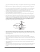
Locating the Projector Once you know where the screen will go, you can determine the location of the projector. For the best sound quality from the rear surround speakers, you should mount the projector as far behind the seating area as possible. In a typical installation with the screen mounted near the ceiling, you can place the projector mount up to about 19 feet (5.8 m) from the screen (limited by the length of the cables).
There are two locations where you can use the tracks, as shown. The track going from the AV equipment to the screen can approach the screen from either the left or right side, depending on where the AV equipment is located. (The left side is preferred so that excess cable can be stored inside the right side of the screen.) The track going from the screen to the projector looks best when aligned with the middle of the screen, as shown.
Cable Connections Refer to the diagram below for an overview of how all the Ensemble HD components are connected: Projector Control cable Rear surround speakers HDMI cable 110 VAC power cable Speaker cable Motorized screen HDMI repeater and power supply L/C/R speaker connectors HDMI cable Control cable Speaker cable AV data cable BASS CONTOUR CONTROL FREQ 61 47 LEVEL 82 PWR ON MODE 98 99 SUB OUT 110 VAC power cables AV Controller Subwoofer Main power cord 18
Installing the Screen Follow these steps to attach the screen’s mounting assembly to your wall or ceiling, connect the cables to the screen, and lift the screen onto the mounting brackets. Unpack the Screen and Speaker Grilles 1 Unpack the screen and related hardware from the long container (box #4).
Note The box also contains the wire management tracks and related pieces shown below. It is advisable to keep these parts together until they’re needed on page 43. 8-foot-long tracks (6 pieces) 2 Wall-to-ceiling transition (2 sets) Corner connector (3 sets) Seam cover (20 pieces) Drywall screws (100 pieces) Unpack the speaker grilles from box #7. Note that two screws are packed with each grille. You will use them to attach the grille to the screen, as described in the next section.
Attach the Mounting Assembly to the Wall (Option 1) Follow these steps if you want to mount the screen on your wall. If you prefer to hang it from the ceiling, see “Attach the Mounting Assembly to the Ceiling (Option 2)”on page 24. Note These steps describe how to attach the screen to a wall with wooden studs. If you have a solid concrete wall, you can also attach it using the included concrete anchor bolts.
Mark the wall as shown below: Distance from ceiling... ...plus 3 inches Do not install alignment bar (not shown) above this line 4 Hold the mounting assembly against the wall and use a stud finder to locate two studs, one near each end of the alignment bar. Studs are normally spaced 16 inches on center. Mark the exact center of each stud. Warning You must find the exact center of each stud, or you won’t be able to attach the screen securely. Note The middle bracket doesn’t have to be attached to a stud.
5 Use a level to make sure the alignment bar isn’t tilted to one side. Align one of the end brackets with the stud you marked on the wall and attach it with two wood screws. Caution The bar must be level, or the screen will not deploy properly. A slight tilt may cause screen failure over time. Attach bracket to stud in wall Loosen screw to slide bracket on alignment bar 6 Attach the bracket at the opposite end of the alignment bar.
Attach the Mounting Assembly to the Ceiling (Option 2) You can hang the screen from a flat (not sloped) ceiling. If your ceiling has wooden joists, this option is possible only if the joists run toward the screen. If they run across the width of your room, you won’t be able to hang the screen safely from the ceiling. Also, make sure your ceiling is level before starting—if it isn’t, the screen will not hang properly. Note These steps describe how to attach the screen to a ceiling with wooden joists.
7 Tighten the screw on the face of each bracket to secure it to the alignment bar. 8 Determine where the middle of the screen will be. Then position the middle bracket so it’s aligned with the middle of the screen. The set screw in the middle of the screen must engage with the bracket. 9 If the middle bracket aligns with the center of a joist (see diagram below), attach it to the ceiling with two wood screws; otherwise use two Toggler anchors.
Connect the Cables to the Screen Before lifting the screen onto the mounting brackets, you’ll need to connect the cables to the screen. This is best done with the screen resting right-side-up on a carpeted floor or other soft surface. All the cables are grouped together by length. To avoid mixing up the cables, unpack them in the order they’re called for in the instructions.
4 Connect one end of the Control Cable to the control port, as shown below. To AV controller (do not connect yet) 5 Connect the individual connectors of the Speaker Cable to the corresponding connectors inside the screen. Match up the L (Left), C (Center), and R (Right) labels on the connectors. Leave the 4-pin connector unconnected for now (it will go to the projector).
8 Connect AC CABLE 3 to the AC output connector, as shown below. To projector (do not connect yet) To HDMI repeater 9 Locate the 7M KIT packed in box #3. The 23-foot (7-meter) cables included in this kit connect the projector to the screen. The kit also includes a video cable connector (HDMI repeater) and its power supply. 10 Connect power supply for the HDMI repeater to the power cable, as shown above.
13 Connect the Video Cable to the OUTPUT end of the HDMI repeater. Then connect the INPUT end of the HDMI repeater to the other video cable that you already placed near the screen (see page 27). To AV controller To projector input output 14 Connect the power supply for the HDMI repeater to the power inlet on the repeater. 15 Secure the cables inside the screen under the molded plastic cable covers. Flex the covers upward to lift them slightly, then slip the cables underneath.
2 With a second person’s help, lift the screen onto the three mounting brackets. The screen must hook into the groove on all three brackets. Tilt the screen back slightly when lowering it onto the brackets. Warning You must have a second person’s help when lifting the screen. Use ladders as necessary to reach a high location. Caution Do not hold the screen by the speaker grilles, which are fragile and can be easily dented. Lift the screen only from the bottom and by holding the plastic covers on each end.
Installing the Projector Unpack the projector ceiling mount from box #1. The mount includes the following hardware: • Ceiling plate • Mounting bracket • Extension arm (optional) • Mounting hardware and Allen wrench The optional extension arm can be used to reduce the vertical distance between the projector lens and the screen—for example, in installations with high or sloped ceilings.
Position the Ceiling Mount This section explains how to determine where the ceiling mount will be installed. Follow these steps to mark and drill holes for attaching the mount. Determine how far back you want to place the projector from the screen. The center of the ceiling mount should be located about 10 to 19 feet (3 to 5.8 m) from the wall on which the screen is mounted (or from the back of the screen, if it’s hung from the ceiling).
Next, determine the left-right position of the ceiling mount in relation to the screen. Mark the ceiling at a point aligned as closely as possible to the middle of the screen. Note Try to keep the lens within 8 inches left or right of the screen’s center. You can then use the horizontal lens shift dial to position the image on the screen. If you position it off-center by more than that, the vertical (up/down) lens shift adjustment will be limited.
3 Determine whether the joists in your ceiling run parallel to the screen or toward the screen, as shown below. Use a stud finder if necessary. 4 Locate two adjacent joists on opposite sides of the location where you plan to install the mount. Mark the exact center of one joist, to indicate where you will attach the ceiling plate. Then measure 16.25 inches to the second joist and mark it as shown. Warning Use a stud finder to locate the center of the first joist.
5 Hold the ceiling plate in place over the planned mounting location to ensure that the holes in the plate line up with the marks you drew on the ceiling. 6 Take the plate down and drill the two marked holes (you’ll drill the remaining holes after attaching the plate). 7 Continue to the next section if you plan to use the extension arm. Otherwise, continue to “Install the Ceiling Mount” on page 37.
3 Insert the extension arm into the piece shown below. Make sure the set screws in the extension arm are turned in all the way, or you won’t be able to insert the arm. Note Do not re-insert the bolts you removed in step 2. You will do this later when you attach the mounting bracket to the ceiling plate, as described in the next section. 4 Insert the extension arm into the lower plate and fasten it with the bolt you removed in step 1. 5 The mounting bracket with the extension arm is now assembled.
Install the Ceiling Mount 1 To install the mounting bracket, first remove the piece shown below. Take out the two bolts to remove it. Note If you attached the extension arm as described in the previous section, skip to step 2. Remove this piece 2 Attach the removed piece of the mounting bracket to the ceiling plate, as shown below. Use the included fastening plate and bolts to attach it. The fastening plate goes on the recessed side of the ceiling plate.
4 Attach the ceiling plate to the ceiling at the pre-drilled location. Use two of the included wood screws. 5 Drill the remaining four holes with the ceiling plate in place. Finish securing it with the remaining wood screws. Mount the Projector Before mounting the projector, you may find it easier to perform the following tasks first: • Plug in the projector and turn it on, then invert the image so it’s oriented correctly when the projector is hung from the ceiling.
4 Remove the bottom and rear covers from the projector enclosure. • Remove the bottom cover by sliding it off toward the front. (The cover is held in place with clips, which may be tight.) • Remove the rear cover by pressing inward on one side to release the catch. While pressing inward, pull backward on the same side to separate the cover from the enclosure. Repeat on the opposite side.
6 Turn the projector upside-down and slide it into the enclosure. Make sure the projector ports are on the same side as the speaker cables, as shown. Attach the projector with the four screws and washers as shown. 7 Check the part of the ceiling mount where you will attach the projector (the round plate on the bottom). Make sure the three thumb screws are loosened enough so that they don’t protrude through the bottom of the round plate.
9 Lift the projector up to the ceiling mount, holding it with the lens facing backward (away from the screen). Warning Use a ladder that is tall enough for you to see over the top of the projector when mounting it. You must be able to see the ceiling mount to handle the projector safely. You could lose your balance if you hold the projector over your head when mounting it. 10 Engage the projector with the ceiling mount, then rotate it 180 degrees so it faces toward the screen.
12 Make sure the projector is not tilted sideways. If the projector is tilted to one side, loosen the set screw on the front of the mounting bracket (shown below) and adjust the projector so it’s level. Tighten the set screw when done. 13 If you’ve used the extension arm, make sure the projector is not tilted down toward the screen. Loosen the set screws on the side of the arm and adjust it so it’s straight. Tighten the set screws when done.
Connecting and Routing the Cables Follow the instructions in this section to install the wire management tracks on your wall and ceiling, place the cables in the tracks, and connect the cables to your equipment. Note If you want, you can route the video cable, speaker cable, and control cable through your wall and ceiling instead of using the wire management tracks. These cables are plenum-rated (fire retardant), so they can be routed through a wall, an attic, or the space above your ceiling.
Install the Tracks and Connector Pieces 1 Plan your layout of the wire management system, referring to the illustration below. If you want to connect two 8-foot tracks together (end-to-end), use a seam cover where the tracks meet. Use the small connector pieces to turn corners and transition from the wall to the ceiling. Use a hacksaw to cut the tracks to desired lengths. Tip When using a hacksaw, cut the plastic slowly to maintain smooth edges.
4 Starting from the screen, press the cables into their respective channels in each track. Use a blunt tool, such as a screwdriver handle, to press the cables into place. Press the smaller cables in first, and the large cable last. Note The individual channels inside the track are sized differently. Be sure to place the correct cable in each channel. If you’re unsure, check the colored dot at the end of the cable and match it to the color inside the track.
2 Connect the following three cables to the projector: • Video cable • AC cable • Control cable Video cable (HDMI port) Control cable (RS-232C port) AC cable Power switch 3 Flip the power switch to the on position (indicated by the symbol). 4 Connect the speaker cable to the connectors for the left and right speakers in the projector enclosure. Match up the R (right) and L (left) labels on the connectors.
3 Connect the following two cables from the screen to the subwoofer: • Speaker cable (connect it to the SPK OUT connector) • AC cable (connect it to either AC OUTPUT connector) BASS CONTOUR CONTROL FREQ 61 47 LEVEL 82 PWR ON MODE 98 99 SUB OUT Connect speaker cable here Connect AC cable to either outlet MASTER POWER 4 Connect the following two cables from the screen to the AV controller: • Video cable (connect to HDMI OUT port) • Control cable, with 3.
5 Locate the 16-foot (5-meter) AV data cable (packed in box #3). Connect it from the 5.1CH OUT port on the AV controller to the INPUT port on the subwoofer. Connect these ports with the AV data cable BASS CONTOUR CONTROL FREQ 61 47 LEVEL 82 PWR ON MODE 98 99 Connect power cord to outlet on subwoofer SUB OUT MASTER POWER 6 Connect the AV controller’s power cable to the remaining AC OUTPUT connector on the subwoofer. You can also connect it directly to a grounded power outlet in your home.
Assembling the Subwoofer Stand If you like, you can use the included stand to store the subwoofer and AV controller. It also provides space for storing additional components. Place AV controller or other components here Place subwoofer here Follow these instructions to assemble the stand: 1 Unpack the stand from box #6. 2 Locate the base and set it flat on the floor or a worktable. You should see only the four holes for the rubber feet (the six holes underneath the base should face downward).
4 To connect the upper and middle shelves, first insert pins as shown. Then use the nuts and bolts to connect the shelves in the same way as for the base. Note The pins are not optional, but help reinforce the shelves. You must insert them first, before inserting the bolts. You may find it easier to connect the shelves if you tilt the stand back. Insert pins 5 Insert the rubber feet into the holes in the base. Note The feet help to isolate vibration from the subwoofer.
Adjusting the Image Follow the steps in this section to adjust your system and make it ready for use. Insert Batteries Insert the included batteries into the remote controls for both the projector and the Ensemble HD system, as shown below. Note The projector remote control is used only to make initial adjustments to the projector, but it should be saved in case it’s needed after installation.
If you haven’t already adjusted the projector settings, the image will be upside-down or you may see a No Signal message. This is normal. You will adjust these settings in “Adjusting the Projector Settings” on page 56. If the system doesn’t turn on, check the following: 5 • If the system is not receiving power, make sure your electrical outlet is working and isn’t controlled by a wall switch or timer. • Check that the power cords on the back of the subwoofer are connected securely.
4 Use the following commands to raise and lower the screen, and to stop it at the desired position: • S-UP to raise the screen • S-DWN to lower the screen When the screen comes to a stop, press S-DWN again to lower it beyond the current stop-position. You can bring it down as far as the maximum length preset by the factory, or 64 inches. • S-STP to stop the screen 5 Once the screen is positioned where you want it, press S-SET to set the screen position. 6 Press S-UP to raise the screen fully.
3 Use the horizontal and vertical lens shift dials to position the image on the screen. Left/right adjustment Up/down adjustment Note If the image is not positioned correctly, do not angle the projector toward the screen. Instead, face the projector straight ahead, keeping it level, and use the lens shift dials to move the image.
Incline Adjustment With the Optional Extension Arm You must have already installed the extension arm (page 35) to be able to perform this adjustment. If you’re not using the extension arm, or if the image already fits on the screen without the projector being tilted down toward it, skip this section and continue with “Adjusting the Projector Settings” on page 56.
Adjusting the Projector Settings Projector remote control Use the projector’s remote control to adjust the following settings. Note If you need to restore the projector’s factory settings, open the Reset menu and select Reset All. 1 Press the HDMI button on the remote control to select HDMI as the source. 2 Press the Menu button on the remote control. You see the main menu screen: 3 Open the Settings menu (press the d button to highlight Settings, then press Select).
Set the Color Mode Set the projector’s Color Mode to quickly optimize the image for the current lighting conditions. For example, you might select Living Room for watching movies in the daytime with the curtains closed, and Theatre for watching movies at night. Note Color Mode adjusts brightness, contrast, and color. Image settings can be further customized using the Video menu in the Ensemble HD menu system. See the User’s Guide for details. 1 Press the Color Mode button on the projector remote control.
Adjusting the Sound Follow the steps in this section to optimize sound for your home theater. Set the Boundary Control Switch Set the BOUNDARY CONTROL switch on the back of the subwoofer to the setting that most closely matches the screen’s location on the wall or ceiling. This setting optimizes the bass sound for your installation. Refer to the chart below, which shows the correct setting (A, B, C, D, or E) for various mounting locations.
Set the Speaker Distance Ensemble HD remote control The speaker distance settings compensate for the different amount of time it takes sound to reach the main seating area from the different speakers in the room. 1 Make sure the MAIN menu is displayed on the Ensemble HD remote control. If necessary, press the MAIN button. 2 Press the MENU button.
Equalize the Speaker Output Use the test tones to adjust the volume for each speaker independently. Use a sound-level meter to ensure that the tone emitted from each speaker is 75 dB. If you’re not using a meter, make sure all the speakers sound consistent in volume. 1 Make sure the MAIN menu is displayed on the remote control, press the MENU button, select Audio, then select Test Tone.
2 If the disk doesn’t start playing automatically, press the MAIN button on the Ensemble HD remote control, then select DVD. Note When playing the DVD, you can press the GUIDE button on the Ensemble HD remote to return to the contents menu. 3 Have an assistant listen to the sound from the usual seating area in your theater. Flip the PHASE switch back and forth and select the position that offers the best bass sound for your environment and subwoofer location.
7 Use the u d l r arrow buttons to highlight the test tone you want to play, then press SEL to play it. Play each of the test tones and use a sound-level meter to measure the volume from the usual seating area. Set the meter for C weight and slow response. Graph the volume at each played frequency in the chart below. To stop a test tone, press the MENU button. When you’re done playing all the test tones, press the MENU button twice to return to the DVD’s main menu.
Using Additional Components You can connect up to a total of five external video devices to the Ensemble HD system, such as a cable box or satellite receiver (see “Connecting External Video Devices” below).
Depending on the video port you use, you may need to connect an audio cable in order to combine the picture with sound. Connect the audio cable to one of the ports shown below: Analog audio port Coaxial audio port (digital audio) Optical audio port (digital audio) HDMI audio/video ports If you’ve connected your video device using an HDMI cable, the audio signal is already carried by the cable, so you won’t have to connect a separate audio cable.
You see the Ensemble HD menu screen: Audio Voice 0 dB Bass 0 dB Treble 0 dB Language Surround 0 dB Preference Front Distance 5 ft. Center Distance 5 ft. Rear Distance 5 ft. Video Reset Test Tone Move Sel Enter Menu 3 Press the d button to highlight Video, then press the SEL (Select) button. 4 Press the d button to highlight Source Assign, then press the SEL (Select) button.
Note The label you assign to a device (e.g. “CABLE”) is what you see on the projection screen when you’re selecting sources. You can’t select the same label for different inputs. If the label you want is currently selected on another unused input, change the label on the unused input to free up that label. 7 In the right column of the same row (under Audio Input), select the name of the port to which you’ve connected the audio cable.
3 Press and hold both the MAIN and ENT (Enter) buttons for approximately three seconds to enter the SETUP menu. Note You have 30 seconds to perform a step while you are in the SETUP menu. If you don’t press a button, the remote control returns to the MAIN menu. MAIN button ENT button 4 Select the P-PRO (Pre-Programmed) option on the LCD screen. SETUP P-PRO LEARN EDIT MACRO FAV 1 OF 3 5 Select P-PRO Choose the name of the remote control menu that will operate the device.
6 Press the u or d button to select the type of device you’ve connected, then press the SEL (Select) button. (The names in this step correspond to the categories of devices found in the code tables.) 7 Point the remote control at the component, then enter the first three-digit code number from the code table. (You do not have to press SEL or ENT to enter the code.) After you enter a three-digit code, look at the component to see if it has turned off.
Connecting an Antenna You can use the included indoor antennas to receive FM and AM radio broadcasts. They are sufficient to receive strong, local stations. To receive weaker signals, you may need to connect an outdoor antenna. Using the FM Indoor Antenna 1 Locate the included FM indoor antenna, packed in the box with the AV controller. Connect the antenna to the FM connector on the back of the AV controller. 2 Extend the antenna wire as much as possible.
Using an Outdoor FM Antenna A 75-ohm outdoor FM antenna may be used to improve reception. Disconnect the indoor antenna before replacing it with the outdoor one. 1 Connect the antenna’s coaxial lead to the FM connector on the back of the AV controller. 2 Ground the antenna system as shown to provide protection against voltage surges and built-up static charges.
Using an Outdoor AM Antenna An outdoor AM antenna may be used to improve reception. Disconnect the indoor antenna before replacing it with the outdoor one. 1 Connect the antenna’s lead to the AM connector, as shown. 2 Connect a ground wire to the ground terminal. Using a Third-party Universal Remote Control If you prefer, you can use a remote control made by another company to operate the Ensemble HD system. For your reference, the necessary codes to operate the screen and projector are listed below.