Laser Printer EPSON EPL-N2700 ® SEPG98006
Notice: All rights reserved. No part of this manual may be reproduced, stored in a retrieval system, or transmitted in any form or by any means, electronic, mechanical, photocopying, recording, or otherwise, without the prior written permission of SEIKO EPSON CORPORATION. The contents of this manual are subject to change without notice. All effort have been made to ensure the accuracy of the contents of this manual.
PRECAUTIONS Precautionary notations throughout the text are categorized relative to 1)Personal injury and 2) damage to equipment. DANGER Signals a precaution which, if ignored, could result in serious or fatal personal injury. Great caution should be exercised in performing procedures preceded by DANGER Headings. WARNING Signals a precaution which, if ignored, could result in damage to equipment.
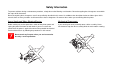
Safety Information To prevent accidents during a maintenance procedure, strictly observe the Warnings and Cautions. Do not do anything that is dangerous or not within the scope of this document. Do not do anything that is dangerous even if not specifically described in this manual. In addition to the descriptions below and those given in this manual, there are many situations and circumstances that are dangerous. Be aware of these when you are working with the printer.
Laser Beam The laser beam used for exposing process during printing is a very powerful, straight, narrow beam of light that produces extreme heat at its focal point. The laser beam is this printer is invisible. Although you cannot see the beam, it can still cause severe damage. Direct eye exposure to the laser beam may cause eye injury or blindness. Never place a mirror or a reflective tool or object in the laser beam path.
PREFACE This manual describes basic functions, theory of electrical and mechanical operations, maintenance and repair procedures of EPSON EPL-N2700. The instructions and procedures included herein are intended for the experienced repair technicians, and attention should be given to the precautions on the preceding page. The chapters are organized as follows: CHAPTER 1. PRODUCT DESCRIPTIONS Provides a general overview and specifications of the product. CHAPTER 2.
Revision Status Revision Issued Date 0 January 26, 1999 Description Preliminary version
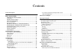
Contents Product Description OVERVIEW ................................................................................................. 12 BASIC SPECIFICATIONS .......................................................................... 13 CONTROLLER SPECIFICATIONS ........................................................ 13 Configuration .......................................................................................... 14 ENGINE SPECIFICATIONS ..........................................................
Troubleshooting Overview ..................................................................................................... 80 Printer Messages ................................................................................... 80 Message List ...................................................................................... 80 Message Descriptions ........................................................................ 82 Service-call Error ...........................................................
Overview ................................................................................................... 136 Maintenance by Users .......................................................................... 136 Replacement of Consumable Items ..................................................... 136 Maintenance by Servicers .................................................................... 137 Appendix Connector Summary ...............................................................................
PRODUCT DESCRIPTION
EPL-N2700 Revision A 1.1 Overview The EPL-N2700 is a business-oriented page printer making the most use of the laser diode and the electrical photo technology. The main feature of the printer are as follows: IEEE l284 based parallel interface (supports ECP) RS-232C serial interface Ethernet Interface (100/10Base-TX) ENGINE FEATURES SOFTWARE High-speed, highly reliable A3 Engine (Maximum duty cycle is 100,000 sheets per month).
EPL-N2700 Revision A 1.2 Basic Specifications This section describes the basic specifications of the EPL-N2700. 1.2.1 Controller Specifications CPU VR4310 / 166MHz RAM Figure 1-1. Exterior View of the EPL-N2700 Standard 16MB (on-board)*1 Optional 8MB*2/16MB*2/32MB/64MB/128MB/ 256MB*3 (SDRAM type,1 slot) Can be expanded up to 256MB.
EPL-N2700 Revision A 1.2.2 Configuration INTERFACES Standard interface: Parallel interface: Bidirectional parallel I/F (B type connector) (IEEE-1284 compliant / Compatibility, Nibble and ECP mode) Table 1-1. Configuration Classification Serial interface: RS-232C Ethernet 100/10BaseTX Optional interface: The following configuration set on the controller varies according to the destination. (See Table 1-1.) Settings are made in factory using the jumper resistance.
EPL-N2700 Revision A 1.2.3 Engine Specifications FIRST PRINT PRINTING METHOD Table 1-3. First Print Semiconductor laser beam scan + dry-powdered single-component magnetic toner electro-photographic printing Single Print Duplex Print Paper Size RESOLUTION 600DPI PRINTING SPEED MP Cassette Cassette 1 MP Cassette Cassette 1 A4 (LEF*) 11.2 11.2 20.1 20.1 A3 (SEF**) 13.3 13.3 22.4 22.4 A5 (LEF) 10.9 − 17.7 − LTR (LEF) 11.3 11.3 20.3 20.
EPL-N2700 Revision A See Table 1-4 for paper source specifications. Table 1-4. Paper Supply / Paper Size / Capacity Paper Source / Capacity 250 sheets Standard MP Tray Option • Standard size paper within the size of: A5(LEF*1) - A3(LEF*2) Half Letter - Ledger(SEF) (8.5" x 5.
EPL-N2700 Revision A 1.2.4 Paper Specifications See Table 1-5 for the paper sources and their paper availability. Table 1-5.
EPL-N2700 Revision A CONSUMABLES AND OPTIONS With a 5-bin Unit installed: Imaging Cartridge Table 1-6. Paper Ejection Capacity with 5-bin Unit Bin 1 Paper Type SUPPORTED PAPER SIZES MP Cassette: Normal paper (60 - 90 g / m2) Width =86 to 297 mm (3.39 to 11.7 ") Shifting 250 sheets 250 sheets Envelopes, OHP sheets 10 sheets Thick paper (TBD) (90 - 163 g / m2) Cassette 1: Bin 2 - 4 Normal 100 sheets − − Width = 215.9 to 297 mm (3.9 to 11.
EPL-N2700 Revision A POWER CONSUMPTION Printer Main Body: See Table 1-8. Table 1-8. Power Supply Specification Item Input Voltage Rated Frequency 100V Model 200V Model 120V ±10% (90 to 132V) 220 - 240V ±10% (198 to 264V) 50 - 60Hz ±3Hz 50 - 60Hz ±3Hz 11.5 A 6.0 A Rated Current Power Consumption • • • • Maximum: Continuous printing: Stand-by (Heater ON): Stand-by (Heater OFF): DC24 V and DC5 V are supplied from the printer. Average consumption current: 1.
EPL-N2700 Revision A 1.2.
EPL-N2700 Revision A PAPER PATH AVAILABILITY PRINTABLE AREA Table 1-9. Paper Path Availability Standard paper Normal paper OHP sheet Postcard Label Thick paper Envelope Special Paper MP Cassette RF R P P P P P Cassette 1 RF R N N N N N 500-sheet lower cassette unit RF R N N N N N Large Capacity Lower Cassette RF R N N N N N Duplex Unit RF R N N N N N RF: R: P: N: Printable area: TBD Guaranteed print area:Area other than 4 mm inward from each edge.
EPL-N2700 Revision A 1.2.7 Reliability, Durability, And Maintainability MPBF PRINT POSITION ACCURACY 60,000 sheets (For single-side print) NOTE: MPBF is an average number of sheets printed between failures, where "failure" indicates a condition that requires part replacement or that cannot be corrected by user.
EPL-N2700 Revision A Table 1-12. Paper Skew Print mode Direction A4 (LEF) A3 (SEF) Single-side print Main scan direction (c − d) Sub scan direction (a − b) ±2.mm TBD TBD ±1.5.mm TBD Duplex print Main scan direction (c − d) Sub scan direction (a − b) ±3.mm TBD TBD ±2.5.mm TBD Ambient Illumination: 3000 lux or less (Must avoid direct sunlight.) Space Requirement: To ensure proper operation of the printer, sufficient open space must be left around printer, as indicated in Figure 1-3.
EPL-N2700 Revision A 1.2.8 Environmental Condition For Storage And Transportation (Including Consumable Items) TEMPERATURE AND HUMIDITY VIBRATION TOLERANCE Table 1-13.
EPL-N2700 Revision A 1.2.9 Electrical Specifications DIELECTRIC STRENGTH AC LINE NOISE Insulation shall not break down when the following voltage is applied between primary circuit and chassis for 1 minute: Pulse width: 50 to 1000 ns Pulse polarity: +/- Repetition: Asynchronous Modes: Common / Normal LEAKAGE CURRENT Voltage: 1KV (Parts must be able to withstand 2KV without damage) 3.
EPL-N2700 Revision A 1.2.10 Safety Approval POWER CONSUMPTION SAFETY REGULATION In compliance with International Energy Star program Table 1-14. Safety Regulation Model OTHERS Applicable Standard 100V version • UL 1950 • CSA 22.2 No.950 200V version • TUV-GS (EN60950) • CCIB • Complies with a safety regulation of the following countries: Russia, Singapore, Hong Kong (IEC950), Korea SAFETY REGULATION (LASER RADIATION) Table 1-15.
EPL-N2700 Revision A 1.2.11 Consumable Item ENVIRONMENTAL CONDITION FOR STORAGE AND TRANSPORTATION This printer's only consumable part is the Imaging Cartridge. Table 1-18. Environmental Conditions - Consumables SPECIFICATIONS Name ET Cartridge Components • • • • OPC Drum Charging unit Development unit Single-component unmagnetic black toner Life Average: 15,000 pages *1 *2 Weight Approximately 2.
EPL-N2700 Revision A 1.3 External Interface Specifications 1.3.1 Host Interface Usage Configurations The EPL-N2700 supports the following interfaces. The EPL-N2700 has the automatic interface switching mode. however, the interface to be used can be fixed by a control panel operation. Bidirectional parallel I/F (standard) Table 1-19. Host Interface Usage Configurations RS-232C serial (standard) Parallel I/F Serial I/F Ethernet I/F Type B I/F 1.
EPL-N2700 Revision A 1.3.2 Parallel Interface Interface type: IEEE1284 bidirectional high-speed parallel interface Operation modes: Compatibility, Nibble, ECP Connector: 57RE-40360-830B(D7A) DDK or equivalent Applicable plug: Amphenole equivalent Device ID: *1; MFG: CMD: MDL: CLS: DES: EPSON; PJL, EJL, ESCPL2-00, ESCP9-84, PRPXL24-01, HP ENHANCED PCL5, HPGL2-01, ESCPAGE-04, ESCPAGE-04∗∗ *2; *3 PRINTER; EPSON EPL-N2700; 1.3.
EPL-N2700 Revision A 1.3.4 Ethernet I/F I/F type: 10BaseT, 100BaseT, Half Duplex, Full Duplex (Switched at power on) Pin Signal Name I/O 1 Tx+ O 2 Tx- O IPX/SPX (IPX, SPX, NCP, RIP, SAP, PrintServer, RemotePrinter, NDS, SNMP) 3 Rx+ I 4 N.C. − NetBIOS (SMB) NetBEUI 5 N.C. − 6 Rx- I TCP/IP (IP, UDP, TCP, LPR, FTP, TELNET, APR, ICMP, RARP, BOOTP, DHCP, SNMP, HTTP) 7 N.C. − 8 N.C. − Communication protocol: Table 1-20.
EPL-N2700 Revision A 1.3.5 Type-B I/F Table 1-21. Emulations Available This printer is equipped with one slot for an optional Type-B interface card. Emulation Emulation Type Entity Type LJ4 PCL5E-00 EPSONPCL5 MTP600dpi,PW7016dt600dpi,PRG(∗∗∗∗)rev, AP1300ma,SPD0fast (∗∗∗∗: ROM version) GL/2 HPGL2-01 EPSONHPGL2 PS POSTSCRIPT-00 LaserWriter FX ESCP9-84 EPSONFX Printer Name: Factory value is the same as the Product Name.
EPL-N2700 Revision A 1.4 Panel Operation The control panel of the EPL-N2700 includes a variety of buttons and indicator lamps, together with an LCD. The user can use the panel to select the printer's operating mode, to set the various printer functions, and to view settings and status information. 1.4.1 Control Panel.
EPL-N2700 Revision A Form Feed button If the printer contains data but is not enabled for printing (if Form Feed lamp is on), this switch causes printer to output printing results and eject the paper. (This button does not cause ejection if Form Feed lamp is off.) Continue button Clears error (if pressed while Continue LED is blinking). When printer is in On-Line state, this button will also clear any warning display that may appear on the LCD.
EPL-N2700 Revision A 1.4.2 Panel Settings Table 1-23. SelecType Option (2/7) 1.4.2.1 Setting Items MENU Button ITEM Button The following tables show the panel setting options available. Printing Menu Table 1-22.
EPL-N2700 Revision A Table 1-25. SelecType Option (4/7) Table 1-24. SelecType Option (3/7) MENU Button MENU Button ITEM Button ITEM Button VALUE Button Setup Menu Interface Time Out Standby *14 Lang Panel Lock *15 Toner *13 Multibin *27 Finisher *12 Page Count *13 SelecType Init Auto / Parallel / Serial / Network / AUX *2 0, 5 - 60 - 300 (step: 1) Enable / Disable English / Français / Deutsch / ITALIANO / ESPANOL / SVENSKA / Dansk / Nerderl.
EPL-N2700 Revision A Table 1-26. SelecType Option (5/7) Table 1-27. SelecType Option (6/7) MENU Button MENU Button ITEM Button VALUE Button ITEM Button GL2 Menu GL-Mode Scale Origin Pen End Join Pen0/1 Pen2 *16 - 6 *16 GLlike / LJ4GL OFF / A0 / A1 / A2 / A3 Corner / Center Pen0 / 1 / 2 *16 - 6 *16 Butt / Square / Triangular / Round Mitered / Miteredveveled / Triangular / Round / Beveled / None 0.05 - 0.35 - 5.00 (step:0.05mm) 0.05 - 0.35 - 5.00 (step:0.
EPL-N2700 Revision A Table 1-28. SelecType Option (7/7) MENU Button ITEM Button VALUE Button Maintenance Menu *24 Engine Status Sheet Fuser Counter Clear MP Counter Clear LC1 Counter Clear LC2 Counter Clear *21 LC3 Counter Clear *21 TR Counter Clear Errlr Long Clear NOTES: 1: Appears only when an optional PostScript Level 3 DIMM is installed. 2: Appears only when an optional TypeB Interface Card is installed. 3: Appears and can be selected only when an optional lower cassette unit is installed.
EPL-N2700 Revision A 1.4.2.2 User Setting Items which are not include in the Setting Menu 1.4.2.3 Setting Item Description The items shown below are not included in the setting menu but can be set by users. The values set by the users are not cleared by the initialization through the control panel.
EPL-N2700 Revision A Table 1-30. “Multibin” Settings and Corresponding Outbins Available LC1 to LC3 Type These are basically same as the MP Type but because special paper cannot be fed from the LC1 - LC3, “Letterhead”, “Bond”, “Transprnc”, and “Labels” can not be selected. Mailbox Table 1-29.
EPL-N2700 Revision A The printer searches some consecutive empty bins in the order of Bin 2, Bin 3 - - -, and paper will be output to the empty bin which found last in the search. When “Multibin = Sorter” and “Outbin = Sorter” are selected: Duplex (Printing Menu) The sequence of ejected paper destination is Bin10 > Bin 9 > - Bin1. When “Multibin = MultiSort” and “Outbin = Sorter” are selected: If requested copies is 9 or less, ejection starts at Bin 2.
EPL-N2700 Revision A 1.4.3 One-Touch Setting 1.4.4 Special Functions The One-Touch setting function of the printer offers the quick access to the following panel setting items, which are frequently changed: Built-in special function can be selected by turning on the printer while holding down the specific combination of button(s). Table 1-32 lists the special functions supported by the printer. Table 1-31.
EPL-N2700 Revision A Hex-Dump Mode C A U T IO N Converts received data into hexadecimal ASCII codes. Effective all interfaces. Button to press: “Form Feed” while turning on the printer Exit: Switch the printer off or perform Warm-boot by job cancel or reset. This function initializes all user-selectable settings.
EPL-N2700 Button to press: Revision A Press “On Line“, “ALT“, and “Enter“ while turning on the printer. Then, when the LCD indicates “DIMM COPY MODE”, press the “Enter” button, and the printer erases the contents of the Flash ROM and then starts copying. To return to the normal status, the printer performs a warm-boot operation. 1.4.5 Maintenance Mode C A U T IO N When executing any function but “Error Log Clear”, make sure the engine is not live completely.
EPL-N2700 A servicer performs this operation once whenever the feed roller in the LC1/LC2/LC3 has been replaced. A sample print of the Engine Status Sheet is shown below: Engine Status Sheet This function returns the value for the LC1/LC2/LC3 Counter to zero and the counter value for the LC1/LC2/LC3 FR Change increases by one which are shown on the engine status sheet.
EPL-N2700 Total Counts Shows the same value as the one for the “Page Count” in the “Setup Menu”. Input: Jam counts: Shows the number of times jams occurred. ET Cartridge: Revision A Toner: Shows the remaining toner level in one percent units. OPC Drum: Shows a total time of drum’s rotation in one minute units. Cartridge Change: Shows the number of times the ET cartridge has been replaced.
EPL-N2700 Adjust Revision A LC1 Shows the adjusting value for the LC1’s main scanning direction. Set by EJL. Error Log: Shows the record of the most recent 20 errors that occurred. It includes corresponding LCD message, EJL status command, and total sheet number. They are shown in the order of recentness. The error types included are as follows: LC2 Shows the adjusting value for the LC2’s main scanning direction. Set by EJL.
EPL-N2700 Revision A 1.4.5.2 List of Data Controlled by the Engine Status Sheet and Controlling Method Table 1-33.
EPL-N2700 Revision A 1.5 Dimensions and Weight T o p V ie w DIMENSIONS Unit itself: 535 mm (W) x 545 mm (D) x 284 mm (H) With the main unit:535 mm (W) x 559 mm (D) x 712 mm (H) 500-sheet Lower Cassette Unit: 535 mm (W) x 544 mm (D) x 127.5 mm (H) (When stacked, each unit is 105 mm in height.
EPL-N2700 Revision A WEIGHT Printer main body: 30 Kg (Without any consumable or optional items) Large Capacity Lower Cassette: 17 Kg or less 500-sheet Lower Cassette Unit: 7 Kg or less (TBD) Duplex Unit: 2 Kg or less 10-bin Unit: 10-bin portion: 25.9 Kg (including packed items) Horizontal transport portion: 3.6 Kg (including packed items) 5-bin Unit: 12.
OPERATING PRINCIPLES
EPL-N2700 Revision A 2.1 Printer Mechanism Operating Principles The following diagram shows the major parts, including the sensors, and the paper paths in the printer. The printer consists of the paper feed section, print head unit (exposure section), imaging cartridge (charging section and development section), transfer section, fusing section, and paper exit section Figure 2-1.
EPL-N2700 Revision A 2.1.1 General Description of Each Section Paper Feed Section Paper is fed from either the MP Tray or Cassette 1 (universal cassette). When the printer receives a print command, the paper take-up solenoid turns ON and a sheet of paper is fed by the paper take-up roller. The timing roller front sensor (PC2) detects the fed paper and the paper is fed to the timing roller for printing.
EPL-N2700 Revision A 2.1.2 Gear/Roller Location The gears and roller in the printer are located as shows in the figurer below. The transportation motor (M2) drives the transportation system and the I/D drive motor (M1) drives the gears in the Imaging Cartridge. Transportation Motor (M2) I/C Drive Motor (M1) Figure 2-2.
EPL-N2700 Revision A 2.1.3 Electrical Component Layout The electrical component layout is as shown below. Figure 2-3.
EPL-N2700 Revision A 2.1.3.1 Switches and Sensors Location Name Table 2-1. Switches and Sensors Location Name Function TS1 Fuser Thermostat Cuts off the voltage for the heater lamp when the upper fusing roller heats up abnormally. TF1 Fuser Temperature Fuse The fuse is blown when the temperature of the upper fusing roller has risen abnormally. PC22 Cassette 1 Paper Empty Sensor Detects the paper empty condition for the Cassette 1. Signal is LOW when no paper is in the cassette.
EPL-N2700 Revision A 2.1.4 Paper Feeding Section 2.1.4.1 MP Tray Paper feeding from MP Tray The power is transmitted from the transport motor (M2) as follows to take up paper from the MP. 1) The transport motor (M2) turns counterclockwise → 2)The idle gear turns clockwise. →The MP Cassette paper take-up solenoid (SL1) turns ON. → 3) The paper take-up roller turns counterclockwise. → Paper is taken up. NOTE: Note: The rotational direction is the one viewing from the front of the printer.
EPL-N2700 Revision A MP Cassette Set Sensor (PC6) This sensor detects the installation of the MP cassette. This sensor uses a photointerrupter. When the signal is input to the CPU in the control circuit, the CPU detects that the MP Cassette has been installed. If the MP cassette is not installed in the MP Tray: The projection of the paper cassette comes off the sensor which is mounted on the printer.
EPL-N2700 Revision A (3) MP Cassette Paper Near Empty Sensor (PC5) This sensor detects the paper near empty status of the MP Cassette paper. The sensor uses a photointerrupter. As the sheets of paper in the paper cassette decrease, the paper lifting plate in the paper cassette lifts. When the paper lifting plate lifts exceeding a certain point, the MP Cassette paper near empty occurs.
EPL-N2700 Revision A MP Cassette Size Sensor The paper size for the MP cassette is detected by the rear paper guide. The paper size detection mechanism consists of the arm that joins with the rear paper guide and four mechanical switches in the printer body. When the rear paper guide is aligned with the paper size, the arm swivel accordingly, as shown below. The arm has a notch, which moves as the arm swivels to turn on/off the four mechanical switches.
EPL-N2700 Revision A NOTE: The rotational direction is the one m from the front of the printer. 2.1.4.2 Cassette 1 Paper Feeding from Cassette 1 The power is transmitted from the transport motor (M2) as described on the right to take up paper from the Cassette 1. 1)The transport motor (M2) turns counterclockwise →2)The idle gear turns clockwise. → 3) The MP Cassette paper take-up gear turns counterclockwise. →4) The MP Cassette idle gear turns clockwise. The transport clutch (CL1) turns ON.
EPL-N2700 Revision A [Separators] Double feed of paper in the Cassette 1 is prevented by the separators of the paper cassette. Cassette 1 Paper Empty Sensor (PC22) Cassette 1 Paper Near Empty Sensor (PC25) Cassette 1 Set Switch (SW3) Paper Take-up Roller Cassette 1 Right Door Detecting Sensor (PC23) Cassette 1 Paper Take-up Solenoid (SL21) Figure 2-12.
EPL-N2700 Revision A Cassette 1 Paper Size Sensor A mechanical switch is installed to the Cassette 1 to set the size of the paper set. Unlike for the MP Cassette (MP Tray), the printer detects the paper size set in the Cassette 1 (all universal cassettes) by the paper size setting dial. Each notch on the setting dial corresponds to different paper size.
EPL-N2700 Revision A Cassette 1 Paper Empty Sensor (PC22) This sensor detects the paper empty status of the Cassette 1. The sensor uses a photointerrupter. When paper runs out in the Cassette 1, paper empty occurs. When paper is present in the paper cassette: The sensor arm is pressed by the paper and it is lifted. So, the projection of the sensor arm engages with the photointerrupter. As a result, the output of the photointerrupter is “H”.
EPL-N2700 Revision A Cassette 1 Right Door Detecting Sensor (PC23) This sensor detects whether the Cassette 1 right door is closed or not. The sensor uses a photointerrupter. The right door is normally closed except when removing jammed paper. When the right door is closed: The projection of the side door engages with the photointerrupter of the Cassette 1. Thus, the output of the photointerrupter is “H”.
EPL-N2700 Revision A 2.1.4.3 Paper Feed The paper taken up by the paper take-up section is fed to the transfer section after registration compensation. Registration Compensation To eliminate any paper slant (skew), registration compensation is made by controlling the rotating timing of the paper take-up roller and timing roller. The taken up paper passes the timing roller sensor (PC2) and reaches the timing roller. At this moment, the printer delays turning timing of the timing roller for a moment.
EPL-N2700 Revision A 2.1.5 Printhead Unit (Exposure Section) The print head unit incorporates a laser diode that emits the laser beam corresponding to the print image data. The spot of the laser beam emitted from the laser diode is shaped in a circle through the collimator lens. Then, it is applied to the heptagonal polygon mirror via the cylindrical lens. The polygon mirror is turned by the polygon motor in the print head unit in the direction as shown by the arrow.
EPL-N2700 Revision A 2.1.5.1 Print Process Sequence The print process sequence is as shown in the following figure. For details, See Section 2.1.5.1 Figure 2-20.
EPL-N2700 Revision A 2.1.6 Imaging Cartridge 2.1.6.1 Part Names and Functions of the Imaging Cartridge The following illustrates the construction of the imaging cartridge. The power to the gears of the imaging cartridge is transmitted from the I/C drive motor (M1) of the printer main body. The I/C drive motor (M1) turns clockwise viewing from the front of the printer. Sleeve Roller: Feeds toner to the electrostatic latent image formed on the surface of the PC drum to produce a visible toner image.
EPL-N2700 Revision A 2.1.6.2 Charging Section 2.1.6.3 Development Section Before producing an electrostatic latent image on the surface of the PC drum with a laser beam, the PC drum is charged by static electricity with the rotating charge bush so that the surface of the PC drum is negatively charged. The charging system uses the rotating charge brush system. Since this charging system can apply charge directly to the PC drum, charging is possible at a low voltage, producing negligible amount of ozone.
EPL-N2700 Revision A The following illustrates an example where the letter “A” is written by the laser beam and toner sticks onto the letter “A” on the surface of the PC drum. Sleeve Roller PC Drum Operation of the Toner Empty Sensor: The toner empty sensor detects the toner-empty status. The sensor is a photo reflector mounted on the printer. If low toner condition occurs, the light emitted from the LED of the photo reflector passes the window of the toner hopper and reflected by the mirror.
EPL-N2700 Revision A 2.1.6.4 Transfer Section The transfer roller transfers the toner image on the surface of the PC drum onto the paper. A positive transfer bias is applied to the transfer roller so that the toner (reduced negative voltage) on the surface of the PC drum sticks to the paper. The transfer bias is transmitted via; HV transformer (high voltage unit) → contact plate → compression spring → transfer roller bushing → transfer roller.
EPL-N2700 Revision A 2.1.6.5 Fusing Section The power from the transport motor (M2) is transmitted to the upper fusing roller so that the toner-transferred paper is fed from the transfer section to the fusing section. The paper is heated to melt the toner by the upper fusing roller and pressed by the upper and lower fusing rollers. The upper fusing roller is heated by the fusing roller heater lamp (H1) which is built in it.
EPL-N2700 Revision A NOTE:190°C --> 183°C for overseas versions (TBD) Rush current preventing circuit for heater lamp To prevent rush current when an AC voltage is applied to the heater lamp, the CPU turns off the Remote 1 signal and turns on the Remote 2 signal in the form of pulse. By outputting Remote 2, the additional resistor is connected in series to the heater lamp to suppress the rush current flowing into the heater lamp.
EPL-N2700 Revision A 2.1.6.6 Paper Exit Section The paper fed from the fusing section passes through the paper exit roller and ejected to the output tray. The transmit power for feeding paper is given by the transport motor (M2) and transmitted in the order from 1) ~ 12) shown in the figure. When the duplex unit is installed, however, drive from the fusing section is mechanically cut off, and the duplex unit is driven by the internal motor of the unit.
EPL-N2700 Revision A 2.1.7 Detection whether New or Used Imaging Cartridge The printer has the function to detect whether the newly installed imaging cartridge is a new one or used one. This function is equipped because the PC drum counter has to be reset when the imaging cartridge is replace with a new one. As shown in the figure below, a fuse is connected in parallel with a resistor. In a new imaging cartridge, the fuse is not blown.
EPL-N2700 Revision A 2.2 Electrical Circuit Operating Principles. 2.2.1 System Layout 2.2.1.1 Drive Section The figure below shows the drive mechanism that consists of the motors, solenoids, clutch, rollers, and sensors Figure 2-33. System Layout - Drive Section Operating Principles Electrical Circuit Operating Principles.
EPL-N2700 Revision A 2.2.1.2 Electrical Section The power supply system and the signal lines are shown below. The power supply unit supplies DC +5 V and DC +24 V to the main control board. It also supply an AC voltage to the heater lamp. The main controller (video controller) receives a compressed print data from the host PC through an interface. The main circuit generates image data. The image data is sent to the print head unit via the engine control board.
EPL-N2700 Revision A 2.2.2 Main Circuit (Video Controller) 2.2.2.1 Main Component in the Main Circuit Board Data sent from the host PC is input to the main circuit via an interface or network board. The C269MAIN, the main circuit of the printer, converts data from the PC into raster data to generate video signals. The video signals turn on/off the laser diode on the printhead to form latent images on the PC drum. The following table lists the main components on the main circuit board. Table 2-3.
TROUBLESHOOTING
EPL-N2700 Revision A 3.1 Overview 3.1.1.1 Message List Since the mechanism of page printer is complicated, it is difficult to isolate the cause of the problem exhibited. This chapter explains how to isolate the cause of the problems as well as remedies based on the abnormal phenomenons and error conditions. See the following table which lists the messages indicated by the printer. Table 3-1. Printer Message Message Type 3.1.1 Printer Messages (Displays at power on) Service Req.
EPL-N2700 Revision A Table 3-1. Printer Message Message Cover C3 Open Table 3-1.
EPL-N2700 Revision A 3.1.1.2 Message Descriptions After removing paper from the FD, press the Continue button, and the printer resumes printing. This section describes the messages specific to EPL-N2700. x Error yyy (error) Given when a problem occurs with the paper feeders or output bins. Power down temporarily, check the connection on the device where the error has occurred and start-up again. The printer attempts to eject paper to the multibin , but the bin is full.
EPL-N2700 Revision A none of the paper source has paper in it, the message “Manual Feed ssss ttt” is indicated again. Even though the fed paper size does not match ttt, “Check Paper Size” is not indicated. The output device used is other than selected one because the selected device is restricted. Remove Output Paper (error) When the multibin mode is changed from the previous one, paper remains in the multibin unit.
EPL-N2700 Revision A 3.1.2.2 Controller Related Error List The following table lists the controller related errors which can occur in this printer. Table 3-3.
EPL-N2700 Revision A 3.1.2.3 Clearing the Service-call Error 3.1.4 Troubleshooting Service-call error can be cleared by taking appropriate actions as shown in Chapter 1 / Section 1.4.4 “Special Functions”. Troubleshooting for the engine related problems are described in the following sections. 3.1.3 Adding on RAM 3.1.4.1 The Printer will not Start Table 3-4. Troubleshooting - The Printer will not Start.
EPL-N2700 Revision A 3.1.4.2 The Printer will no Print. 3.1.4.3 Image Quality Problems Table 3-5. Troubleshooting - The Printer will not Print. Symptom Analysis Is the On Line LED ON? The printer does not eject paper. The printer ejects blank sheets of paper. You get a message other than “Ready.” Finding No Table 3-6. Troubleshooting - Image Quality Problem Action Symptom Press the On Line button to turn ON the On Line LED. Yes Follow the message.
DISASSEMBLY/ASSEMBLY
EPSON EPL-N2700 4.1 Overview Rev. A 4.1.2 Tools The tools used to disassemble/assemble this printer are as listed below: 4.1.1 Precaution Observe the following instruction well before starting servicing. W A R N IN G C A U T IO N Before servicing, turn the printer power off and unplug the power code from the AC socket. Before removing the fuser and nearby parts, turn the printer off and wait for at least 30 minutes to lower the fuser temperature.
EPSON EPL-N2700 Rev. A 4.1.3 Small Parts The small parts used in the printer are listed in the following table. Reference No. Size Name 2101 3×6 Bind screw 2703 4×6 3104 3×8 3114 4×6 3211 3 × 14 Tapping screw (Flat head B-tite screw) 3305 3×8 Tapping screw (Pan head B-tite screw) 3402 3×6 3435 3 × 30 Tapping screw (Pan head S-tite screw) 3501 3×6 3504 3×8 3 × 10 Appearance Table 4-2. Small Part Classification Reference No.
EPSON EPL-N2700 Reference No. Size Name Tapping screw (Binding head B-tite screw) 3907 3×8 3923 3 × 10 4011 3×8 4012 3×6 4021 3×8 4025 3×6 7107 4×6 8501 Appearance Tapping screw (Binding head S-tite screw) Setscrew Plane washer 9102 #2 9103 #2 9105 #3 9107 #4 9111 #5 9112 #6 9140 #5 9151 #7 9301 Rev.
EPSON EPL-N2700 Rev. A 4.2 Disassembly Procedure This section contains the disassembly procedure for EPL-N2700. The flowchart for the disassembly procedure is as shown below. For the information on the parts which are not included in this Chapter, refer to Chapter 7 / Exploded Diagrams. Figure 4-2. Disassembly Flowchart (2) Figure 4-1.
EPSON EPL-N2700 Rev. A 4.2.1 ROM DIMM Removal 1. Release two hooks fixing the access cover to the Upper Case and remove the access cover. 2. Remove two screws (1305) securing the upper shield cover and remove the upper shield cover. 3. Remove ROM DIMM from the PROG DIMM socket. Access Cover Upper Case Upper Shield Cover Shield Cover Figure 4-3.
EPSON EPL-N2700 Rev. A 4.2.2 Paper Eject Sensor Removal 1. Open the Fuser Unit Cover and release two hooks securing the Paper Eject Sensor Cover to the Fuser Unit and remove the cover. Paper Eject Sensor Cover Sensor Harness Paper Eject Sensor Hooks Sensor Stopper Fuser Unit PC3 Actuator Torsion Spring Figure 4-5. Paper Eject Sensor Removal Fuser Unit Cover Figure 4-4. Paper Eject Sensor Cover Removal 2. Remove the sensor stopper from the Fuser Unit. 3.
EPSON EPL-N2700 4.2.3 MP Cassette Paper Take-up Roller Removal Rev. A 4. Remove the C-clip and remove the Paper Take-up Roller. 1. Take out the MP Cassette from the printer body. Figure 4-6. Taking out the MP Cassette Figure 4-8. MP Cassette Paper Take-up Roller Removal 2. Remove the C-clip from the Paper Take-up Roller. 3. Slide the Paper Take-up Roller Assembly to the rear and remove the Paper Take-up Roller Assembly from the bushing (front). Figure 4-7.
EPSON EPL-N2700 Rev. A 4.2.4 Transfer Section C A U T IO N 4.2.4.1 Transfer Roller Removal 1. Open the vertical transport door. Never touch the transfer roller surface with your bare hands. Doing so may affect print quality. If you have replaced the Transfer Roller Unit, be sure to perform “TR Counter Clear” in the maintenance mode. (See Chapter 1 / Section 1.4.5.) Figure 4-9. Opening the Vertical Transport Door 2. Put up the transfer front guide plate. 3. Remove the Transfer Roller. Figure 4-10.
EPSON EPL-N2700 Rev. A 4.2.4.2 Transfer Unit Removal 4.2.4.3 Timing Roller Front Sensor Removal 1. Release two hooks securing the Transfer Unit to the vertical transport door and lift the Transfer Unit a little. 1. Remove the Transfer Unit. (See Section 4.2.4.2.) 2. Disconnect the harnesses for the Timing Clutch and Timing Roller Front Sensor from the corresponding connectors. Then remove the Transfer Roller Unit from the vertical transport door. 2.
EPSON EPL-N2700 Rev. A 4.2.4.4 Timing Clutch Removal C H E C K P O IN T 1. Remove the Transfer Unit. (See Section 4.2.4.2.) 2. Remove the E-ring (9140) fixing the Timing Clutch to the Transport Roller (Timing Drive Roller) and remove the Timing Clutch from the Holder Assembly. When installing the Timing Clutch, be sure to align the fork on the clutch with the mounting point on the Holder Assembly. Figure 4-13.
EPSON EPL-N2700 Rev. A 4.2.4.5 Timing Roller Removal 5. Remove two tension springs securing the bushing for the Timing Driven Roller to the Holder Assembly. 1. Remove the Transfer Unit. (See Section 4.2.4.2.) 2. Put up the transfer front guide plate. (See Section 4.2.4.1.) 3. Remove the Timing Clutch. (See Section 4.2.4.4.) 4. Release the hook securing the Guide Bar to the Holder Assembly and remove the paper dust remove filter from the Holder Assembly. 6.
EPSON EPL-N2700 Rev. A 4.2.4.6 Internal Cooling Fan Removal 4.2.5 Separating the Printer 1. Remove the Transfer Unit. (See Section 4.2.4.2.) 1. Remove 1 screw (3727) securing the frame to the back of the Cassette 1, and remove the frame. 2. Disconnect the motor harness from the connector. 3. Remove two screws (3704) securing the Internal Cooling Fan to the vertical transport door, and remove the Internal Cooling Fan. 2.
EPSON EPL-N2700 Rev. A 4.2.6 Rear Cover Removal 4.2.7 Transport Motor Removal 1. Remove one screw (3541) securing the CN cover to the printer and remove the CN cover. 1. Remove the Rear Cover. (See Section 4.2.6.) 2. Remove the Harness Cover. 2. Remove four screws (3501) securing the Transport Motor to the printer frame and remove the Transport Motor. 3. Remove the rear optional cover. 3. Disconnect the harness for the Transport Motor from the connector. 4.
EPSON EPL-N2700 Rev. A 4.2.8 I/C Drive Motor Removal 4.2.9 MP Cassette Size Sensor Removal 1. Remove the Rear Cover. (See Section 4.2.6.) 1. Remove the Rear Cover. (See Section 4.2.6.) 2. Remove four screws (3501) securing the I/C Drive Motor to the printer frame and remove the I/C Drive Motor. 2. Remove the MP Cassette. 3. Disconnect the harness for the I/C Drive Motor from the connector. I/C Drive Motor Motor Harness 3.
EPSON EPL-N2700 Rev. A 4.2.10 Paper Size Sensor Removal 4.2.11 Top Cover Removal 1. Remove the Rear Cover. (See Section 4.2.6.) 1. Remove two screws (3541) securing the Top Cover to the printer through the left cover. 2. Remove the MP Cassette. 2. Lift up the left edge of the Top Cover and remove the Top Cover. 3. Remove one screw (3501) securing the paper size sensor bracket to the printer frame, and remove the plate along with the sensor. 4.
EPSON EPL-N2700 Rev. A 4.2.12 Toner Empty Sensor Removal 1. Remove the Top Cover. (See Section 4.2.11.) 2. Remove one screw (3504) securing the Toner Empty Sensor to the printer frame and remove the sensor. 3. Disconnect the harness from the connector on the sensor. Harness Toner Empty Sensor Figure 4-23.
EPSON EPL-N2700 Rev. A 4.2.13 Main Circuit Board Removal 1. Remove the Rear Cover. (See Section 4.2.6.) 6. Remove seven screws (1305) securing the Interface bracket to the printer frame, and remove the Interface bracket along with the Main Circuit Board by moving it upward. 2. Remove the Top Cover. (See Section 4.2.11.) 7. Remove the Contact Plate from the Interface bracket. 3. Remove the following screws and remove the Shield Cover. 8.
EPSON EPL-N2700 Rev. A 4.2.14 Engine Controller Board Removal 1. Remove the Rear Cover. (See Section 4.2.6.) 2. Remove the Top Cover. (See Section 4.2.11.) 3. Remove the following screws and remove the Shield Cover. Sixteen screws (3501: marked with A in the figure) securing the Shield Cover to the printer frame. Three screws (1305: marked with B in the figure) securing the Shield Cover to the Interface bracket. 4.
EPSON EPL-N2700 Rev. A Figure 4-26. Connector Layout 10. Remove four screws (1305) securing the Engine Controller Board to the P/H plate and remove the Engine Controller Board.
EPSON EPL-N2700 Rev. A 4.2.15 Power Supply Unit Cooling Fan Removal 1. Remove the Rear Cover. (See Section 4.2.6.) 2. Remove the Top Cover. (See Section 4.2.11.) Harness 3. Remove the following screws and remove the Shield Cover. Sixteen screws (3501: marked with A in the figure) securing the Shield Cover to the printer frame. Power Supply Unit Cooling Fan Three screws (1305: marked with B in the figure) securing the Shield Cover to the Interface bracket. 4.
EPSON EPL-N2700 Rev. A 4.2.16 High Voltage Unit Removal 1. Remove the Top Cover. (See Section 4.2.11.) 2. Open the vertical transport door. 3. Remove two screws (3504) securing the High Voltage Unit Cover to the printer frame, and remove the cover. 4. Disconnect harnesses from the connector on the High Voltage Unit. Figure 4-29. High Voltage Unit Removal Figure 4-28. Harness Removal 5. Remove two screws (3501) securing the High Voltage Unit to the printer frame.
EPSON EPL-N2700 Rev. A 4.2.17 Front Cover Removal 4.2.18 Control Panel Removal 1. Remove the Top Cover. (See Section 4.2.11.) 1. Remove the Top Cover. (See Section 4.2.11.) 2. Take out the MP Cassette. 2. Remove the Front Cover. (See Section 4.2.17.) 3. Open the vertical transport door and remove one screw (3501) securing the Front Cover to the printer frame. 3. Disconnect the control panel harness connecting to the Main Circuit Board from the CN3. (See Section 4.2.13.) 4.
EPSON EPL-N2700 Rev. A 4.2.19 Printhead Unit Removal 1. Remove the Rear Cover. (See Section 4.2.6.) 2. Remove the Top Cover. (See Section 4.2.11.) 3. Remove the Front Cover. (See Section 4.2.17.) 4. Remove the following screws and remove the Shield Cover. (See Section 4.2.13.) Sixteen screws (3501: marked with A in the figure) securing the Shield Cover to the printer frame. Three screws (1305: marked with B in the figure) securing the Shield Cover to the Interface bracket. 5.
EPSON EPL-N2700 Rev. A 12. Remove four screws (3501) securing the Left Reinforce Plate to the printer frame and PH Plate and remove the Left Reinforce Plate. 13. Remove four screws (3501) securing the PH Plate from the front and rear sides of the printer frame. 14. Remove one screw (3501) securing the ground wire from the Printhead Unit to the PH Plate, and remove the ground wire. 15. Remove four screws (3520) securing the Printhead Unit to the PH Plate and remove the Printhead Unit. Figure 4-33.
EPSON EPL-N2700 4.2.20 Power Supply Unit Removal Rev. A 8. Release the harness connecting from the Power Supply Unit to the Fuser Unit from the cable clamp attached to the Power Supply Unit. 1. Remove the Rear Cover. (See Section 4.2.6.) 2. Remove the Top Cover. (See Section 4.2.11.) 9. Remove seven screws (3501) securing the Power Supply Unit to the Power Supply Unit Mounting Plate. 3. Remove the Front Cover. (See Section 4.2.17.) 4.
EPSON EPL-N2700 Rev. A 4.2.21 Fusing Section 4.2.21.1 Fuser Unit Removal 1. Open the vertical transport door. (See Section 4.2.4.) 2. Remove the Front Cover. (See Section 4.2.17.) 3. Disconnect the heater lamp harness from the connector (heater power source) on the front and release the harness from the cable clamp and edge cover which are on the printer frame. Figure 4-37. Fuser Unit Removal C A U T IO N The Fuser Unit is hot right after printing.
EPSON EPL-N2700 4.2.21.2 Heater Lamp Replacement 1. Remove the Fuser Unit. (See Section 4.2.21.1.) Rev. A 4. Remove one screw (1305) securing the Heater Lamp Holder (front) to the Fuser Unit Frame Assembly, and remove the Heater Lamp Holder and the Heater Lamp. 2. Release the joint for the Fuser Unit Cover and the Fusing Roller Heater Lamp Front Cover. 3.
EPSON EPL-N2700 Rev. A 4.2.21.3 Fusing Roller Thermistor / Thermostat / Temperature Fuse Removal 1. Remove the Fuser Unit. (See Section 4.2.21.1.) 2. Release the joint for the Fuser Unit Cover and the Fusing Roller Heater Lamp Front Cover. 3. Remove one screw (3501) securing the Fusing Roller Heater Lamp Front Cover to the Fuser Unit Frame Assembly, and remove the Fusing Roller Heater Lamp Front Cover. (See Section 4.2.21.2.) 4.
EPSON EPL-N2700 Rev. A 9. Remove one screw (1305) securing the Heater Lamp Holder (front) to the Fuser Unit Frame Assembly and remove the Heater Lamp Holder and Heater Lamp. (See Section 4.2.21.2.) 11. Remove the shoulder screws securing the right and left levers to the front and rear frames in the Fuser Unit, and remove the levers along with the torsion spring, spacers and Front Guide Plate. 10.
EPSON EPL-N2700 13. Remove one pressure spring on the front, E-ring (9107), and remove the yellow Pressure Lever Assembly. Rev. A 16. Remove the Lower Fusing Roller by pulling it out from the gear side. Figure 4-46. Lower Fusing Roller Removal Figure 4-44. Front Pressure Lever Removal 14. Remove the Upper Fusing Roller and the bearings. 17. Remove one screw (1309) securing the Fusing Roller Thermistor to the Fuser Unit Frame Assembly and remove the Fusing Roller Thermistor. Figure 4-45.
EPSON EPL-N2700 18. Remove two screws (1305) securing the Fusing Roller Thermostat to the Fuser Unit Frame Assembly and remove the Fusing Roller Thermistor. Rev. A 4.2.21.4 Upper Paper Separator Finger Removal 1. Remove the Upper Paper Separator Finger Assembly. (See Section 4.2.21.4.) 2. Slide the fixing shaft from the Upper Paper Separator Finger Assembly and remove the Upper Paper Separator Fingers. Figure 4-48. Fuser Lamp Termistor Removal 19.
EPSON EPL-N2700 Rev. A 4.2.21.5 Lower Paper Separator Finger Removal 4.2.21.6 Upper Paper Eject Roller Removal 1. Remove the Lower Fusing Roller. (See Section 4.2.21.3.) 1. Remove the Fuser Unit. (See Section 4.2.21.1.) 2. Remove the tension spring fixing the Lower Paper Separator Finger to the Fuser Unit Frame. 2. Release the joint for the Fuser Unit Cover and the Fusing Roller Heater Lamp Front Cover. 3.
EPSON EPL-N2700 Rev. A 4.2.21.7 Lower Paper Eject Roller Removal 1. Remove the Fuser Unit. (See Section 4.2.21.1.) 2. Remove the Upper Paper Eject Roller. (See Section 4.2.21.6.) 3. Remove one E-ring (9102) securing the Lower Paper Eject Roller to the Fuser Unit Frame Assembly and two torsion springs, and remove the Lower Paper Eject Roller. Figure 4-53.
EPSON EPL-N2700 4.2.22 Drive Unit Removal 1. Separate the printer. (See Section 4.2.6.) 2. Remove the Rear Cover. (See Section 4.2.6.) 3. Remove the Top Cover. (See Section 4.2.11.) 4. Remove the Front Cover. (See Section 4.2.17.) 5. Remove the Transport Motor. (See Section 4.2.7.) Rev. A 8. Disconnect the fusing roller thermistor harness and the paper eject sensor harness which are connecting to the Fuser Unit Reinforce Plate from the relay connectors. 9.
EPSON EPL-N2700 11. Remove one retaining ring (9302) fixing the bushing to the bracket for the Gear (49T) and remove the bushing. 12. Release the harness from the clamp attached to the bracket for the Gear (49T). 13. Remove the harness for the MP Cassette Paper Take-up Solenoid (SL1). Rev. A 15. Inserting a hand from the bottom of the printer, remove one C-clip attached to the Transport Transmission Gear, and remove the Transport Transmission Gear and the bushing from the Driver Unit. 16.
EPSON EPL-N2700 4.2.22.1 MP Cassette Paper Take-up Solenoid (SL1) Removal Rev. A 4.2.22.3 MP Cassette Paper Empty Sensor Removal 1. Separate the printer. (See Section 4.2.6.) 1. Separate the printer. (See Section 4.2.6.) 2. Remove the Drive Unit. (See Section 4.2.22.) 3. Remove one screw (3704) securing the solenoid and the solenoid cover to the Drive Unit, and remove the solenoid cover. 2.
EPSON EPL-N2700 Rev. A 4.2.22.4 MP Cassette Paper Near Empty Sensor Removal 1. Separate the printer. (See Section 4.2.6.) 2. Remove one screw (3501) securing the bracket for the MP Cassette Paper Near Empty Sensor and remove the MP Cassette Paper Near Empty Sensor along with the bracket. 3. Remove the cover from the bracket. 4. Remove the harness from the connector on the sensor. Figure 4-60.
EPSON EPL-N2700 Rev. A 4.2.23 Cassette 1 Disassembly 4.2.23.1 Paper Take-up Roller Removal 1. Separate the printer. (See Section 4.2.6.) C A U T IO N If you have replaced the Paper Take-up Roller, be sure to perform “LC1 Counter Clear” in the maintenance mode. (See Chapter 1 / Section 1.4.5.) 2. Unlock the Paper Take-up Roller. Then slide the Paper Take-up Roller along the shaft plate and remove it. Figure 4-61.
EPSON EPL-N2700 Rev. A 4.2.23.2 Cassette 1 Paper Empty Sensor Removal 4.2.23.3 Cassette 1 Paper Near Empty Sensor Removal 1. Take out the Cassette 1. 1. Take out the Cassette 1. 2. Separate the printer. (See Section 4.2.6.) 2. Separate the printer. (See Section 4.2.6.) 3. Release three hooks attaching the holder to the Guide Plate and remove the holder. 3. Release three hooks attaching the holder to the Guide Plate and remove the holder. 4.
EPSON EPL-N2700 Rev. A 4.2.23.4 Paper Size (Paper Size Switch) Sensor Removal 4.2.23.5 Cassette 1 Control Board (PWB-A) Removal 1. Take out the Cassette 1. 1. Take out the Cassette 1. 2. Separate the printer. (See Section 4.2.6.) 2. Separate the printer. (See Section 4.2.6.) 3. Remove three screw (3704) securing the bracket for the Paper Size Sensor to the frame in the Cassette 1 and remove the Paper Size Sensor along with the bracket. 3.
EPSON EPL-N2700 Rev. A 4.2.23.6 Cassette 1 Paper Take-up Solenoid Removal 1. Take out the Cassette 1. 2. Separate the printer. (See Section 4.2.6.) 3. Remove the tension spring hung to the gear (31T). 4. Remove one screw (3501) securing the Cassette 1 Paper Take-up Solenoid Cover to the bracket and remove the Cassette 1 Paper Take-up Solenoid Cover. 5. Remove one screw (3501) securing the Cassette 1 Paper Take-up Solenoid to the bracket and remove the Cassette 1 Paper Take-up Solenoid from the bracket. 6.
EPSON EPL-N2700 4.2.23.7 Cassette 1 Right Door Set Sensor Removal 1. Take out the Cassette 1. Rev. A 11. Remove the harness from the connector on the Cassette 1 Right Door Set Sensor. 2. Separate the printer. (See Section 4.2.6.) 3501 3. Remove the tension spring hung to the gear (31T). 4. Remove two screws (3704) securing the bracket for the Cassette 1 Control Board to the Cassette 1 Frame, and remove the bracket. (See Section 4.2.23.5.) t ´ 3501 5.
EPSON EPL-N2700 4.2.24 Updating the Firmware The firmware for this printer is stored in the DIMM on the Main Circuit Board. The following sections describe two different updating method. (Refer to Chapter 1.) Rev. A 6. When the message “OLD: **** NEW:****” appears, press the Enter button. As the message below appears, the firmware update begins. C A U T IO N 4.2.25 Updating the Program ROM This method involves downloading the firmware from a parallel interface. 1.
EPSON EPL-N2700 If the Enter button is pressed, the rewriting job continues, but stops again with the error. Rev. A The printer displays the following message: “” Verify error during updating or erasing The verify error occurs while the DIMM is being rewritten or writing address is out of range. The printer displays the following message: “”. The cause of the error is improper pin connection of the DIMM or the DIMM malfunction.
EPSON EPL-N2700 Rev. A 4.2.26 Copying the DIMM Module The firmware can be copied directly from one DIMM module to another. 1. Insert the DIMM containing the old firmware (target) and the one containing the new firmware (muster) to the sockets A and B, respectively. 2. While holding down the buttons On Line, Alt, and Enter on the control panel, turn the printer on. when the messages “ROM Copy Mode”, press the Enter button. The printer enters the DIMM copy mode. 3.
ADJUSTMENT
EPL-N2700 Revision A This printer requires no adjustment.
MAINTENANCE
EPL-N2700 Revision A 6.1 Overview 6.1.2 Replacement of Consumable Items This chapter contains the information on how to maintain the printer. The printer does not require any lubrication or adhesion but maintenance by users and qualified servicers to keep its function and performance at an optimum level. The all consumable items are replaced by the user. Table 6-2. Replacement of Consumable Item Replaced item Replacement cycle 6.1.
EPL-N2700 Revision A 6.1.3 Maintenance by Servicers The units listed in the following table are replaced by the servicers. Table 6-3.
APPENDIX
EPL-N2700 Revision A 7.1 Connector Summary Table 7-1. Connector Summary - C269MAIN Circuit Board (PWB-P) Constituent to which the other end of the harness is connected Table 7-2.
EPL-N2700 Revision A Table 7-3. Connector Summary - High Voltage Unit Constituent to which the other end of the harness is connected Connector number Number of pins Constituent to which the connector is connected CN1 4 High voltage unit control PWB-A PJ14 CN9 6 Low voltage power supply PU1 PJ5 Table 7-4.
EPL-N2700 Revision A 7.2 Component Layout app01 Figure 7-1. Component Layout - C269MAIN Board (component side) Appendix Figure 7-2.
EPL-N2700 Revision A 7.3 Exploded Diagrams 7.3.1 Housing Table 7-5. Parts List - Housing Ref. No.
EPL-N2700 Revision A 01 02 07 04 06 09 03 05 08 04 14 3541 3509 10 3541 12 10 3541 13 11 3504 Appendix Exploded Diagrams 143
EPL-N2700 Revision A 7.3.2 Frames Table 7-6. Parts List - Frames Ref. No. Part Name Ref. No.
EPL-N2700 Revision A 15 01 14 3504 02 13 3704 03 04 16 3501 12 3704 10 09 11 37 3504 36 08 34 35 07 06 3501 34 32 05 34 32 3708 17 3708 3504 30 11 3504 18 29 31 32 33 3504 19 3504 23 28 3504 3501 25 27 20 3501 22 24 26 S1 21 3505 Appendix 1603 Exploded Diagrams 145
EPL-N2700 Revision A 7.3.3 Fussing Section (A) Table 7-7. Parts List - Fusing Section (A) Ref. No. Appendix Part Name Ref. No. Part Name Ref. No.
EPL-N2700 Revision A 01 02 04 20 19 54 03 3305 18 21 22 3727 07 3501 06 9107 05 17 23 24 25 26 9105 08 09 16 27 06 28 4011 10 15 PC3 26 29 9107 52 14 13 33 12 47 30 11 49 3305 32 3704 34 53 19 35 46 36 45 3704 3501 51 50 48 31 1305 3504 44 34 38 37 31 9107 3501 39 36 40 41 42 43 3506 Appendix Exploded Diagrams 147
EPL-N2700 Revision A 7.3.4 Fusing Section (B) Table 7-8. Parts List - Fusing Section (B) Ref. No. Part Name Ref. No.
EPL-N2700 Revision A 09 3501 3704 PWB-R 01 08 06 07 3704 02 05 11 10 12 03 04 9107 13 1421 35 40 01 14 02 33 15 20 33 05 16 16 16 17 1305 TH1 3704 3704 19 33 1421 1309 29 16 39 29 28 27 21 22 04 33 3704 30 8501 35 13051305 17 18 8501 03 34 TS1 33 37 H1 38 9107 1305 16 26 36 25 23 8501 32 8501 22 24 8501 25 23 22 9102 14 12 1315 8501 22 Appendix 31 1305 Exploded Diagrams 149
EPL-N2700 Revision A 7.3.5 Transport Section (A) Table 7-9. Parts List - Transport Section (A) Ref. No. Appendix Part Name Ref. No. Part Name Ref. No.
EPL-N2700 Revision A 18 17 16 15 2703 3704 20 14 19 35 3704 36 2703 34 21 3704 9301 37 33 32 31 22 3704 19 M3 23 24 38 3704 25 Appendix 30 28 9303 39 29 26 27 1305 Exploded Diagrams 3708 151
EPL-N2700 Revision A 7.3.6 Transport Section (B) Table 7-10. Parts List - Transport Section (B) Ref. No. Part Name Ref. No.
EPL-N2700 Revision A 9140 07 09 05 06 3704 08 10 25 9301 CL1 9140 11 03 09 3704 02 9140 04 01 3704 PWB-R 07 06 05 3704 16 17 26 09 12 15 PC2 13 25 24 08 14 23 9140 09 18 21 9140 22 3709 19 20 Appendix 27 Exploded Diagrams 153
EPL-N2700 Revision A 7.3.7 Electrical Components Table 7-11. Parts List - Electric Components Ref. No. Part Name Ref. No. Part Name 1 COVER 12 PWB SUPPORT 2 COVER 13 BRACKET 3 REINFORCE PLATE 14 IC 4 LABE CAUTION 15 FUSE 3A 5 FUSE 3.15A (F3) 16 PW BOARD-A, MAIN (PWB-A) 6 FUSE 15A/8A (F2) 17 PW BOARD-P, CONT (PWB-P) 7 BRACKET 18 GUIDE RAIL 8 FUSE 10A/6.3A (F1) 19 GUIDE PLATE 9 POWER SUPPLY (PU1) 20 BRACKET 10 P/H ASSY 21 COVER 11 PWB SUPPORT 6.
EPL-N2700 Revision A 2101 01 21 22 22 2101 02 1305 1305 18 1305 20 PWB-P 17 19 1305 3501 16 15 3501 15 1305 14 3501 1305 1305 13 3501 PWB-A PU1 05 11 06 03 12 3501 10 04 08 09 3501 07 Appendix Exploded Diagrams 155
EPL-N2700 Revision A 7.3.8 Paper Take-up Section Table 7-12. Parts List - Paper Take-up Section Ref. No. Part Name Ref. No.
EPL-N2700 Revision A 04 3923 06 05 02 01 23 3923 3708 03 22 20 3705 3501 07 21 3702 3923 08 09 3702 10 3504 1603 11 PWB-G 3702 17 12 3708 18 19 PC4 3708 15 3504 13 15 3501 HV1 16 14 Appendix Exploded Diagrams 157
EPL-N2700 Revision A 7.3.9 Drive Section Table 7-13. Parts List - Drive Section Ref. No. Part Name Ref. No.
EPL-N2700 Revision A 07 3501 08 3541 3501 3708 3520 M1 S2 04 10 38 01 02 3501 37 M2 09 1308 3501 3907 3501 1308 06 36 05 3501 11 03 33 31 35 32 34 PWB-I M4 12 3435 13 9301 3702 9301 9301 3708 3501 4021 1603 S3 15 14 21 3501 17 1318 3501 30 1603 23 18 22 3501 16 3501 3501 PC6 9302 17 SL1 27 26 29 21 PC5 28 19 20 Appendix Exploded Diagrams 24 25 159
EPL-N2700 Revision A 7.3.10 Paper Tray Unit Table 7-14. Parts List - Paper Tray Unit Ref. No. Part Name Ref. No.
EPL-N2700 Revision A 36 0510 02 13 15 01 9112 11 14 03 10 08 07 12 09 9112 35 04 06 3704 9301 34 33 32 03 05 16 34 31 30 29 19 17 18 18 3704 28 27 23 20 07 24 21 01 3704 22 26 25 3704 Appendix Exploded Diagrams 161
EPL-N2700 Revision A 7.4 Circuit Diagrams See the following pages for the circuit diagrams for C269MAIN Board.