FCC COMPLIANCE STATEMENT FOR AMERICAN USERS This equipment generates and uses radio frequency energy and if not installed and used prop erly, that is, in strict accordance with the manufacturer’s instructions, may cause interference to radio and television reception.
Contents 1 1 2 2 Introduction.. . . . . . . . . . . . . . . . . . . . . . . . . . . . . . . . . . . . . . . . . . . . Apex80 Features . . . . . . . . . . . . . . . . . . . . . . . . . . . . . . . . . . . . . . . . . . . About This Manual . . . . . . . . . . . . . . . . . . . . . . . . . . . . . . . . . . . . . . . . Where to Get Help . . . . . . . . . . . . . . . . . . . . . . . . . . . . . . . . . . . . . . . . . Chapter 1 Setting Up Identifying Printer Parts . . . . . . . . . . . . . . . . . . . . .
Chapter 4 Apex80 Printer Features Quality and Fonts . . . . . . . . . . . . . . . . . . . . . . . . . . . . . . . . . . . . . . Print Size and Character Width . . . . . . . . . . . . . . . . . . . . . . . . . . . . Special Effects and Emphasis . . . . . . . . . . . . . . . . . . . . . . . . . . . . . . Using Different Character Sets . . . . . . . . . . . . . . . . . . . . . . . . . . . . . Page Layout and Other Commands . . . . . . . . . . . . . . . . . . . . . . . .
Appendix C Problem Solving and Maintenance Problem/Solution Summary . . . . . . . . . . . . . . . . . . . . . . . . . . . . . . . beeper Error Warnings . . . . . . . . . . . . . . . . . . . . . . . . . . . . . . . . . . . . Data Dump Mode . . . . . . . . . . . . . . . . . . . . . . . . . . . . . . . . . . . . . . . Coding Solutions . . . . . . . . . . . . . . . . . . . . . . . . . . . . . . . . . . . . . . . . Solutions for Specific Systems . . . . . . . . . . . . . . . . . . . . . . . . . . . . . .
Introduction The Epson Apex80 printer combines low price with high quality printing and advanced features. Apex80 Features In addition to the high performance and reliability you’ve come to expect from Epson printers, the Apex80 offers the following: l l l l l Draft mode for quick printing. The speed of draft printing is 150 characters per second in pica and 180 in elite. Near Letter Quality (NLQ) mode for top quality printing.
About This Manual Chapter 1 gives you step-by-step instructions on setting up your new printer, and Chapters 2 through 6 cover the basic and advanced functions. The appendixes contain reference information, including all the details you need to use any of the printer’s commands, and some advice on solving problems. Inside the back of the manual is a pull-out Quick Reference card containing the information you need most.
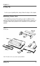
Chapter 1 Setting Up To set up your Apex80 printer, simply follow the steps in this chapter. Identifying Printer Parts First, see that you have all the parts you need. In addition to this manual, the printer box should contain the items shown in Figure 1-1.* The paper feed knob is packed into an indentation in the white foam material. Figure 1-1. Printer parts *Note: The tractor unit for your printer may be preinstalled.
In addition to the items in the box, you need a proper shielded cable to connect the printer to your computer. You may also need an interface board, which is necessary only for those computers that can’t use the Centronics® parallel interface. Your computer manual can tell you which cable you need and whether or not you require a special interface.
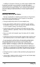
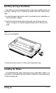
Installing the Paper Feed Knob Now that you have decided where to locate your Apex80 printer, the first step in setting it up is installing the paper feed knob. Follow these steps: 1. Locate the paper feed knob, which is packed into an indentation in the white foam material. 2. Insert the knob into the hole on the right side of the printer, as shown in Figure 1-2. Gently rotate the knob until it fits over the shaft. Figure I-2. Paper feed knob installation 3.
To install the ribbon, follow these steps: 1. Remove the lid at the front of the printer by lifting the handles. Removing the lid enables you to see the print head, which is shown in Figure 1-3. Figure 1-3. Print head Caution The power must be off when you move the print head because moving the print head when the power is on may damage your printer. Also, if you’ve been using your printer, be careful not to touch the print head because it becomes hot during use. Let it cool for a few minutes. 2.
4. Insert the cartridge by placing the black hooks on each side of the cartridge into the slots located inside the printer in the right and left front corners. Push down until the cartridge snaps into place. (See Figure 1-4.) Figure 1-4. Ribbon cartridge installation 5. Turn the knob on the cartridge in the direction of the arrow to tighten the ribbon. As you turn the knob, see that the ribbon slips down into its proper place between the print head and the ribbon guide.
Figure 1-5. Directing the ribbon 6. Replace the front lid by inserting its legs into the slots near the front corners of the printer. Lay the lid down and press to snap it into place. Replacing the Ribbon When your printing becomes light and you need to replace the ribbon, follow these steps: 1. Remove the front lid. 2. Grasp the ribbon cartridge handle and pull out the cartridge. 3. Follow the ribbon installation instructions above to insert the new ribbon cartridge.
Using Continuous-feed Paper The following section covers use of continuous-feed paper with your tractor unit. If you plan to use single-sheet paper, skip to the Using Single-sheet Paper section later in this chapter. The tractor unit for the Apex80 allows you to use paper with pin feed holes along the sides (continuous-feed paper). You can adjust the tractor unit to accommodate widths of paper ranging from 4 to 10 inches, including the pin feed holes.
Figure 1-6. Removing the tractor unit slot cover 3 Fit the paper rest into the slots along the top edge of the back of the printer and snap it into place. See Figure 1-7.
4. Pull the paper release lever forward. (See Figure 1-8.) The doublearrow icon in front of the lever marks the position the lever should be in for using continuous-feed paper (or for releasing paper). 5. Now install the tractor unit. First, hold the unit so that its black legs are facing downward, as shown in Figure 1-8. Figure 1-8.
6. In each tractor slot, located at each side of the paper slot, is a peg that fits into the notch on each of the rear tractor legs. Tilt the tractor back so that the rear notches fit over these pegs. See Figure 1-9. Figure 1-9. Installing the tractor unit 7. Then tilt the unit forward until the front legs snap into place. Loading continuous-feed paper Once the tractor unit is installed, load continuous-feed paper as follows: 1. Make sure that the printer is turned off. 2.
4. Using Figure 1-10 as a guide, pull the locking levers on each side of the pin feed holders forward so you can move the pin feed holders. Figure 1-10. Locking lever fur pin feed holder adjustment 5. Place the left holder approximately 3/4 of an inch from the far left position and then push the locking lever back to fasten that holder into place. Leave the other holder unlocked. 6. Open the pin feed covers as shown in Figure 1-1. Figure 1-11.
7. Feed the paper into the paper slot. Push and maneuver the paper through the slot until it comes up between the ribbon guide and the platen. 8. Pull the paper up until the top is above the pin feed holders. Fit the holes along the left edge of the paper over the pins in the left holder, as shown in Figure 1-12, and close the pin feed cover. Figure 1-12. Fitting the paper into the left pin feed holder 9.
For continuous-feed paper, move the edge guides to the far right and left positions on the paper guide. You won’t be inserting paper through the edge guides unless you use single-sheet paper. 2. Insert the legs of the paper guide into the slots behind the tractor unit, keeping the guide tilted backward as you do so. (See Figure 1-14.
3. When the legs are in the slots, lean the guide all the way back. The guide should rest atop the paper entering the printer, separating it from paper exiting the printer. Setting top of form Now you are ready to set the top of form position. Follow these steps: 1. Turn the paper feed knob to advance the paper until a perforation between pages is just below the top of the ribbon, 2. Now replace the front lid. Your printer should now be set up as shown in Figure 1-15. Figure 1-15.
Once you have set the top of form, each time you finish printing a document, push the ON/OFF LINE button to put the printer offline and then push the FORM FEED button once to advance the paper one sheet. This enables you to tear off your just-printed pages and leave th paper in the correct position to begin the next document. Note Make sure that the front lid is in place whenever you print. (Always snap the lid shut when replacing the lid.
Installing the paper guide Install the paper guide as follows: 1. If you have not already done so, install the edge guides on the paper guide by hooking the tab on the back of each guide over the top of the paper guide, as shown in Figure 1-13. Snap the bottom of each edge guide into place. 2. Hold the paper guide so that it is in an upright position. Then insert the legs of the guide into the slots on either side of the printer behind the paper slot, as shown in Figure 1-16. Figure 1-16.
3. Align the left side of the left edge guide with the guide mark on the paper guide. See Figure 1-17. You may later wish to adjust this edge guide depending on the margin setting in your application program. Figure 1-17. Guide mark for paper alignment Automatic paper loading Now you are ready to load single-sheet paper using the Apex80’s AUTO LOAD feature. To load paper automatically, just follow these steps: 1. Push back the paper release lever. (See Figure 1-16.
Figure 1-18. Apex80 ready for automatic paper loading 6. Press and release the AUTO LOAD button (the same button as the DRAFT/LINE FEED button). The paper is automatically loaded to the top of the page. 7. Push the ON/OFF LINE button so that the printer is ready to accept data. Note Make sure the front lid is in place whenever you print. (Always snap the lid shut when replacing the lid.) The front lid doubles as a paper bail, holding the paper against the platen, 8.
Reloading during printing When you print a document more than one page long using singlesheet paper, there are two ways your software can enable you to load a new sheet at the end of a page: l l If your software sends characters in a continuous stream, the printer stops printing when it reaches the bottom of the paper. When this happens, the ON LINE light goes off automatically.
Figure 1-19. Control panel There are four indicator lights and three buttons on the control panel. Indicator lights The indicator lights give you information on the printer’s status: l The POWER light glows green when the power is on. l The READY light glows green when the printer is ready to receive data. This light flickers somewhat during printing. l The PAPER OUT light glows red to indicate that the printer is out of paper or the paper is loaded incorrectly.
fully-formed characters for final copies or special purposes. NLQ is available in both Roman and Sans Serif fonts. The printout below shows the differences among draft, NLQ Roman, and NLQ Sans Serif so that you can compare the different styles and densities: See Chapter 4 for more information on these modes and ways to select them. l ON/OFF LINE. This button switches the printer between on line and off line status. l NLQ/FORM FEED.
2. Turn the power switch off, then hold down the DRAFT button on the control panel while you turn the power back on. The Apex80 begins printing letters, numbers, and other characters that are stored in its ROM (Read Only Memory) in draft mode. (If DIP switch 1-5 has been turned on, the test will be performed in NLQ mode, as in step 4 below.) 3. When printing starts, you can release the DRAFT button; the printing continues until you turn the printer off or until the printer runs out of paper. 4.
Connecting the Apex80 to Your Computer Now that the test pattern has shown that your printer is operational, it’s time to hook it up to your computer. Remember that computer systems communicate with printers in a variety of ways. If your computer expects to communicate through a Centronics parallel interface, all you need is the proper shielded cable. If your computer requires any other kind of interface, you also need an interface board.
3. Secure the plug to the printer with the wire clips on each side of the connector. Press the clips into the metal clasps at each side of the plug. These clips ensure that your cable will not be loosened or unplugged accidentally. 4. If your cable has a grounding wire, fasten it to the grounding screw below the connector. 5. Connect the other end of the printer cable to your computer.
Chapter 2 Using the Apex80 with Application Programs Now that you’ve set up and tested the printer, you need to start using it with your application programs. Printer Selection Menus Most application programs let you specify the type of printer you’re using so that the program can take full advantage of the printer’s features. Many programs provide an installation or setup procedure that presents a list of printers to choose from.
A quick test After setting up your application program, print a sample document to be sure the program and the Apex80 are communicating properly. If the document doesn’t print correctly, recheck the program’s printer selection and installation procedure. If you’re still having trouble printing, consult Appendix C. Computer - Printer Communication Computers and printers communicate by using codes to represent characters and commands.
The hexadecimal, or hex, system is based on units of 16 and is often used by programmers. Instead of using only the numerals 0 through 9, the hex system also uses the letters A through F. For example, the decimal numbers 9, 10, 11, and 12 are 09, 0A, 0B, and 0C in hex. Since the most frequently used hexadecimal numbers are between 0 and FF hex (0 to 255 in decimal), it’s common to write hexadecimal numbers that are less than 16 with a zero in front, as shown above.
Check the manual for your word processor to see if you can place printer commands in your text. If this is possible, use the Command Summary (Appendix A) in this manual to find the command, and use the manual for your word processor to find how to assign the command. If your Apex80 is not printing correctly, check both the printer and your word processor and do the following: l l l l Make sure you’ve selected the correct printer.
Table 2.1. Characters per line Normal Elite Condensed Condensed Elite 80 96 132 160 Therefore, if your spreadsheet asks the number of columns your printer can print, decide which mode you will use and supply the appropriate number from Table 2-1. Printer commands Unlike word processors, spreadsheet programs usually don’t let you change printer commands within a spreadsheet. Instead, one style or mode of printing is used for the whole spreadsheet.
If you’re using the program’s print facility, recheck the Command Summary to make sure you’re sending the correct commands. If you’re still having difficulty printing, check the troubleshooting section in your spreadsheet program’s manual or Appendix C of this manual. Graphics Programs The Apex80 is capable of producing finely detailed graphic images.
Sending printer commands with BASIC You can send printer commands with any programming language. The examples in this manual are written in BASIC, because BASIC is included with most computer systems. In most forms of BASIC, and in particular Microsoft® BASIC, the normal method of producing printed output is to use the LPRINT statement followed by the text to be printed enclosed in quotation marks, as shown below: 100 LPRINT "This text will be printed.
Chapter 3 SelecType The Apex80’s SelecType feature can produce four special typestyles: SelecType Operation Using SelecType is easy. You turn on SelecType and select a typestyle, then turn off SelecType and print. Turning SelecType on 1. Make sure that the printer is on line. 2. Hold down the ON/OFF LINE button and press the FORM FEED button. (See Figure 3-1.) When you turn on SelecType, a short beep sounds and the ON LINE light blinks to indicate that the printer is in SelecType mode.
Selecting typestyles In SelecType, each button has a function: l ON/OFF LINE selects typestyles. l FORM FEED sets the styles. l LINE FEED turns SelecType off. After turning on SelecType, follow these steps to select a typestyle: 1. Find the typestyle you want in Table 3-1. All of the typestyles listed in the table are available for draft mode. If you are in NLQ mode, only emphasized and elite are available. Table 3-1. SelecType modes 2.
When you press the ON/OFF LINE button to select an additional mode, start counting again where you left off. That is, if you have selected emphasized and wish to combine that with elite, press the ON/OFF LINE button three more times, not four, to select elite. For example, follow these steps to combine emphasized and elite: 1. Press the ON/OFF LINE button once to select emphasized. 2. Press the FORM FEED button. 3. Press the ON/OFF LINE button three more times to select elite.
l l If there are print codes in the document or file you are printing, those codes will override your SelecType settings. This seldom happens, since you usually won’t use SelecType with files that have such codes, but if your Apex80 follows the SelecType instructions for only part of a document, print codes in the document may conflict with the SelecType modes.
Chapter 4 Apex80 Printer Features You can obtain many different printing effects with the Apex80 printer, from arranging the printout on the paper to giving extra emphasis to particular words and phrases. This chapter shows you the features you may want to select with your software. Once you have read about the features, you can find their commands in the Command Summary. SelecType, as you know, controls the printing style of a whole document.
Print Size and Character Width To add greater variety to your documents, the Apex80 has two pitches and condensed printing. All can be selected either with SelecType or a software command, and software commands also offer another option: double-wide. Pitches The two pitches are pica and elite. Pica is 10 characters per inch (cpi) and elite is 12 cpi.
Widening or narrowing the characters also widens or narrows the spaces between words and letters. Because word processors usually create a left margin by printing spaces, you may need to change the number of characters on a line to keep the margins correct if you change widths. For example, a left margin of five pica characters is the same as one of six elite characters.
Using Different Character Sets The Apex80 incorporates a new character set: Epson Character Graphics. This set allows you to take advantage of the power of the Epson mode commands and still print out the character graphics used by IBM and compatible computers and by much commercial software. For example, if your word processor can include the characters to draw boxes and shade areas, you can produce some very professional effects. President and CEO V.P. V.P.
Page Layout and Other Commands The remaining commands in the Command Summary are not normally needed when using commercial software. You may need some of them if you are using a printer installation program provided with an application package, but most deal with features (such as tabs, margins, and line spacing) that are provided directly by commercial programs and are therefore only useful to you if you want to program the printer using a programming language such as BASIC.
Chapter 5 User-defined Characters The Apex80 has several hundred different characters stored in its ROM (Read Only Memory Although this number includes draft, italic, international, Character Graphics, and NLQ (Near Letter Quality) characters, sometimes you may want to have a few more. For those occasions when you need a special character or a few letters in a different typeface, the Apex80 allows you to create your own characters and print them just as if they were ordinary letters.
You can create any type of character. The only restriction is that the characters you define must follow the same rules that govern the rest of the characters printed by the Apex80. They must fit into an 11 x 9 matrix, no dot can overlap another, and either the top or the bottom row must be empty. Designing Process Suppose you want to print the scientific symbol for the planet Mercury. Although the Apex80 has a number of special symbols, that is not one of them.
the dots as large as you see them in the example on the left in Figure 5-2. If you draw them smaller, you may have overlapping dots without realizing it. Figure 5-2. Correct and incorrect designs overlapping dots dot on horizontal line If you do accidentally overlap dots, don’t worry. The program will still work, but only one of the dots will be printed. First definition program Once you have drawn your dots on the grid, type in the following BASIC program and run it.
200 FOR X=1 TO 9 210 LPRINT CHR$(F(X));:NEXT X 220 LPRINT CHR$(0)CHR$(0); 230 LPRINT "YOUR CHARACTER IN PICA: < < <" 240 LPRINT "IN DOUBLE-WIDE EMPHASIZED PICA: "; 250 LPRINT CHR$(27)"!*< < <(" 260 LPRINT CHR$(27)"!"CHR$(0) "YOUR DATA NUMBERS:" 270 FOR K=1 TO 9: LPRINT F(K);: NEXT K 300 LPRINT: END The next few sections explain the steps used to create the symbol for Mercury. First, Figure 5-3 shows the grid used to design the character. Figure 5-3.
To see program 1 produce the character in Figure 5-3, run the program and follow these instructions: 1. When the screen message asks what rows have dots in column 1, press Enter to indicate that no dots go in that column. 2. For column 2 (the vertical line) press 7, Enter, 5, and Enter again to indicate that you want dots in rows 7 and 5. Then press Enter alone to indicate that no more dots go in column 2. 3. For column 3 press 8, 6, 4, and 2, and Enter after each of them.
Figure 5-4. Using the bottom eight rows Second definition program Once the character looks the way you want it to, you can enter, modify, and run the next program. The program as listed creates the Mercury character, but you can use it for any characters you create if you make one or two changes, as explained after the program listing.
created more than one character, put the DATA numbers for each character on a separate line as you see in the example below: 210 DATA 112,8,0,138,116,138,0,8,112 220 DATA 56,68,146,40,130,40,130,68,56 Check your work by making sure there are nine numbers in each line and the numbers are separated by commas. Also make the change in line 100 explained below. Line 100 states K= 1; to define more than one character, use the total number of characters you are defining instead of the 1 in that line.
you use the grid and the programs in this section, however, you can design your own NLQ characters. NLQ grid Because the NLQ characters can use as many as 18 dots vertically and 12 dots horizontally, you plan your designs on a different grid than the one you used for draft characters. See Figure 5-5. Figure 5-5. Grid for NLQ characters On this grid you can use any numbered line or space. As you can see, that includes the bottom line and the line on the right side.
Each NLQ character definition requires 36 data numbers. Therefore, each vertical column must be divided into three sections for the calculation of data numbers. The process is not difficult once you get some practice using it. Figure 5-6 shows a single column to make clear how the data numbers are calculated. Notice that in designing NLQ characters circles are used instead of dots to make it easier to keep track of overlapping dots. Figure 5-6.
positions) and add the values of any dots that are used there. Finally, you look at the bottom group (two dot positions) and add together the values used there. If no dots are used in a group, the data number for that group is zero. All zeros must be entered in the DATA statements for the NLQ definition programs. Now you can learn how to use the NLQ character definition with a simple arrow design. Figure 5-7 shows the design drawn on a grid and the data numbers printed at the top or bottom of each column.
If you look at each column individually, you can see how the data numbers were calculated. First NLQ definition program Now type in and run the following program. It has the data numbers for the arrow design. For a character of your own, change the data numbers in lines 130-150.
10 J=l: IF J>3 THEN A=58 ELSE A=60 20 LPRINT CHR$(27)"x"CHR$(1) 30 FOR X=58 TO 63: LPRINT CHR$(X)" ";: NEXT X 40 LPRINT 50 LPRINT CHR$(27) :""CHR$(0)CHR$(0)CHR$(0) 60 LPRINT CHR$(27)"%"CHR$(1)CHR$(0); 70 LPRINT CHR$(27)"&"CHR$(0)CHR$(A)CHR$(A-1+J); 80 FOR Y=1 TO J 90 LPRINT CHR$(0)CHR$(12)CHR$(0); 100 FOR X=1 TO 36 110 READ C: LPRINT CHR$(C); 120 NEXT X: NEXT Y 130 FOR X=58 TO 63: LPRINT CHR$(X)" ";: NEXT X 140 DATA 4, 0, 0, 8, 0, 0, 16, 0, 0, 32, 0, 0 150 DATA 64, 0, 0, 255, 255, 192, 64, 0, 0, 32, 0, 0 16
Chapter 6 Introduction to Dot Graphics The dot graphics mode allows your Apex80 to produce pictures, graphs, charts, or almost any other pictorial material you can devise. Because many commercial software programs use graphics, you may be able to print pictures and graphs like the ones on this page and the next by simply giving your software a few instructions. The quickest and easiest way to print graphics on your Apex80 is to use a commercial graphics program.
If you use commercial software that produces graphics, all you need to know about dot graphics is how to use the software. If, on the other hand, you wish to do your own programming or merely wish to understand how the Apex80 prints graphics, read on. The Print Head To understand dot graphics you need to know a little about how the Apex80’s print head works. The Apex80's print head has nine pins. As it moves across the page, electrical impulses cause the pins to fire.
Dot patterns The Apex80’s print head is able to print graphics in addition to text because graphic images are formed on the Apex80 about the same way that pictures in newspapers and magazines are printed. If you look closely at a newspaper photograph, you can see that it is made up of many small dots. The Apex80 also forms its images with patterns of dots, as many as 240 dot positions per inch horizontally and 72 dots vertically.
To fire any one pin, you send its number. To fire more than one pin at the same time, add up the numbers of the pins and send the sum to the printer. Therefore, with these labels for the pins, you fire the top pin by sending 128. To fire the bottom pin, you send 1. If you want to fire only the top and bottom pins, you simply add 128 and 1, then send 129. By adding the appropriate label numbers together, you can fire any combination of pins.
The graphics command format There are several different graphics commands giving different horizontal dot densities and printing speeds. Because the format is almost the same for all the commands, however, the example here keeps things simple by using only the single-density graphics command, ESC K. In single-density graphics, there are 60 dots per inch horizontally. The command to enter single-density graphics mode is ESC K nl n2.
Graphics data After receiving a graphics command such as ESC K nl n2, the printer prints the number of codes specified by nl and n2 as graphics data, no matter what codes they are. This means that you must be sure to supply exactly the right amount of graphics data. If you supply too little, the printer will stop and wait for more data and will seem to be locked. The next data sent will then be printed as graphics, even if it is really text.
WIDTH statements Some software (including most versions of BASIC) automatically inserts carriage return and line feed codes after every 80 or 130 characters. This is usually no problem with text, but it can spoil your graphics. Two extra columns of graphics are printed in the middle of the ones you send, and are left over and printed as text. In some versions of BASIC you can prevent unwanted control codes in graphics by putting a WIDTH statement at the beginning of all graphics programs.
1. The computer is prevented from adding any extra characters by the WIDTH statement (line 100). 2. The line spacing is changed to 8/72 of an inch-the height of the dot patterns used in the program (line 110). 3. The program goes through the graphics commands the required number of times (lines 120 and 170). 4. A new graphics command is used for each line printed (lines 130160).
Table 6-1. Graphics modes Modes 4-6 in the table are special modes that alter the horizontal density to give proportions of a computer monitor (the CRT modes), or to match the vertical density so as to give round circles (the plotter mode). In two modes, high-speed double-density and quadruple-density, the print head cannot print two consecutive dots with the same pin, so that it can print dots in only half the possible dot positions in any one row.
A little experimentation should tell you whether the reassigning code can improve your graphics printouts. Designing Your Own Graphics This section takes you through the development of a graphics program. The example is not especially complicated, but it does include the same steps you would use for a more complex figure. You should plan your figure with dots on graph paper, but before beginning to place the dots, you must decide which graphics density you want.
Now look at the high-speed doubledensity design in Figure 6-3. It should point you in the right direction for your own work. Figure 6-3. Arrow design After plotting the dots on a grid, you calculate the numbers for each pin pattern by dividing the design grid into separate print lines. For the arrow design, the grid was divided into two lines, each seven dots high. Then each column was examined to calculate the graphics data. The results for the first line are shown in Figure 6-4.
The numbers for the second line were calculated in the same way. Once the numbers for the pin patterns are calculated, they are put in the program in DATA statements, separated by commas. The program works in a similar way to the last example. This time it selects 7/72-inch line spacing because only seven pins are used. Because the data is not repetitive, each column of graphics data is read from the DATA statements and sent to the printer. The design is 41 dot positions wide.
Appendix A Command Summary This appendix lists and describes all the commands available on the Apex80. The first part of this appendix lists all commands in numerical order and gives the page number where each is fully described. If you know which command you are looking for, consult the numerical list to find the page number where it is described.
For the following commands that use only 0 or 1 for the variable, either the ASCII cocks 1 and 0 or the characters 1 and 0 can be used: ESC S, ESC U, ESC X, ESC W, ESC S, ESC- , and ESC % For example, in BASIC you can turn on double-wide with either of these statements: LPRINT CHR$(27);"W";CHR$(1) LPRINT CHR$(27);"W";"1" The simplest type of command consists of a single character to be sent to the printer.
Control key chart Some application programs can use control key codes for decimal values O-27. The table below gives you the proper values. The Control Key column indicates that you press the control key at the same time you press the key for the letter or symbol in that column, For example, you press the control key and A at the same time to send the value 1. Some programs that use this system cannot use control-@, and many programs use the control keys for other purposes. Dec.
Commands in Numerical Order This section lists all the Apex80 commands, with their decimal and hexadecimal values. The numbers in the columns on the right are the page numbers in this appendix where a complete description of the command can be found.
ASCII Dec Hex Description ESC 4 ESC 5 ESC 6 ESC 7 ESC 8 ESC 9 ESC : ESC < ESC ? ESC @ ESC A ESC B ESC C ESC CO ESC D ESC E ESC F ESC G ESC H ESC J ESC K ESC L ESC M ESC N ESC O ESC P ESC Q ESC R ESC SO ESC Sl ESC T ESC U ESC W ESC Y ESC Z ESC ^ ESC a ESC b ESC e ESC f ESC k 52 53 54 55 56 57 58 60 63 64 65 66 67 67 68 69 70 71 72 74 75 76 77 78 79 80 81 82 83 83 84 85 87 89 90 94 97 98 101 102 107 34 35 36 37 38 39 3A 3C 3F 40 41 42 43 43 44 45 46 47 48 4A 4B 4C 4D 4E 4F 50 51 52 53 53 54 55 57 59 5A 5E 6
ASCII Dec Hex Description ESC 1 108 6C Set left margin ESC s 115 73 Turn half-speed mode on/off ESC t 116 74 Select character table ESC x 120 78 Select NLQ or draft A-6 Page A-16 A-8 A-26 A-19 Command Summary
Printer Operation Initialization Initialize Printer ESC @ Format: ASCII code: Decimal: Hexadecimal: ESC @ 27 64 1B 40 Comments: Resets the printer mode and clears the buffer of printable data on the print line preceding the command. Selection DC1 Select Printer Format: DC1 ASCII code: 17 Decimal: Hexadecimal: 1 1 Comments: Returns the printer to the selected state if it has been deselected by the printer deselect code (DC3).
Speed Turn Half-speed Mode On/Off ESCs Format: ASCII code: Decimal: Hexadecimal: ESC 27 1B s 175 73 n n n Comments: The following values can be used for n: (The characters “0” and “1” 1: Mode is turned ON. 0: Mode is turned OFF. can also be used.) Printing direction Select Unidirectional Mode (one line) ESC< Format: ASCII code: Decimal: Hexadecimal: ESC < 27 60 1B 3C Comments: Printing is normally bidirectional. This command selects unidirectional printing for one line only.
Disable Paper-out Sensor ESC8 Format: ASCII code: Decimal: Hexadecimal: ESC 8 27 56 1B 38 Comments: Turns off the paper-out sensor so that you can print to the end of a single sheet of paper. Enable Paper-out Sensor ESC 9 Format: ASCII code: Decimal: Hexadecimal: ESC 9 27 57 1B 39 Comments: Cancels ESC 8. Therefore, the printer beeper sounds and printing stops when the printer reaches a point approximately 3/4 of an inch from the end of the paper.
Beeper Beeper BEL Format: ASCII code: Decimal: Hexadecimal: BEL 7 0 7 Comments: Sounds the printer’s beeper. Data Control Carriage Return CR Format: CR ASCII code: 13 Decimal: Hexadecimal: 0D Comments: Prints the data in the buffer and returns the print position to the left margin. A line feed may be added if DIP switch 2-4 is ON or the AUTO PEED XT line on the parallel interface is held LOW.
Delete Character DEL Format: ASCII code: Decimal: Hexadecimal: DEL 127 7F Comments: Removes the last text character on the print line but does not affect control codes. Vertical/Horizontal Motion Form feeding Form Feed FF Format: ASCII code: Decimal: Hexadecimal: FF 12 0C Comments: Prints the data in the print buffer and advances the paper to the top of the next form according to the current page length.
ESC C 0 Format: ASCII code: Decimal: Hexadecimal: Set Page Length in Inches ESC C n NUL 27 67 0 1B 43 00 n n Comments: Sets the page length to n inches. The value of n must be from 1-22. The top of form position is set to the current line. ESC N Format: ASCII code: ESC Decimal: 27 Hexadecimal: 1 B Set Skip-over-perforation N 78 4E n n n Comments: The variable n is the number of lines skipped between the last line printed on one page and the first line on the next page.
Line feeding LF Format: Line Feed LF ASCII code: Decimal: 10 Hexadecimal: 0 A Comments: ‘When this command is received, the data in the print buffer is printed and the paper advances one line in the current line spacing. Select 1/8-inch Line Spacing ESC 0 Format: ASCII code: Decimal: Hexadecimal: ESC 0 27 48 1B 30 Comments: Sets the line spacing to l/8 of an inch for subsequent line feed commands. The 0 is the character zero and not ASCII code 0.
Select 1/6-inch Line Spacing ESC 2 Format: ASCII code: ESC 27 Decimal: Hexadecimal: 1 B 2 50 32 Comments: Sets the line spacing to l/6 of an inch for subsequent line feed commands. The “2” is the character two and not ASCII code 2. This is the default at power on. Select n/216-inch Line Spacing ESC 3 Format: ASCII code: ESC Decimal: 27 Hexadecimal: 1 B 3 51 33 n n n Comments: Sets the line spacing to n/216 of an inch for subsequent line feed commands.
Perform ESC J Format: ASCII code: Decimal: Hexadecimal: ESC J 27 74 1B 4A n/216-inch Line Feed n n n Comments: Advances the paper n/216 of an inch. The value of n must be from O-255. This command produces an immediate line feed but does not affect subsequent line spacing and does not produce a carriage return. Vertical tabbing Tab Vertically Format: ASCII code: VT 11 Decimal: Hexadecimal: 0 B Comments: Advances the paper to the next tab setting in the channel selected by ESC/.
ESC b Format: ASCII code: Decimal: Hexadecimal: Set Vertical Tabs in Channels ESC 27 1B b 98 62 c n1 c n1 c n1 n 2 n2 n 2 ... . . . . . . NUL 0 00 Comments: Functions the same as ESC B, except that the variable c selects a channel for the vertical tabs, which must be between O-7. Therefore, up to eight sets of vertical tabs can be set. The channels are selected by ESC /. To clear the tabs in channel c use ESC b c NUL.
ESC Q Set Right Margin Format: ASCII code: Decimal: Hexadecimal: ESC Q 27 81 1B 51 n n n Comments: Sets the right margin to n columns in the current pitch. This command clears previous tab settings and all previous characters in the print line. The minimum space between the margins is the width of one double-wide pica character.
Horizontal/Vertical Skip ESC f Format: ESC f ASCII code: 27 102 Decimal: 66 Hexadecimal: 1 B n n n s s s Comments: Prints spaces or line feeds without carriage returns. When n is 0, s spaces will be inserted up to a maximum of 127. If n is set to 1, s line feeds will be performed. Horizontal tabbing Tab Horizontally HT Format: ASCII code: H T 9 Decimal: Hexadecimal: 09 Comments: Advances the print position to the next horizontal tab setting.
Overall Printing Style Select NLQ or Draft ESC x Format: ASCII code: Decimal: Hexadecimal: ESC 27 1B x 120 78 n n n Comments: The following values can be used for n: (The characters “0” and “1” 0: Selects the draft mode. can also be used.) 1: Selects the Near Letter Quality (NLQ) mode. ESC k Format: ASCII code: Decimal: Hexadecimal: Select NLQ Font ESC 27 1B k 107 6B n n n Comments: This command affects only the Near Letter Quality (NLQ) mode, not draft.
Master Select ESC! Format: ESC ASCII code: 27 Decimal: Hexadecimal: 1B ! 33 21 n n n Comments: Selects any valid combination of the modes in the table below. The variable n is determined by adding together the values of the desired modes from the table. Table A-1.
Select Elite Pitch ESC M Format: ASCII code: Decimal: Hexadecimal: ESC M 1B 4D 27 77 Comments: Selects elite pitch (12 characters per inch). Select Condensed Mode SI Format: ASCII code: SI Decimal: 15 Hexadecimal: 0 F Comments: Prints characters at about 60 percent of their normal width. For example, the condensed pica mode has 17 characters per inch. ESC SI Format: Select Condensed Mode ASCII code: ESC Decimal: 27 Hexadecimal: 1 B SI 15 0F Comments: Duplicates the SI command.
Select Double-wide Mode (one line) SO Format: ASCII code: S O 14 Decimal: 0E Hexadecimal: Comments: Double-wide mode doubles the width of all characters. This mode is cancelled by a carriage return or DC4. Select Double-wide Mode (one line) Esc so Format: ASCII code: Decimal: Hexadecimal: ESC SO 27 14 1B 0E Comments: Duplicates the SO command.
Turn Double-wide Mode On/Off ESC W Format: ESC ASCII code: 27 Decimal: Hexadecimal: 1B W 87 57 n n n Comments: The following values can be used for n: (The characters “0” and “1” 1: The mode is turned ON. can also be used.) 0: The mode is turned OFF. Double-wide mode doubles the width of all characters.
Select Double-strike Mode ESC G Format: ASCII code: Decimal: Hexadecimal: ESC 27 1B G 71 47 Comments: Makes text bolder by printing each line twice, with the second printing slightly below the first. In NLQ the mode is not available but is not cancelled. ESC H Format: Cancel Double-strike Mode ASCII code: ESC Decimal: 27 Hexadecimal: 1 B H 72 48 Comments: Turns off the double-strike mode selected by ESC G.
Select Subscript Mode ESC S l Format: ASCII code: ESC Decimal: 27 Hexadecimal: 1 B S SOH 83 53 01 1 Comments: Prints characters about two-thirds of the normal height in the lower part of the character space. The ASCII code 1 or the character “1” can be used in this command. It is cancelled with ESC T. ESC T Format: ASCII code: Decimal: Hexadecimal: Cancel Superscript/Subscript ESC T 1B 54 27 84 Comments: Cancels either superscript or subscript.
Word Processing ESC a Format: ASCII code: Decimal: Hexadecimal: NLQ Justification ESC 27 1B a a 61 n n n Comments: The following values can be used for n: 0: Selects left justification. 1: Selects centering. 2: Selects right justification. 3: Selects full justification. The default setting is n = 0. Full justification (n = 3) is performed when the buffer becomes full or when one of the following is received: CR, VT, LF, FE The commands HT and BS are invalid except in n = 0 mode.
Select Italic Mode ESC 4 Format: ASCII code: ESC Decimal: 27 Hexadecimal: 1B 4 52 34 Comments: Causes characters from the italic character set to be printed. This command is valid even if the Epson Character Graphics set has been selected by ESC t or DIP switch 1-3, but character graphics cannot be italicized. ESC 5 Format: ASCII code: ESC Decimal: 27 Hexadecimal: 1B Cancel Italic Mode 5 53 35 Comments: Cancels the mode selected by ESC 4.
Select an International Character Set ESC R Format: ASCII code: ESC Decimal: 27 Hexadecimal: 1 B R 82 52 n n n Comments: See Appendix B for more information on international character sets.
User-defined Characters Note: See Chapter 5 for sample programs and full information on this topic. ESC & Define User-defined Characters Format: ASCII code: Decimal: Hexadecimal: ESC 27 NUL d1 d2 ... d n & 38 0 d1 d2 ... dn 1B 26 00 d1 d2 ... dn Comments: This command allows characters to be redefined in the currently selected mode. The variables dl and d2 must be between 58 and 63 (3A through 3F hex).
Graphics Note: See Chapter 6 for sample graphics programs. Select Single-density Graphics Mode ESC K Format: ASCII code: Decimal: Hexadecimal: ESC 27 K n1 75 n1 1B 48 n1 n2 n2 n2 Comments: Turns on eight-pin single-density graphics mode (60 dots per inch). The total number of columns = nl + (n2 x 256).
Select Quadruple-density Graphics Mode ESC Z Format: ASCII code: Decimal: Hexadecimal: ESC 27 Z n1 90 n1 1B 5A n1 n2 n2 n2 Comments: Turns on eight-pin quadruple-density graphics mode (240 dots per inch). The total number of columns = nl + (n2 x 256). Select Graphics Mode ESC * Format: ASCII code: Decimal: Hexadecimal: ESC 27 * 42 1B n1 n1 m m 2A m n1 n2 n2 n2 Comments: Turns on graphics mode m. See Chapter 6 for details on the available modes.
Select 9-Pin Graphics Mode ESC” Format: ESC ˆ ASCII code: 27 94 Decimal: Hexadecimal: 1B 5E m m m n1 n1 n1 n2 n2 n2 Comments: Turns on 9-pin Graphics Mode. For this command the variable m defines density of print (0 for single and 1 for double). The total number of columns = nl + (n2 x 256). This mode requires two data items for each column of print.
Appendix B Character Tables This appendix contains tables of the complete Apex80 character set, including the extra characters for the 13 Epson international character sets. The tables give a printout of each character and the codes in decimal and hexadecimal. The first two pages of the table cover the standard ASCII character codes from 0 to 127. The remainder of the table shows up to four characters for each code.
Table B-1.
Table B-1, continued Dec 32 33 34 35 36 37 38 39 40 41 42 43 44 45 46 47 48 49 50 51 52 53 54 55 56 57 58 59 60 61 62 63 Hex 20 21 22 23 24 25 26 27 28 29 2A 2B 2C 2D 2E 2F 30 31 32 33 34 35 36 37 38 39 3A 3B 3C 3D 3E 3F Char SP ! " # $ % & ' ( ) * + ' — .
Table B-1, continued Dec Hex 128 129 130 131 132 133 134 135 136 137 138 139 140 141 142 143 144 145 146 147 148 149 150 151 152 153 154 155 156 157 158 159 80 81 82 83 84 85 86 87 88 89 8A 8B 8C 8D 8E 8F 90 91 92 93 94 95 96 97 98 99 9A 9B 9C 9D 9E 9F B-4 Italic set NUL BEL BS HT LF VT FF CR so SI DC1 DC2 DC3 DC4 Italic w/ESC 6 à è Graphic set NUL ù é ò â ì ° ä à å £ i ¿ Ñ ñ ¤ Å å ç § ß Æ æ Ø BEL BS HT LF VT FF CR so SI DC1 DC2 DC3 DC4 ø ¨ Ä CAN EM Ö Ü CAN EM ä ESC Graphic w/ES
Table B-1, continued Dec Hex 160 161 162 163 164 165 166 167 168 169 170 171 172 173 174 175 176 177 178 179 180 181 182 183 184 185 186 187 188 189 190 191 A0 A1 A2 A3 A4 A5 A6 A7 A8 A9 AA AB AC AD AE AF B0 B1 B2 B3 B4 B5 B6 B7 B8 B9 BA BB BC BD BE BF Character Tables Italic set Italic w/ESC 6 SP SP ! " # $ ! % & " # $ % & ' ' ( ( ) * + ) , , Graphic set á í ó ú ñ Graphic w/E S C 7 á í ó ú ñ Ñ Ñ ¿ ¿ * ¬ ¬ + ½ ¼ ½ ¼ – – i i . .
Table B-1, continued Italic set Italic w/ESC 6 @ Dec Hex 192 193 194 195 196 197 198 199 200 201 202 203 204 205 206 207 208 209 210 211 212 213 214 215 216 217 218 219 220 221 222 223 C0 @ C1 C2 C3 C4 C5 C6 C7 C8 C9 CA CB cc CD CE CF DO D1 D2 D3 D4 D5 D6 D7 D8 D9 DA DB DC DD DE DF A B A C C D B-6 D E F G H I J K L M N O P Q R S T U V W X Y Z Graphic set Graphic w/ESC 7 B E F G H I J K L M N O P Q R S T U V W X Y Z [ [ \ \ ] ] ˆ ˆ — — Character Tables
Table B-1, continued Dec Hex 224 225 226 227 228 229 230 231 232 233 234 235 236 237 238 239 240 241 242 243 244 245 246 247 248 249 250 251 252 253 254 255 EO E1 E2 E3 E4 E5 E6 E7 E8 E9 EA EB EC ED EE EF FO F1 F2 F3 F4 F5 F6 F7 F8 F9 FA FB FC FD FE FF Character Tables Italic set ltalic w/ESC 6 ' ' a a b b c c d d e e f f g g h i j h k l k l m m n o o p q q r s s r t u v w w v x x y y z z { { / ˜ DEL Graphic w/ESC 7 p u / } set i j n t Graphic } ˜ Ø
International Character Sets Twelve character codes between 35 and 126 can represent more than one character each, depending upon the international character set you select. You can make the choice either by setting DIP switches 1-6 through 1-8 or by using the ESC R command. The table below shows all 13 character sets, together with the number to use with ESC R to select each one. The DIP switch combinations to select any of the first eight character sets are in Appendix D.
Appendix C Problem Solving and Maintenance This appendix approaches troubleshooting from several directions. The first section uses a columnar format to match solutions with problems. Other sections cover beeper error warnings, hexadecimal data dumping, coding and 7-bit solutions, and specific solutions for several popular personal computer systems. Problem/Solution Summary Possible problems are listed on the left and solutions on the right.
Solution Printing is patchy, faint, uneven, or intermittent Check that the ribbon is seated correctly If you have been using the ribbon for a long time or for a large amount of printing, it may need to be replaced. It is also possible for the print head to wear out if the printer is used frequently and for long periods at a time. See the instructions on replacing the print head at the end of this appendix.
Problem Strange things print in graphics mode Solution Some systems require a WIDTH statement. See your system documentation. Many computers have problems sending one or more of the codes between 0 and 13. Avoid any that affect your system if possible. Seven-bit computers cannot use the eighth pin (128). If you have a 7-bit computer and any of your graphics data numbers are larger than 127, change the design so that all numbers are less than 128.
Problem Solution Computer systems that monitor printer Can’t deactivate paper-out sensor with either DIP switch cable pin 12 ignore both ESC 8 and the 1-4 or ESC 8 setting of switch 1-4. These systems stop the printing when no paper is in contact with the paper-end detector (a small switch located behind the platen). Certain printer cables are designed to overcome this problem, or you can use a longer page as a backing sheet.
The hexadecimal numbers are the codes received by the printer, and the guide section helps you find a certain place in the list of codes. Each character in the guide section corresponds to one of the codes. If the code is for a printable character, that character is printed. If the code is for a non-printable character, such as ESC or the code for a line feed or carriage return, a dot is printed.
Some computer systems change one or more codes when sending them from BASIC to the printer. The ability of the Apex80 to dump in hexadecimal lets you determine which codes are creating problems for your system. A hex printout of a program shows you exactly what the printer is receiving, regardless of what the computer is sending. The following test program lets you check to see which codes, if any, are problems for your computer system.
There are four common approaches. First, you may be able to buy an alternative interface board for your system. This is the best solution for 7-bit system problems. Check with your dealer or call the Epson 800 number. The second approach is to use commercially available software that is specifically designed to overcome these coding problems. Consult your dealer or refer to current computer publications to see if a program for your computer system is available.
Apple ® II solutions Apple II computers pose two types of problems. The first is that the Apple II is an 8-bit computer, but its printer interface handles only seven bits. The second is that there is one problem code number: nine. The printer interface card furnished with the Apple II computer passes only seven bits to the Apex80, which means that you have a 7-bit system. Should you need an 8-bit system, the simplest solution is to purchase a new printer interface card from your dealer.
Here is the way to adjust the width when it is the only problem. Tell the computer that the print line is wider than 80 characters with this WIDTH statement: WIDTH "LPTl:", 255 The 255 is a special number that prevents the computer system from inserting a CR-LF into the line-unless, of course, there’s one in your program. The extra line feed—CHR$(l0)—that accompanies each carriage return—CHR$(13)—d oes not cause a problem unless you need to use CHR$(13) in a graphics program.
brush or cloth, and never use alcohol or a thinner to clean the printer because it could damage the print head and the case. Do not spray the inside of the printer with oil: unsuitable oils can damage the mechanism. If lubrication is needed, call the toll-free Epson number: 1-800421-5426. The print head Be particularly careful with the print head. Never move it when the printer is turned on. When the printer is printing, the print head becomes hot.
Figure C-1. Releasing the print head lock levers 6. Lift the print head from its position and carefully disconnect the flat cable from the print head, as shown in Figure C-2.
Figure C-2. Disconnecting the cable 7. Connect the new print head to the flat cable, and place the new print head in the head mount, as shown in Figure C-3. Be sure to tuck the flat cable into the cable support as shown in the figure.
Figure C-3. lnstalling the new print head 8. Move the head lock levers back to their original positions. Now your new print head is ready to use.
Appendix D Defaults and DIP Switches This appendix lists the default settings and lists and explains the settings of all the DIP switches. Default and Initialization Settings The Apex80 can be initialized (returned to a fixed set of conditions) in three different ways: when it is turned on, when it receives an INIT signal at the parallel interface (pin 31 becomes LOW), and when it receives the ESC @ command. The following conditions are always reset: l The print head returns to the home position.
DIP Switch Settings The Apex80 has twelve DIP (Dual In-line Package) switches that allow you to change many of the printer’s settings to suit your individual needs. The DIP switches are in two groups, mounted on the back panel, as shown in Figure D-1. Figure D-1. DIP switch 1-1 is the switch at the far left side and the one at the far right is DIP switch 2-4. You can easily reset the switches with a thin, pointed object such as a small screwdriver or the cap of a ballpoint pen.
The following tables describe the switches and their functions. The first two tables summarize the two groups of switches. The remaining table shows how to set the DIP switches for the available international character sets. Table D-1.
The DIP switch settings to select the different character sets are shown in Table D-3. Table D-3.
Appendix E Choosing and Setting Up Optional Interfaces This appendix contains information on Epson interfaces compatible with the Apex80 printer, instructions on choosing the right interface for a particular job, and instructions for installing internally mounted interface boards.
Installing an Interface Before installing an interface, you must remove the printer’s cover. WARNING Do not remove the cover unless the printer is turned OFF and disconnected because high voltages are present inside the printer when the power is on. Also, do not touch contacts on the circuit board of the printer because many of the components can be destroyed by the static electricity charge that may build up on your body. 1.
Figure E-1. Removing the cover 6. Slightly raise the upper case by its front. As you do this, be careful not to pull the flat cable out of the control panel in the upper case.
7. Disconnect the other end of the flat control panel cable from the main circuit board connector. See Figure E-2. Figure E-2. Disconnecting the control panel cable After you remove the case, follow the instructions below to insert the interface board. After you have inserted the board, replace the case by reversing steps 2 through 7.
Inserting the interface board 1. Locate the connector cover at the back of the upper case, shown in Figure E-3. Push it down and in, toward the inside of the printer, until it clicks. You need to move the cover to allow access to the new interface connector when the case is reassembled. Figure E-3. connector cover 2. The screw marked CG at the rear of the circuit board is the connection for the frame ground wire. Unscrew it and then use it to connect the frame ground wire as shown in Figure E-4.
3. Plug the interface board into the connector marked CN2 on the main circuit board of the printer. 4. Secure the board to the three supports with the screws provided, as shown in Figure E-5. Figure E-5.
5. Connect the frame ground wire to the FG terminal tag on the interface board, as shown in Figure E-6. Figure E-6. Connecting ground wire to FG terminal tag 6. Reassemble the printer, reversing the procedure described in steps 2 through 7 in the previous section.
Serial Interface Settings If you are using an optional serial interface, you may need to change the communications protocol of the printer or the computer for them to communicate properly. The protocol used by the printer is decided by one or two groups of DIP switches located on the serial interface board; the protocol used by the computer can probably be altered by a software command. It is essential that the printer and computer use compatible protocols.
Appendix F Technical Specifications This appendix contains the specifications for the Apex80, including the built-in parallel interface. Printing Printing method Impact dot matrix Printing speed 180 characters per second in draft elite 150 characters per second in draft pica 25 characters per second in NLQ pica Printing direction Bidirectional logic-seeking for text printing Unidirectional for graphics and by software command for text Character sizes All except superscript and subscript are 3.1 mm high.
Mechanical Ribbon Cartridge, black #8750 (uses the same ribbon as the Epson LX-800 and FX printers) Life expectancy (in characters, at 14 dots/character): 3 million MCBF 3 million lines (excluding the print head) MTBF 4,000 hours Print head life 200 million strokes per needle Dimensions and Weight Height (excluding tractor): Width (with paper feed knob): Depth: Weight (including tractor): 3.5 15.7 12.1 11.2 in. in. in. lbs. Electrical Voltage 120V AC Power consumption 70 VA maximum Frequency 49.
Environment Temperature Operation: 41° F to 95° F (5 C° to 35 C°) Storage: -22° F to 149° F (-30 C° to 60 C°) Humidity Operation: 10% to 80% without condensation Storage: 5% to 85% without condensation Shock Operation: Up to 1 G within 1 ms Storage: Up to 2 G within 1 ms Vibration Operation: Up to 0.25 G at up to 55 Hz Storage: Up to 0.5 G at up to 55 Hz Parallel Interface Connector pin assignments and a description of respective interface signals are shown in Table F-1. Table F-1.
Table F-1. Pins and signals continual Notes: 1. The column heading “Direction” refers to the direction of signal flow as viewed from the printer.
2. “Return” denotes the twisted-pair return, to be connected at signal ground level. For the interface wiring, be sure to use a twisted-pair cable for each signal and to complete the connection on the return side. To prevent noise, these cables should be shielded and connected to the chassis of the host computer or the printer but not at both ends. 3. All interface conditions are based on TTL level. Both the rise and the fall times of each signal must be less than 0.2 microseconds. 4.
Table F-2. Printing enabled/disabled signals and control conditions On Line (Indicator on) ON LINE ON LINE ON LINE OFF LINE SLCT IN LOW (SW . 2-1/interface) HIGH HIGH HIGH/LOW (no effect) DC1/DC3 (Data on/off contr.) DC1 /DC3 (no effect) DC1 RECV’D DC3 RECV’D DC1/DC3 (no effect) ERROR BUSY ACKNLG Printing (Disabled/enabled) HIGH HIGH/LOW HIGH HIGH HIGH/LOW HIGH/LOW ENABLED PULSED EA. CHAR. (normal cond.) PULSED EA. CHAR ENABLED PULSED EA. CHAR.
Index Command descriptions are not indexed here. For page references for specific commands, see pages A-4—6 or the Quick Reference card. Automatic paper loading, 1-17—19 Connecting printer to computer, 1-23—24 Continuous-feed paper, 1-2, 1-7—15 Control codes, 2-2. See also Commands Control keys, A-3 Control panel, 1-19—22 B D BASIC, 2-6—7 Baud rate.
F N Foreign language characters. See International character sets FORM FEED button, 1-21 Near Letter Quality (NLQ) mode, 1-20—22, 4-1 NLQ/Form Feed button, 1-21 G O Graphics, 2-6,6-1—12 ON LINE light, 1-20 ON/OFF LINE button, 1-21 H Head. See Print head Hexadecimal, 2-2—3 I Indicator lights, 1-20 Initialization, D-1 Interface board, 1-2. See also Interfaces, optional Interface, parallel, 1-2, 1-23, F-3—6 Interfaces, optional, E-1—8 International character sets, 4-4, B-8, D-3—4 Italics, 4-4.
S Sans Serif, 1-21,4-1 SelecType, 3-1—4 Self test, 1-21—22 Serial interface. See Interfaces, optional Service. See Toll-free number Single-sheet paper, 1-15—19 Software commands. See Commands Specifications, F-1—6 Spreadsheets, 2-4—6 Subscripts, 4-3 Superscripts, 4-3 T Technical specifications, F-1—6 Toll-free number, 2, C-1, C-10 Top of form, 1-14—15 Tractor unit, 1-7—10, 1-15.
Commands by Function The following list of commands is in the order used in the Command Summary (Appendix A). To find details of the command you want to use, refer to the page number in the right column.
DIP Switch Settings Table 3. International settings Table 1. DIP switch group 1 Switch number Function 1-1 Select condensed or normal characters Select slashed or unslashed zero Select character table Paper-out detection Select print quality Select international character set 1-2 1-3 1-4 1-5 1-6 1-7 1-8 Action when ON Action when OFF Character set Condensed Normal USA 0 Graphics Inactive NLQ 0 italics Active Draft See Table 3 Table 2.
Setting up Printer Features Graphics User-defined Characters EPSON AMERICA, INC. 2780 Lomita Boulevard Torrance, California 90505 Printed in Japan 87.