EPSON® DFX-8000 User’s Manual
FCC COMPLIANCE STATEMENT FOR AMERICAN USERS This quipment has been tested and found to.&& with @te limits for a class B digital device. pursuant to Part 15 of the FCC &da. ‘Yhaee limits pe designed to provide reasonable protection against harmful interference in a residential installation. This equipment generates, uses and can radiate radio frequency energy and, if not installed and used in accordance with the instructions, may. w, .wtorodioc~ca&uu.
IlWORTANT SAFETY INSTRUCTIONS 1. Readall of these instructions and save them for later reference. 2. Follow all warnings and instructions marked on the product. 3. Unphrg this product from the wall outlet before cleaning. Do not use liquid cleaners or aerosol cleaners. Use a damp cloth for cleaning. 4. Do not use this product near water. 5. Do not pbce this product on an unstable cart, stand, or table. The product may fall, causing serious damage to the product. 6.
10. If an extension cord’is used with‘& product, make sure that the total of the ampere ratings on the products piugged into the extension cord does not exceed’the extension cord ampere rating. Also, make sure that the total .of all products plugged into the wall outlet does not exceed 15 amperes. 11. Never puih objects of any kind into this product through cabinet slots as they may touch dangerous voltage points or short out parts that could result in a risk of fire or electric shock.
Contents About This Manual 1 Introduction 3 Chapter 1 Setting Up the Printer 1-1 Unpacking the Printer ................................................ Choosing a Place for the Printer .................................. Assembling the Printer ............................................... Testing the Printer .................................................... Connecting the Printer to Your Computer ..................... Setting Up Your Application Software ..........................
Selecting an International Character Set ........................ 3-47 Choosing a Character Table ........................................ 3-49 Data Dump Mode ..................................................... 3-51 Chapter 4 Software and Graphics 4-1 Enhancing Your Printing ............................................ 4-2 Graphics ................................................................. 4-10 User-defined Characters ..............................................
Chapter 9 Command Summary Using the Command Summary .................................... Commands in Numerical Order ................................... Epson ESC/P Commands Arranged by Topic ................. IBM Emulation Mode Commands Arranged by Topic.. .... 9-l Appendix A-l 9-2 9-5 9-9 9-41 Proportional Width Table . . . . . . . . . . . . . . . . . . . . . . . . . . . . . . . . . . . . . . . . . . A-2 . -6 Character Tables . . . . . . . . . . . . . . . . . . . . . . . . . . . . . . . . . . . . . .
About This Manual This user’s manual provides fully-illustrated, step-by-step instructions for setting up and operating the Epson DFX-8000 printer. It also includes information that you will need for your daily use of the printer. Chapter 1 shows you how to unpack, set up, test, and connect the printer. Be sure to read and follow the instructions in this chapter first. Inside the back cover of this manual are illustrations that identify the parts of the printer.
About This Manual Conventions used in this manual 61 WARNINGS must be followed carefully to avoid damage to your printer and computer. CAUTIONS must be followed to ensure that your printer operates correctly. Notes containimportant information and useful tips on the operation of your printer. Where to Get Help Customer support and service for Epson products are provided by a network of authorized Epson dealers and Customer Care Centers throughout the United States.
Introduction The Epson DFX-8000 printer is an advanced dot matrix printer designed for business applications. The printer combines high performance and reliability with a wide range of-f-es, including high speed printing and automatic paper handling.
Introduction l A micro-adjustment feature that allows you to feed the paper forward or backward to finely adjust the top of form, loading, and short tear-off positions. l l l An improved control panel design that lets you select almost any feature with a single button. Compatibility with the Epson ESC/P@ commands used by FX-850/1050 and DFX-5000 ,printers. An IBM@ emulation mode that provides compatibility with application programs written specifically for IBM printers.
Introduction l Paper Cutter (C815001) This option allows you to handle continuous paper more easily by cutting off printed documents for you. l Interface Boards You can use several optional interface boards to supplement the printer’s built-in parallel and serial interfaces. Chapter 5 provides guidelines for choosing the right interface and instructions for installing an interface board.
Introduction Coax and Twinax interface boards Two interface boards (Coax and Twinax) let. you use the DFX-8000 as a local printer fez an IBM mainframe or minicomputer. These boards connect directly to the printer and allow it to function as a local IBM printer without the addition of any other circuitry or components.
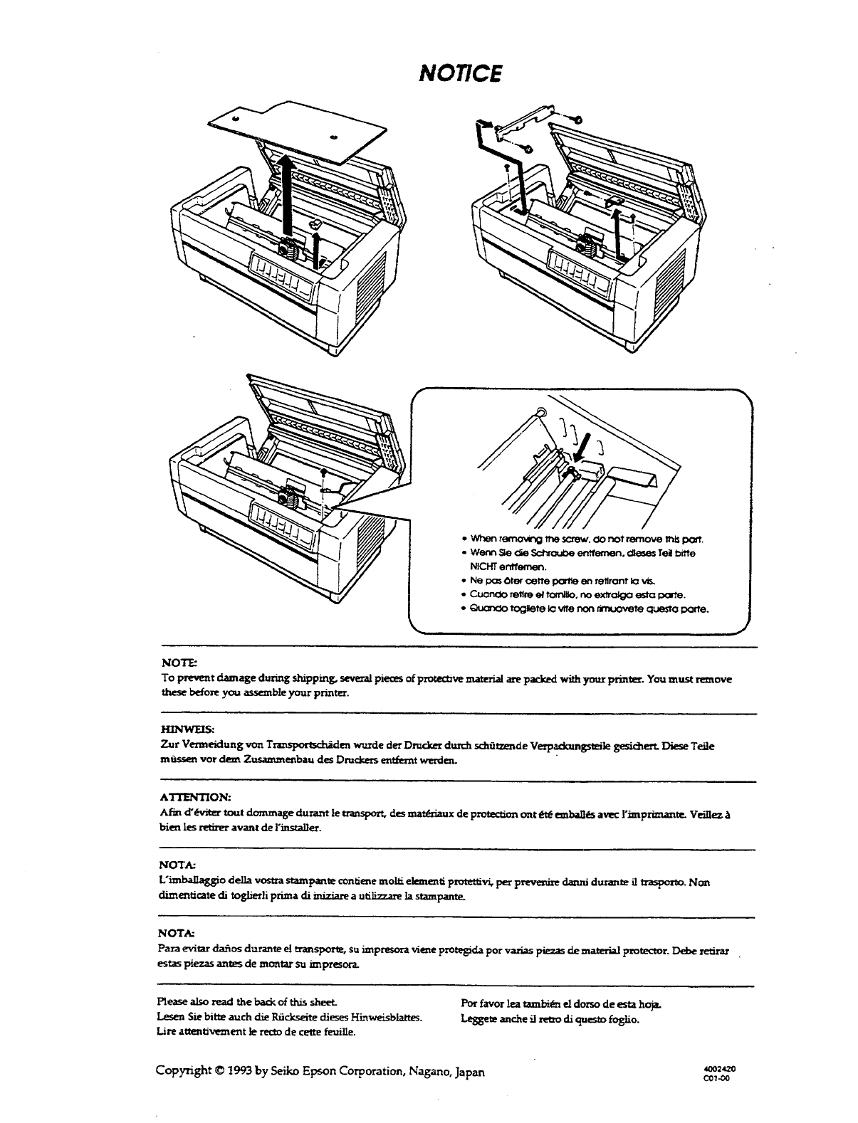
Chapter 1 Setting Up the Printer Unpacking the Printer ................................................ 1-2 Checking the parts ................................................. 1-3 Removing the protective materials ............................. 1-4 Choosing a Place for the Printer .................................. 1-7 Assembling the Printer ............................................... l - 9 Installing the ribbon cartridge ................................... l - 9 Testing the Printer ...................
Unpacking the Printer Because the printer weighs approximately 64 lbs. (29 kg), you should not lift or carry it alone.
Unpacking the Printer Checking the parts When you unpack the printer, make sure that you have all the parts shown below and that none have been damaged during transportation. power cable optional connector lock nuts ribbon cartridge cross-head screwdriver In some locations, the power cable may be attached to the printer.
Unpacking the Printer WARNING: There are several different versions of the printer designed for different electrical standards. The power supply voltage is shown on the label on the back of the printer. If the voltage shown is not correct for your country, contact your dealer. It is not possible to adjust the printer for use with different voltages. After you unpack the printer, save the packaging materials in case you ever need to transport your printer.
Unpacking the Printer 2. Use the enclosed cross-head screwdriver to remove the five screws and the two transport locking brackets from the inside of the printer. 3. Remove the print head protector, as shown below. Then lift up the paper bail and remove the piece of foam packing underneath it.
Unpacking the Printer 4. Using the enclosed cross-head screwdriver, remove the carriage guide support bar. WARNING: Be sure to remove all protective materials before you turn on the printer.
Choosing a Place for the Printer When you select a location for your printer, keep the following in mind: l l l l Place the printer on a flat, stable surface. Place the printer close enough to the computer for the printer cable to reach. Leave plenty of room around the printer for your front and rear stacks of continuous paper as well as your printed output. Use a grounded outlet; do not use an adapter plug. WARNING: Avoid locations that are subject to direct sunlight, excessive heat, moisture, or dust.
Choosing a Place for the Printer The illustration below shows a good printer location. Notes: If you plan to use a printer stand, follow these guidelines to select and set up the stand: The stand should be able to support at least 128 lbs. (58 kg), which is twice the weight of the DFX-8000 printer. Never use a stand that supports the printer at an angle. The printer should always be kept level.
Assembling the Printer After you’ve decided on the best place to set up your printer, you need to install the ribbon cartridge. Installing the ribbon cartridge Before installing the ribbon cartridge, make sure that the printer is not plugged into an electrical outlet. Remove the ribbon cartridge from its box and plastic wrapper and ‘then follow these steps to install the ribbon cartridge: 1. Open the top cover by lifting its front edge up and away from you.
Assembling the Printer 2.. Slide the print head to the exposed part of the paper bail as shown below. 3.. Remove the separator from the middle of the ribbon cartridge and discard it. Then detach the ribbon guide from the ribbon cartridge (but not fromthe ribbon) and turn the ribbontightening knob in the direction of the arrow to take up any slack in the ribbon.
Assembling the Printer 4. Hold the ribbon cartridge with both hands and lower it into the printer. Pulling the cartridge toward you, slide the hooks in the sides of the cartridge over the two corresponding pins in the printer. Then push the cartridge down into position until the other two hooks snap into place over the mounting pins in the Note: Press lightly on both sides of the cartridge to make sure the hooks are properly connected. 5..
Assembling the Printer 6. Slide the print head from side to side to make sure that it moves smoothly and that the ribbon is not twisted or creased. 7. Close the top cover.
Testing the Printer Now that your printer is fully assembled, you can use its built-in self test function to be sure the printer is working correctly before you connect it to a computer. You should perform this test to make sure that your printer was not damaged during shipping and that the ribbon is correctly installed. Before performing the self test, you need to plug in your printer and load paper. Plugging in the printer 1. Make sure that the printer is turned off. 2.
Testing the Printer WARNING: If the rated voltage and your outlet voltage r!!!b do not match, contact your Epson dealer. Do not plug in the power cable. 3. If necessary, connect the power cable to the AC inlet on the printer’s rear panel. 4. Plug the power cable into a properly grounded electrical outlet. !!9 1-14 WARNING: Whenever you turn off the power, wait at least five seconds before turning it back on. Rapidly switching the power on and off can damage the printer.
Testing the Printer Running the self test The self test can be run in draft or Near Letter Quality (NLQ) mode, depending on which button you hold down as you turn on the printer. 1. Be sure the printer is turned off. 2.. Open the front cover by lifting its bottom edge up and toward you.
Testing the Printer left 3. Release the sprocket lock levers on both the right and sprocket units by pulling each lever down. 4.. Slide the left sprocket unit all the way to the left. Lock it in place by pushing the sprocket lock lever up.
Testing the Printer 5. Now slide the right sprocket unit to approximately match the width of your paper. (Do not lock it in place yet.) 6.. Slide the two paper supports so that they are spaced evenly between the two sprocket units.
Testing the Printer 7. Open both sprocket covers. 8.. Be sure your paper has a clean, straight edge, and then fit the first four holes in the paper over the pins of both sprocket units. Then close the sprocket covers. (The side of the paper that you want to print on should be facing you.
Testing the Printer 9.. Slide the right sprocket unit so that the paper is straight and has no wrinkles. Lock the sprocket unit in place by pushing the sprocket lock lever up. CAUTION: Be sure the sprocket units are not too far apart. l a- If they pull your paper too tightly or if they tear the ed&s o f the paper holes, a paper jam may result. To remove any excess tension in your paper, release the right sprocket once and lock it again. 10. Close the front cover.
Testing the Printer WARNING: Before turning on the printer, be absolutely sure you have removed all protective materials. Turning on the printer while the print head cannot move may seriously damage the mechanism. 11. While holding d o w n the L I N E FEED button (for draft mode) or the FORM FEED button (for NLQ mode), turn on the printer. The POWERandPAPER OUT lights come on. Also, either the front or rear tractor arrow o n the PAPER SELECT indicate lights up.
Testing the Printer 12. Press the LINE FEED/LOAD button to load your paper. (If the paper does not load, the front tractor may not be selected. Press the FRONT/REAR button to select the front tractor. This loads the paper automatically.) 13. Press the ON LINE button to start the self test. (The ON LINE light does not go on.) A list of your printer’s DIP switch settings is printed first, followed by a series of characters. The self test continues until the paper runs out or you press the ON LINE button.
Testing the Printer 15. Press the FORM FEED button to advance the paper. Then open the paper separator cover (the back flap of the top cover) and tear off the paper at the perforation. 16. Turn off the e printer. WARNING: Whenever you turn off the power, wait at least five seconds before turning it back on. Rapidly switching the Power on and off. can damage the printer.
Testing the Printer Here are parts of typical self test printouts: High-speed draft mode Uw~~~ar::tc~r p:i. tc:h S h a p e a9 z e I”0 t a b l e (#OH-OFFH) l4wvnal Nat. slashed T. tnli.c ESC/F mode cs W1. ZW1. GWL- Normal draft mode Character pitch Normal Shal:)e of zern Not slashed CG table (SOH-OFFH) Italic ESC/F m o d e SWl* SWl* SWl* SWl* rox+,- ./0123456789: ; &~?IABCDEFGHIJKLMNOP[ ‘O#+,-. /0123456789r;<=>?CBCDEFGHIJKLMNOPOf ( If+,-.
Testing the Printer NLQ mode character D i t c h Normal Not slashed Solving any self test problems If the self test does not print properly, check the list of possible problems and solutions below. Also be sure there are no packing materials remaining inside the printer. The paper is jammed. Turn off the printer, remove the jammed paper, and then load fresh paper. See page l-15. The printer does not print. The printer sounds like it is printing, but nothing is printed.
Testing the Printer Problem Solution The printout is faint or uneven. The printout is faint. The ribbon may be worn out. A worn ribbon can damage the print head and should be replaced. Install a new ribbon cartridge as soon as possible. See page 6-4. Parts of printed characters are missing, as shown here: There is either too much slack in the ribbon or the ribbon is caught on something. Stop printing, turn off the printer, and reinstall the ribbon cartridge. See page 1-9.
Connecting the Printer to Your Computer If the self test printed correctly, you are now ready to connect your printer to the computer. Your DFX printer has two separate interface connections: a parallel interface and an RS-232C compatible serial interface. If you are not sure which one is required by your computer, check your computer manual. parallel interface serial interface If you have a suitable shielded cable, you should be able to connect the printer to most computers immediately.
Connecting the Printer to Your Computer The parallel interface Follow these steps to connect the parallel interface cable to the printer: 1. Turn off both the printer and computer. 2. Open the rear cover by grasping it by the handholds on each side and pulling it out and down.
Connecting the Printer to Your Computer 3. Plug the cable connector securely into the parallel interface (the socket on the left). WARNING: Do not plug more than one interface cable into the printer at one time. This may damage the printer. 4. Squeeze the wire clips together until they lock in place on either side of the connector.
Connecting the Printer to Your Computer 5. If your cable has a ground wire, connect it to the Pnter s ground connector. 6. Open the plastic clamp to the right of the parallel and serial interfaces by pressing down on its top tab. Insert the cable in the plastic clamp and close the clamp.
Connecting the Printer to Your Computer 7. Close the rear cover. CAUTION: Always close the rear cover before using the printer. 8. Plug the other end of the cable into the computer. (If there is a ground wire at the computer end of the cable, attach it to the ground connector at the back of the computer.
Connecting the Printer to Your Computer The serial interface Follow these steps to connect the serial interface cable to the printer: 1. Turn off both the printer and computer. 2.. Open the rear cover by grasping it by the handholds on each side and pulling it out and down.
Connecting the Printer to Your Computer 3.. Plug the cable connector securely into the serial interface (the socket on the right). WARNING: Do not plug more than one interface cable into the printer at one time. This may damage the printer. 4. If your cable connector has screws that you need to tighten using a screwdriver, open the top cover of the printer.
Connecting the Printer to Your Computer 5. Insert a screwdriver through the hole in the rear paper guide and fasten the screws of the cable connector. Note: If the screws that come with the cable do not fit into the connector lock nuts on the interface, replace the lock nuts with the optional lock nuts provided with the printer. 6. Close the top cover.
Connecting the Printer to Your Computer 7. If your cable has a ground wire, connect it to the printer’s ground connector. 8. Open the plastic clamp to the right of the parallel and serial interfaces by pressing down on its top tab. Insert the cable in the plastic clamp and close the clamp.
Connecting the Printer to Your Computer 9. Close the rear cover. CAUTION: Always close the rear cover before using the printer. 10. Plug the other end of the cable into the computer. (If there is a ground wire at the computer end of the cable, attach it to the ground connector at the back of the computer.
Setting Up Your Application Software Now that you have set up and tested the DFX-8000, you can start using it with your application software programs. Most software programs let you specify the type of printer you are using so that the program can take full advantage of the printer’s features. If your application program has an installation or setup procedure that lets you select your printer from a list of printers, choose the Epson DFX-8000 printer.
Setting Up Your Application Software If you plan to use IBM emulation mode, select one of the following printers, listed in order of preference: IBM Proprinter XL IBM Graphics printer IBM Printer Note: To use all the features of the DFX-8000, it is best to use a program with the DFX-8000 on its menu. If your software program does not list the DFX-8000, contact the software manufacturer to see if an update is available.
Paper Handling Using the Two-Tractor System .................................... Positioning the paper supply .................................... Loading paper onto the front tractor ......................... Loading paper onto the rear tractor ........................... 2-2 2-2 2-4 2-11 Switching between Front and Rear Tractors ................... 2-20 Changing the paper .................................................. 2-24 Printing on Special Paper ...........................................
Using the Two-Tractor System The DFX-8000’s paper handling system consists of a front and a rear push tractor. Both tractors are easy to load and operate, and both accommodate a wide variety of paper types, including labels and multi-part forms. The printer automatically adjusts to the thickness of your loaded paper, so you don’t need to set the paper thickness manually. You can use any width continuous paper, from 4 inches (101 mm) to 16 inches (406 mm) wide.
Using the Two-Tractor System CAUTION: Make sure that your stack of printed pages does not interfere with the rear tractor’s paper supply. front-loaded paper rear-loaded paper CAUTION: Be sure your printed output folds properly as it comes out of the printer. It should fold at the perforation between pages.
Using the Two-Tractor System Loading paper onto the front tractor The foIlowing steps show you how to load paper onto the front tractor. 1. Turn off the printer. 2.. Open the front cover by lifting its bottom edge up and toward you.
Using the Two-Tractor System Release the sprocket lock levers on both the right and left sprocket units by pulling each lever down. 4. Slide the left sprocket unit all the way to the left., Lock it in place by pushing the sprocket lock lever up.
Using the Two-Tractor System 5.. Now slide the right sprocket unit to approximately match the width of your paper. (Do not lock it in place yet.) 6.. Slide the two paper supports so that they are spaced evenly between the two sprocket units.
Using the Two-Tractor System 7. Open both sprocket covers. 8.. Fit the first four holes in the paper over the pins o f both sprocket units. (The side of the paper that you want to print on should be facing you.). Then close the sprocket covers. CAUTION: Make sure your paper has ‘a clean, straight edge before inserting it into the printer.
Using the Two-Tractor System 9.. Slide the right sprocket unit so that the paper is straight and has no wrinkles. Then lock the sprocket unit in place by pushing the sprocket lock lever up. CAUTION: Be sure the sprocket units are not too far apart. If they pull your paper too tightly or tear the edges of the paper holes, a paper jam may result. To remove any excess tension in your paper, release the right sprocket and lock it again. 10. Close the front cover.
Using the Two-Tractor System 11. Turn on the printer. The POWER and PAPER OUT lights go on. Also, either the front or rear tractor arrow on the PAPER SELECT indicator lights up, depending on which tractor was selected when the printer was turned off last, 12. Check the PAPER SELECT indicator to see which tractor is selected: l If the front tractor arrow is lit up, press the LINE FEED/LOAD button to load the paper.
Using the Two-Tractor System l If the rear tractor arrow is lit up, make sure the printer is off line and then press the FRONT/REAR button to switch to the front tractor. When the printer switches tractors, it also loads the paper automatically. 13. Press the ON LINE button to put the printer on line so it is ready to print. The paper is now loaded to the top of form position.
Using the Two-Tractor System Notes: l l Before you begin printing, be sure to check the page length and skip over perforation settings, and readjust the settings if necessary. See the sections on page length and skip over perforation in Cha#qr 3. If you open the top cover while the DFX is printing, the printer beeps four times, goes off line, and stops printing. To resume printing, close the top cover and press the ON LINE button.
Using the Two-Tractor System 2. Open the top cover by lifting its front edge up and away from you. 3. Open the rear flap at the back of the top cover.
Using the Two-Tractor System release the sprocket lock levers 4. Facing the front of the printer, on the rear tractor’s right and left sprocket units by Pushing each lever back. 5. Slide the left sprocket unit all the way to the left. Lock it in place by pulling the sprocket lock lever forward.
Using the Two-Tractor System 6. Now slide the right sprocket unit to approximately match the width of your paper. (Do not lock it in place yet.) 7. Slide the two paper supports so that they are spaced evenly between the two sprocket units.
Using the Two-Tractor System 8. Open both sprocket covers. 9. With the side of the paper you want to print on facing down, insert the paper through the opening at the rear of the printer. You may find it easier to load the paper by standing to the side of the printer. That way, you can feed the paper through the rear opening with one hand and pull it through with the other.
Using the Two-Tractor System CAUTION: Make sure your paper has a clean, straight edge before inserting it into the printer. 10. Fit the first four holes in the paper over the pins of the sprocket units. Then close the sprocket covers. 11. Slide the right sprocket unit so that the paper is straight and has no wrinkles. Then lock the sprocket unit in place by pulling the sprocket lock lever forward.
Using the Two-Tractor System CAUTION: Be sure the sprocket units are not too far apart. If they pull your paper too tightly or tear the edges of the paper holes, a paper jam may result. To remove any excess tension in your paper, release the right sprocket and lock it again. 12. Close the top cover and the rear flap. The paper is now loaded to the standby position. 13. Turn on the printer. The POWER and PAPER OUT lights go on.
Using the Two-Tractor System 14.. Check the PAPER SELECT indicator to see which tractor is selecte TC 11’ the rear tractor arrow is lit up, press the LINE FEED/LOAD button to load the paper. C U . l If the front tractor arrow is lit up, make sure the printer is off line and then press the FRONT/REAR button to switch to the rear tractor. When the printer switches tractors, it also loads the paper automatically.
Using the Two-Tractor System 15. Press the ON LINE button to put the printer on line so it is ready to print. The paper is now loaded to the top of form position. If it looks like the printing will start too high or low on the page, see the section on adjusting the top of form position in Chapter 3. Notes: l l Before you begin printing, be sure to check the page length and skip over perforation settings, and readjust the settings if necessary.
Switching between Front and Rear Tractors You can easily switch between paper loaded on the front tractor and paper loaded on the rear tractor with the FRONT/REAR button. The following steps describe the procedure for switching from the front tractor to the rear tractor, but you can follow the same steps to switch from the rear tractor to the front tractor. (To switch tractors when the optional pull tractor is installed, see Chapter 5.
Switching between Front and Rear Tractors 2. If there is no paper loaded in the rear tractor, load paper to the standby position. (See the section on loading paper onto the rear tractor in this chapter for instructions.) 3. Open the paper separator cover at the back of the top cover. 4. If you have a printed document still in the printer, OF excess paper that has been fed through the printer, use the short tearoff feature de&&d in Chapter 3 to tear off the document or excess paper.
Switching between Front and Rear Tractors WARNING: Always tear off the printed document and any excess paper that has been fed through the printer before switching tractors. Never feed more than one page backward 5. Close the paper separator cover. 6. Make sure the top cover is closed and then press the FRONT/REAR button to switch to the rear tractor. The-printer feeds the front-loaded paper back to the standby position and advances the rear-loaded paper to the top of form position.
Switching between Front and Rear Tractors 7.. Press the ON LINE button to put the printer on line so it is ready to print. Note: If you open the top cover while the DFX is printing, the printer beeps four times, goes off line, and stops printing. To resume printing, close the top cover and press the ON LINE button.
Changing the Paper The following steps describe the procedure for changing paper on the front tractor, but you can follow the same steps when you change the paper on the rear tractor. Before you start, make sure the printer is turned on and the front tractor is selected. (If you are changing the paper on the rear tractor, the rear tractor should be selected instead.) I! ! !9 WARNING: Never change paper using the following procedure if labels are already loaded in the printer.
Changing the Paper 2. If you have a printed document still in the printer, or excess paper that has been fed through the printer, use the short tearoff feature described in Chapter 3 to tear off the document or excess paper. WARNING: Always tear off printed documents before changing the paper. Never feed more than one page backward through the printer. 3. Press the FRONT/REAR button to switch to the rear tractor. The front-loaded paper automatically feeds back to the standby position.
Changing the Paper 4.. Open the front cover. (To change the rear-loaded paper, open the top cover and the rear flap.) 5.. Open the sprocket covers and remove the paper from the tractor.
Changing the Paper 6.. Load the new paper onto the front tractor as described in the section on loading paper onto the front tractor in this chapter. (If you are loading paper onto the rear tractor, see the section on loading paper onto that tractor.) 7. Close the front cover (or close the top cover and the rear flap).
Changing the Paper 8. Press the FRONT/REAR button to switch to the front (or rear) tractor and load the paper to the top of form position. Then press the ON LINE button -to -put the printer on line so it is ready to print. Note: If you open the top cover while the DFX is printing, the printer beeps four times, goes off line, and stops printing. To resume printing, close the top cover and press the ON LINE button.
Printing on Special Paper The DFX-8000 can print on various types of paper, including multipart forms and labels. It can also handle a variety of paper thicknesses, from thin paper to six-part forms. The printer automatically adjusts to the thickness and width of your paper. When you print on multi-part forms and labels, the positioning of your text on the page can be critical. For more. information on aligning your text, see the sections on adjusting the top. of form and printing positions in Chapter 3.
Printing on Special Paper Multi-part forms You can use continuous multi-part forms with up to four sheets, including the or@inal, on the rear tractor. On the front tractor, you can use forms with up ito six sheets. Be sure to use multi-part forms that meet the requirements listed in the section on paper in Chapter 8. WARNING: Never use multi-part forms thst have metal s t a p l e s . You load continuous multi-part forms the same way as you load any other type of continuous paper.
Printing on Special Paper When you use the paper memory feature described in Chapter 3, the DFX-8000 can print on multi-part forms that vary in thickness, such as forms with labels on them or forms that overlap slightly where they are.glued together. These forms are thicker in the label area and in the places where they overlap and are joined together, as shown below.
Printing on Special Paper Labels When using labels, always choose the type mounted on a continuous backing sheet with sprocket holes for use with a tractor. Labels should be used in t h e front tractor only. You load labels the same way that you load continuous paper. See the section on loading paper onto the front tractor earlier in this chapter.
Printing on Special Paper Before you print a large number of labels, print only one page of labels to make sure all the text is printed within the label area. WARNING: Since labels are especially sensitive to extreme temperature and humidity, always use them under normal operating conditions.
Chapter 3 Using the Printer Operating the Control Panel ....................................... ........................... ....................................... But&3 ................................................................ Other control panel features..................................... 3-2 3-2 3-4 3-6 Setting the DIP Switches ............................................ Changing a DIP switch setting.................................. The DIP switch tables ....................................
Operating the Control Panel The DFX-8000’s control panel gives you access to several powerful features. The control panel buttons let you control paper loading, primer settings, and more. The control panel indicator lights give you status information such as which mode the printer is in, which tractor is loaded with paper, and which tractor is ready to print. The following sections describe the functions of the control panel’s lights and buttons.
Operating the Control Panel PAPER OUT (red) On when the printer is out of paper. This light goes on whenever there is no: paper positioned behind the print head, even if there, is paper loaded on the tractors in the standby position. (The printer also beeps when it is out of paper.) ON LINE (green) On when the printer is on line and ready to receive and print data from the computer, Also, when the print head overheats, the ON LINE light blinks.
Operating the Control Panel Buttons The control panel buttons let you perform printer operations quickly and easily. Below is an Uustration of the control panel buttons and a description of their functions. OPOWER c1- a ON LINE c3 M FEED LINE FEED TEAR OFF FEED FORM - - - v, -. FRONT/REAR ON LINE This button controls the printer’s on line status. Press this button to put the printer on line or take it off line.
Operating the Control Panel LINE FEED/LOAD When the printer is off line, you use this button to load paper or to advance the paper after you load it. To advance the paper one line, press this button once. To advance the paper continuously, hold down the button. TEAR OFF The TEAR OFF button feeds the paper to the printer’s tear-off edge so you can tear off your document without losing the paper. normally lost between printing jobs.
Operating the Control Panel FRONT/REAR When the printer is off line, press this button to select the front or rear tractor. If you have been using paper loaded on one tractor, first remove the printed output before switching to the other tractor. When you switch tractors, the printer feeds the paper that is already loaded backward to the standby position and loads paper on the newly selected tractor. Other control panel f@ures The control panel also gives you access to several special functions.
Setting the DIP Switches The DFX-8000 has three sets of DIP (Dual Inline Package) switches located under a small cover below the front tractor. By changing the settings of these switches, you can control various printer features, such as the character set, the page length, and the printing speed. The DIP switch tables starting on page 3-11 describe the functions of the DIP switches.
Setting the DIP Switches 2.. Open the front cover. If there is paper loaded on the front tractor, remove it. 3. Open the DIP switch cover as shown below.
Setting the DIP Switches 4. Use a pointed instrument, such as the tip of a pen or pencil; to turn a switch on or off, A DIP switch is on when it is up, and off when it is down. CAUTION: Always make sure the printer is turned off before you change the DIP switch setti~&~. 5. Close the DIP switch cover.
Setting the DIP Switches 6.. Replace the paper and close the front cover, The new DIP switch settings take effect when you turn on the printer. The DIP switch tables The tables on the next page describe the functions of the DIP switches. The shaded boxes show the default or factory settings. See the page numbers listed on the right for more information about each feature.
Setting the DIP Switches DIP Switch 1 DIP Switch 2 1 SW 1 Description I ON I OFF 1 Page Default character set 2-5 - Interface type/parity 2-6 Seee table on page 3-13. 3-15 2-7 - Baud rate 2-8 Seee table on page 3-13. 3-16 The default setting for DIP switch l-3 varies depending on the country. ** When DIP switch 1-4 is on and the printer is in IBM emulation mode, the functions of DIP switches 1-3, 1-6, 1-7, 1-8 and 2-1 differ from those listed in this table.
Setting the DIP Switches DIP Switch 3 3-2 Page length l-inch skip over perforation Paper memory I 3-17 I 3-18 I Memory 2 3-20 1 Valid Multi-part forms with labels Valid Handshaking protocol 11 inches ON Ovf&laooinh m&i-oat-t forms Skip over binding l 12 inches ON 3-16 1 X-on/X-&f 3-16 I The default setting for DIP switch 3-2 varies depending on the country. International character set * The default settings for these DIP switches vary depending on the country.
Setting the DIP Switches Interface/Parity selection Baud rate selection When you select IBM emulation mode by turning on DIP switch 1-4, DIP switches l-3, 1-6, 1-7, l-8, and 2-l function differently than they do in Epson ESC/P mode. The tables below show the functions of these switches in IBM emulation mode. DIP switch functions in IBM emulation mode SW Q8scriptiin ON OFF 1-3 Automatic cafriaae return OFF ON 1-6 1-7 Default character table See table below.
Setting the DIP Switches The DIP switch functions This section describes the different features you can control with the printer’s DIP switches. Slashed zero When DIP switch l-2 is on, the printer prints slashed zeros(0). When the DIP switch is off, the printer prints open zeros (0). This feature is useful for clearly distinguishing between uppercase 0 and zero when printing documents such as program lists. Printer mode When DIP switch l-4 is on, the printer operates in IBM emulation mode.
Setting the DIP Switches draft mode, the DFX-8000 prints up to 800 characters per second at 10 cpi. Normal draft mode produces characters that are more fully formed than characters produced in high-speed draft mode. Note: High-speed draft mode is available only for 10 cpi printing. Also, underlining and double-wide are the only print enhancements that work in high-speed draft mode.
Setting the DIP Switches don’t know what type of interface your computer requires, check your computer manual. A&o check your computer manual to make sure your computer and printer have the same parity settings. Baud rate If your computer is set up for serial communication, you may need to set the baud rate in addition to selecting serial interface and setting the parity. The baud rate is the rate at which the printer receives data from the computer. DIP switches 2-7 and 2-8 control the baud rate.
Page Length When DIP switch 3-2 is off, the page length is set to 11 inches (27.94 cm). When the DIP switch is on, the page length is 12 inches (30.48 cm). Be sure to set the page lenth to match the paper you plan to use. Other page lengths can be set with the ESC C and ESC CO commands. See the Command Summary in Chapter 9.
Skip Over Perforation When DIP switch 3-3 is on, the printer inserts a one-inch margin between the last line printed on one;page and the first line printed on the next page. You can change the margin size with the ESC N command. See the Command Summary in Chapter 9.
Skip Over Perforation insert their own top over perforation feature only if your program does not provide them.
Using the Paper Memory Feature When you use multi-part forms that vary in thickness, use the paper memory feature so that the printer can compensate for the variations to produce high quality printing. Multi-part forms that vary in thickness include forms that have labels on them and forms that overlap slightly where they are glued together. Examples of these forms are shown below.
Using the Paper Memory Feature WARNING: When you use multi-part forms that vary in thickness, do not press the TEAR OFF, FRONT/REAR, or reverse-feeding (bottom) MICRO FEED button or a paper jam may result. To remove these forms, tear off the fresh supply at a perforation below the front tractor, take the printer off line, and press the FORM FEED or LINE FEED button to eject the remaining forms. Note: To use the paper memory feature, you need to reset some DIP switches.
Using the Paper Memory Feature Note: Be sure to remember or write down the memory area you use for each form. 3.. Use DIP switch 3-2 to set the page length. If you plan to use forms of a different page length, use software commands to set the page length after you finish saving the overlapping form information. Page length 11 inches DIP SW 3-2 I 12 inches 4. OFF ON I Turn on DIP switch 3-5 and turn off DIP switch 3-6.
Using the Paper Memory Feature 5.. Hold down both MICRO FEED buttons and turn on the printer. The printer saves the overlapping form information in the memory area you selected. When the information is saved, the printer beeps and goes off line. You can print on these forms even if you turn the printer off and then back on. To use other types of paper, see the section on loading paper format information from memory later in this chapter.
Using the Paper Memory Feature Saving information for multi-part forms with labels To save paper format and thickness information for multi-part forms with labels on them, follow the steps below. 1. Load the forms with labels onto the front tractor. (See the section on loading paper onto the front tractor in Chapter 2.) 2. Turn off the printer. Be sure to close the top cover. 3. Use DIP switch 3-4 to select the memory area where you want the printer to store the paper format and thickness information.
Using the Paper Memory Feature 6. Hold down both MICRO FEED buttons and turn on the printer. The printer beeps. Press the LINE FEED/LOAD button to load the forms. The printer loads and checks the forms. When the check is finished, the printer beeps continuously until you open the top cover in the next step. CAUTION: Do not go on to the next step before the printer beeps to tell you the check is finished. 7. Open the top cover.
Using the Paper Memory Feature CAUTION: Complete all the following steps before attempting any other operations, such as adjusting the top of form position. 8. Use the MICRO FEED buttons to adjust your paper’s position so that the top edge of the label is aligned with the horizontal red line on the clear plastic ribbon mask. 9. Move the print head by hand to align the vertical red line on the ribbon mask with the left edge of the label.
Using the Paper Memory Feature 10. Press the TOP OF FORM button. The printer beeps once. 0 TOP OF VORM 11. Use the MICRO FEED buttons to adjust your paper’s posftion so that the bottom edge of the label is aligned with the horizontal red line on the ribbon mask.
Using the Paper Memory Feature 12. Move the print head by hand to align the vertical red line on the ribbon mask with. the right edge of the label. Now the intersection of the red lines on the ribbon mask should be in the lower right comer of the label. 13. Press the TOP OF FORM button. The printer beeps twice. This tells the printer the label's location on the form. a TOP OF FORM Note: If the label’s location is still not correct, repeat the above procedure from step 8 on page 3-26.
Using the Paper Memory Feature 14. Close the top cover. The printer checks your paper’s thickness at various points and saves this information. (This takes the printer a certain amount time to complete.) When it is done, the printer -beeps and advances the form one page. The printer then goes off line. Notes: l If you close the top cover before setting the label’s location, the printer beeps several times to let you know an error has occurred.
Using the Paper Memory Feature Saving information for overlappb multi-part forms-with labels To save paper format and thickness information for multi-part forms ‘that overlap slightly and have ‘labels on them, follow the steps below. 1. Load the overlapping multi-part forms with labels onto the front tractor. (See the section on lqqdingpaper onto the front tractor in Chapter 2.) 2. Turn off the printer. 3.
Using the Paper Memory Feature Loading paper format information from memory After you save the information for your multi-part forms, you can load the forms you want to use, select the paper memory feature, and start printing. When you select the paper memory feature, the printer loads your form’s information from its memory. To select the paper memory feature, follow the steps below. 1. Load the multi-part forms you want to use onto the front tractor. 2. Turn off the printer. 3.
Using the Paper Memory Feature To load the information from memory area 2, hold down the bottom MICRO FEED button and turn on the printer. Note: After you load the information, the printer uses this information as the default setting when you turn on the printer. To use regular continuous paper after using multi-part forms that vary in thickness, hold down the FRONT/REAR button and turn on the printer.
Adjusting the Top of Form Position The top of form position is the position the printer feeds the paper to when it loads the paper or performs a form feed. This position is important because it determines where the printing begins on each page. If the printing is too high or low on the page, you can reset the top of form position by following the steps below. The printer remembers the new top of form position even after the printer is turned off, reset, or initialized.
Adjusting the Top of Form Position 1.. Make sure that the printer is tuned on and that it is off line. Also be sure the desired tractor is selected (the correspondillg tractor arrow should be lit). 2.. Press the TOP OF FORM button to enter top of form mode. The printer beeps, the TOP OF FORM light goes on, and the printer advances the paper slightly. CAUTION: Whenever you press the TOP OF FORM button and the TOP OF FORM light goes on, the printer sets a new top of form position.
Adjusting the Top of Form Position, 3. Open the top cover. 4. On the clear plastic ribbon mask, there is a red line that shows you where the printer will print the bottom edge of your first line of text. this position is based on the first printable line of text. If your software inserts a top margin of five lines, your text will actually be printed five lines below the top of form position.
Adjusting the Top of Form Position 5.. To exit top of form mode and save your new top of form position, press the TOP OF FORM button again. The printer beeps, the TOP OF FORM light goes off, and the printer feeds the paper backward to the printing position. (If you want to exit top of form mode. without saving your new top of form setting, press the ON LINE button instead of the TOP OF FORM button.) Close the top cover. 6. Press the ON LINE button to put the printer on line.
Adjusting the Printing Position If you need to adjust the printing positionin the middle of a page or document or adjust the top of form position when using labels, follow the steps below. When you move the printing position, you temporarily change the top of form position by the same amount. -For example, if you adjust the printing in the middle of a page so that it falls a half-inch lower, the next page also begins a half-inch lower.
Adjusting the Printing Position 2. Open the top cover. 3.. Press the top or bottom MICRO FEED button once to feed the paper forward or backward 1/216th of an inch, or hold down the button to move the paper continuously.. MICRO FEED WARNING: If you are using labels, use only the forwardfeeding (top) MICRO FEED button.
Adjusting the Printing Position 4. When you are finished, close the top cover and press the ON LINE button to put the printer on line.
Using Short Tear-Off When you are finished printing, you can use the short tear-off feature to feed the perforation of your paper to the printer’s tear-off edge. Then you can easily tear off the last printed sheet. When you resume printing, the printer feeds the paper backward to the top of form position. This saves the paper normally lost between documents. The steps below describe how to use the short tear-off feature.
Using Short Tear-Off 3.. Press the TEAR OFF button to enter tear-off mode. The TEAR OFF light goes on and the printer feeds the paper’s perforation to the printer’s tear-off edge. 4. If you need to adjust the position of the perforation so that it meets the printer’s tear-off edge, use the MICRO FEED buttons. You can press the top or bottom MICRO FEED button once to feed the paper forward or backward l/216& of an inch, or hold down the button to feed the paper continuously.
Using Short Tear-Off 5. Tear off the page using the tear-off edge on the printer’s top cover. 6. Press the TEAR OFF button to feed the paper back to the top of form position. Then press the ON LINE button to put the printer on line s o it is ready to print. (Or instead, just press the ON LINE button to feed the paper back and put your printer on line at the same time.) WARNING: Always tear off the printed document before 1 3-42 you feed the paper back to the top of form position.
Selecting Typestyles You can produce a wide range of typestyles by combining different character fonts, widths, and other enhancements. You can select typestyles using the DIP switches or software commands. For information on the available features, see the section on enhancing your printing in Chapter 4. Character fonts The DFX-8000’s draft font produces lower-resolution characters with fewer dots per character for high-speed printing. It is ideal for rough drafts and editing work.
Selecting Typestyles normal draft !"#6%&'0$+,-./0123456789:~~~~~?~~EC~EFGHIJ~ LMNOPQRSTUVW XY Z C \ I--’ abcdefghijklmnopq.rstuv wxyzI 1 3’+ We’ve just seen your excellent ad for in a recent back issue of W h a t i s t h e p r i c e schedule miniature zebras Trader’s Times. for quantities over one gross? NLQ Roman ! “#$%%-( )*+,- ./0123456789:;<=>?@ABCI)$FGHIJK LMN0PQRSTWWXYZC\l*,' abcdefghijklmnopqmtuv WXYZC I)- We've just seen your excellent ad for in a recent back issue of miniature.
Selecting Typestyles Character spacing ln normal draft and NLQ mode, you can select proportional spacing or a character spacing: of l O or 12 characters per inch (cpi) with software commands, In high-speed draft mode, only 10 cpi printing is available. (Ten cpi is the printer’s default character spacing.) ln the 10 and 12 cpi modes, each character gets an equal amount of space. In proportional mode, the spacing varies from character to character.
Selecting Typestyles Condensed mode Condensed mode reduces the size of characters to approximately 60% of their normal width, In condensed mode more characters fit on a line, which is useful for spreadsheets a n d other applications where you need to print the maximum amount of information on a page. Both 10 and 12 cpi printing can be condensed, but proportional printing cannot. To select condensed mode, turn on DIP switch l-l.
Selecting an International Character Set International character sets provide you with the characters and symbols used in other languages. In Epson ESC/P mode (which is selected when DIP switch l-4 is off), you can select one of eight international character sets by setting DIP switches l-6, l-7, and 1-8 according to the tabIe below. The table also shows the characters that differ in each international character set. Country DIP SW 1 ASCU code (hex) 23 24 40 5B 5C SD 5E 60 7B 7C 7D 7E 1-6 1-7 1-8 0 U.
Selecting an International Character Set In addition to the eight character sets, you can select with DIP switches, you can select the five international character sets shown below using the ESC R software command. See the Command Summary in Chapter 9 for more information.
Choosing a Character Table In Epson ESC/P mode (which is selected when DIP switch l-4 is off), you can turn off DIP switch l-3 to select the italics character table or turn on the switch to select the Epson Extended Graphics character table. The Epson Extended Graphics character table contains international accented characters, Greek characters, mathematic symbols, and graphics characters for printing lines, comers, and shaded areas.
Choosing a Character Table Epson Extended Graphics The Appendix provides the complete italics and Epson Extended Graphics character tables. ! CAUTIOb& Always be sure to turn off the printer before you change a DIP switch setting. After you set the DIP switches, turn on the printer to initialize the new settings. Notes: l The ESC 6 command tells the printer to print hex codes 80 to 9F and FF as characters-and the ESC 7 command tells the printer to use these hex, codes as control codes.
Data Dump Mode Data dump mode is a special feature that allows experienced users to find the cause of communication problems between the printer and application programs. In data dump mode, an exact printout of the codes reaching the printer is produced. To use data dump mode, follow these steps: 1.. Make sure that paper is loaded. (You can use the built-in tractor units or the optional pull tractor for printing in data dump mode.) If the printer is on, turn it off. 2.
Data Dump Mode 3. Next, run either an application program or a program you have written in any programming language. Your printer prints all the codes it receives in hexadecimal format, as shown below.
Data Dump Mode As an example of how to interpret a data dump printout, look at the first three hex codes on the second line of the printout sample (20 20 54). Each hex code 20 represents a space; the hex code 54 represents the letter T. Check the second line of the right column and you will find the letter T preceded by two spaces. The chart below interprets the first six nonprintable codes.
Chapter 4 Software and Graphics Enhancing Your Printing ............................................ Print quality and fonts ............................................ Character spacing .................................................. Character size ....................................................... Special effects and emphasis ..................................... Selecting typestyles with Master Select ....................... 4-2 4-2 4-3 4-4 4-5 4-8 Graphics ...................................
Enhancing Your Printing You can obtain a wide variety of printing effects with the DFX-8000 printer, from changing the number of characters printed per inch to using special effects or adding emphasis to selected words and phrases. This section gives you a sampling of the features you ina$ want to select with your software. For software control of these features, see the instructions for your application program or look up their specific commands in the. Command Summary in Chapter 9.
Enhancing Your Printing You can choose the print quality and NLQ fonts with software commands or DIP switches. However, high-speed draft can be selected only by setting DIP switch 2-2. (See the section on setting DIP switches in Chapter 3.) Note: High-speed draft is available only when 10 cpi printing is selected: T h e only print enhancements that can be combined with high-speed draft are underline and double-wide.
Enhancing Your Printing The following printout compares 10 cpi spacing with proportional spacing. This is 10 cpi printing. This is proportional printing. Note: High-speed draft is available only in 10 cpi. If you select 12 cpi or proportional spacing, the print speed temporarily switches to normal draft until 1 2 cpi or proportional spacing is turned off.
Enhancing Your Printing Condensed can be selected with.sokwar@c&nr&A or a ‘DIP switch. (See the section on settingDIP switches in Chapter 3.1 Even if you turn on candensed with the.DIP switch, you can,still turn it o f f w i t h a:software cammand. Condensed 10 cpi gives ys~ more characters os a line. cordsplled 12 cpi qea you CTCI more. Notes: l Both 10 and 12 cpi can be condensed, but proportional spacing cannot. l When condensed is selected in NLQ, NLQ is replaced by normal draft.
Enhancing Your Printing E m p h a s i z e d a n d &&ktrike prkting, , j Emphasized and double-striie printing can give text added distinction. In emphasized mode, the DFX-8000 prints each character twice as the print head moves across the paper, with the second character printed slightly to the right of the first. This process produces darker, more fully-formed characters. In double-strike mode, the print head goes over each line twice, making the text bolder.
Enhancing Your Printing Underlining The underline mode provides an automatic way of fully underlining any piece of text. Thimnode urdeh spaces, superscripts, and subscripts without a break. Most word processors take advantage of this feature, but .some programs use the underline character *stead. If this happens, check your prqqam for an underlining optiori. jR cn Superscripts and subscripts Superscripts and subscripts can be used for printing footnote numbers and mathematical formulas.
Enhancing Your Printing Selecting typestyles with Master Select Your printer has a special ESCape code called Master Select that allows you to choose many combinations of nine different printing lllOdC3: cpi l 12 cpi l l 10 l l l l proportional condensed emphasized l l double-strike double-wide italics underline For more information on sending ESCape codes to your printer, see Chapter 9.
Enhancing Your Printing For example, to print a title you may want to use double-wide 12 cpi characters and print them in double-strike mode. You would-add these three decimal numbers together to calculate the value of n. l2 cpi Double-strike Double-wide 1’ 16 32 - . . n = 49 After calculating the value of n, you would use the Master Select command to send the value to the printer. ASCII: Decimal: Hexadecimal: ESC 27 1B I 33 21 1 49 31 I Print quality and font selection are not part of.
Graphics The dot graphics mode allows your printer to produce pictures, graphs, charts, or almost any other pictorial material you can think of. Because many commercial software programs use graphics, you may be able to print pictures and graphs like the one on this page by simply giving your software a few instructions. The quickest and easiest way to print graphics on your printer is to use a commercial graphics program.
Graphics The print head To urtderstand dot graphics you need to know a little ‘about ‘how . your printer's print head works. As the print head moves across the page, electrical impulses cause the pins to fire. Each ‘time a pm fires, it strikes the inked ribbon and presses it against the paper to produce a small dot. As the head moves across the page, the pins fire time after time in different patterns to produce letters, number& or symbols.
Graphics Pin labels To tell the printer whiih,,.pins ,to.&e in each column, )rou ne&a numbering system that separately ident$fies ewh of the eight pins. Since there are 256 possible combinations of the eight pins in each section, you usethe ,*Geriri&‘b#km shiM W&y. ’ 1 : ir : 128 E 18 : 2 1I '-.'. .' To fire any one pin, you send its number. To fire more than one p‘in at tktim& time, add +p the nurtilk~ of the pins and ‘send’ the sum to the pfiter.
Graphics With this numbering system, any combinatkqn of the eight pins adds up to a decimal number between 0 and 255, and no numbers are dup&ate$. Beke $6~ C&I pd ‘,$I!& riumbeks in a grs)phics pr&rati, h&&er, ‘you n&d t&‘iuiow ~l$@-+i~t of the graphics commands* !-a’ . /‘. I’ ‘. i ,/‘, ” . ._ The graphics commands The gra&ics.m6de commands are quite different from most other commapds. For-most c$ #e c$her modes, a@~ ap. emphatied and doubkst&, one co-d turns&e modqpn a& anc#he.
Graphics Even in single-density graphics mode, one 8-inch line can accommodate 480 columns of graphics; jr( quadruple-density, almost 2OOO columns can fit on the same g-inch Bne. Since the &inter does not use decimal numbers larger than 255, the graphics mode command uses two numbers for reserving columns. To figure nl and n2, divide the total number of columns by 256. The result is ir2; the’ remainder is nl. Since the command is set up for two numbers, you must supply two even if you need only one.
Graphics Type and run the following program; be especially careful to include all semicolons. The program produces the printout you see below. 10 20 30 40 50 WIDTH"LPT1:".255 LPRINTCIiR$(27):"*":CHR$(O):CHR$(4O):CRR$(0); FOR Xtl TO 40 LPRINTCHR$(170): NEXT X :.--“..- Line 20 specifies single-density graphics mode and also reserves 40 columns for graphics. Line 30 begins a loop to supply 40 bytes of data.
Graphics Printing taller pattm The next examtile shows how several’ lines of graphics can be formed into a figure taller than eight dots. It uses programming techniques for producing textured or repetitive patterns. In the following program, the lines inside each pair of FOR and NEXT statements ara indented so that:you, can see how the program works; the spaces are not needed for the program to run.
Graphics 4.. A new graphics command-isused for each 1ine:printed (hnes 130 to 160). This part of the program is simihrto the last example, but two columns are printed each. time through the loop, making a total of 100. 5. The last important thing to do is to reset the printer to its initial settings, including the normal line spacing (line 180). Notice that the graphics command (& K)can be in effect for only one print line.
Graphics In the figure on the previous page, you can see the main rules for graphics design in the three densities: l l l In single-density, no dots can be placed on vertical lines. In double-density, dots can be placed on vertical lines, and they can overlap. In high-speed double-density, dots can be placed on vertical lines, but no dots can overlap. After choosing the desired density, you design your fiie by plotting dots on graph paper.
Graphics 12a I 64 32 16 8 4 2 1 1-1 I I I 1 1 1 I I 1 I , 1101111111111111111 44wwuMwa422l(I~t:8 8 8 0 I8 8184228 2 228200000000000000Ml44 The numberg for the second line were calculated in the same way. Once the numbeq for the pin patty are calculated, they are put in the pqgram. in. DATA statements, separated by commas. The following program is similar to the example on page 4-16. This program selects 7/7%inch line spacing because only seven pins are used.
Graphics When you run this program, it produces the following printout. If you want to see the fiiure in ‘otbr densities, change the Y in line 130 to L or Z. Individual graphics commands There are four indiv@ual graphf~‘tommands” that are very much the same as the ESC * co&arid, %ut each one works ‘for only ‘one graphics option. .Note that these c&ttri&ds contam ~one?&s ‘variable than the ESC .A* command because they do not .need to, select a. I. graphics option.
Graphics The letter s represents the command that you wish to we the assignment for (K, L, Y, or Z) and m is the number of the graphics option that you want to assign &I it,. For example, to w the ESC K command to use the CRT I graphics option, the command in BASIC is: LPRINT CHR!$(27);‘?“;X”;CHR$(Q) This is a quick way to change the aspect ratio of the design that you are printing. Cha@ing the graphics option will change the width without changing the height.
Userdefined Characters With thisaprinter, it is possible to define and print characters of your own design. You can design an entirely new alphabet or typeface, create characters for special applications such as mathematical or scientific symbols, or ,create graphic patterns with user-defined characters to serve as building blocks for larger designs. Below, you can see samples of typefaces created with the userdefined character function.
User-defined Characters Designing your characters Userdeked characters are like dot graphics because you send the- printer pm&e instructions on where you want each dot printed. In fact, planning a user-defined character is like planniqg a small dot graphics pattern. In this mode, you treat the printer as if it had a single column of nine pins. Design grids To design a draft character you use a grid that has nine rows and eleven columns as shown below. The following figure shows three of these grids.
User-defined Characters Sending information to your printer Once the -character is planned on the grid, you simply add the pin values for each column together, just as you do for graphics. The last step in defMng ,a character is to send this information to the printer. The command to define characters is relatively complex: ESC & 0 nl n2 al dz . . . dn You can define more than one character with a single command. The values nl and ti are the ASCII codes of the first and last characters you are defining.
User-defined Characters The following character definition program should help make this clear: 100 110 120 130 140 150 160 170 180 190 200 210 220 230 LPRINT CHR$f27) :“x”:CHR$(O) : LPRINT CHR$(27) ;"&";CHR$(O); LPR1NlY.V: LPRINT 'X$2$(136 1; FOR I=1 TO 11 READ A: LPRINT CHRS (A) : NEXT I LPRINT "@W@@" LPRINT CHR$(27,:"X";CHR$(l): LPRINT V0.W' LPRINT CHR$(27);"X":CHR$(O): LPRINT "eieo@" END DATA 32.80.168.84,42.84.168.80,32.0.
User-defined Characters A value of 136 is suitable for all characters that use the top eight pins, start in column 1, and finish in column 9. For a character of the same width, but printed with the bottom eight pins, al should be 8. For any other character, follow these rules to calculate al: 1.
User-defined Characters As you can see, both sets of characters (the original ROM characters that the printer normally uses and the user-defined character set) remain in the printer available for your use. The command to switch between the two sets is used in line 180 and 200. It is: ESC % n If n is equal to 0, the normal ROM character set is selected. If R is equal to 1, the userdefined character set is selected. You can also select one of the two character sets with DIP switch 2-1.
User-defined Characters Note: This command cancels any user-defined characters you have created. You must send this command to the printer before you define chaiacters. Also, check, that DW &it& 2-l is off before sending. this command to your priiiter. If you use this command at the beginning of a program, then define your special characters and select the userde&d charqcter set,, you can print with the user-defined character set as your norxqal chiiacter set.
Chapter 5 Using the Printer Options Pull Tractor ............................................................. Installing the pull tractor ......................................... Paper handling ...................................................... Removing the pull tractor ........................................ 5-2 Paper Cutter ............................................................ Installing the paper cutter ........................................ Paper handling .............................
Pull Tractor The optional pull tractor ( #8309) provides optimum continuous paper handling. The pull tractor is especially useful with continuous multi-part forms and labels. For best results, use the pull tractor along with one of the built-in push tractors, as described in ,this section. Installing the pull tractor To install the pull tractor, you need a cross-head screwdriver. The following steps show you how to install the pull tractor.
Pull Tractor 2. Use a cross-head screwdriver to remove the two screws securing the paper separator to the printer. Then lift the paper separator off the printer. 3.. Using the two screws you just removed from the printer’s original paper separator, install the paper separator that comes with the pull tractor.
Pull Tractor 4. Close the paper separator cover and open the top cover. 5. Holding the pull tractor with its gears to the left, fit the tractor’s front notches over the mounting shaft in the printer.
Pull Tractor 6. Open the paper bail using the tab on its right side. Then tilt the pull tractor back until its rear latches click into place over the printer’s rear mounting pins. 7. Close the paper bail and then close the top cover. Paper handling If you are using labels or multi-part forms with more than four parts including the original, use the pull tractor with the built-in front tractor. You can switch between the front and rear tractors at any time when you are using the pull tractor.
Pull Tractor Us@ the pull tractor with the front tractor The steps below show you how to load paper when you use the optional pull tractor with the printer’s built-in front tractor. 1. Load paper to the loading position on the front t+tor. (See the section on iw paper onto the front tractor &Chapter 2.) Then take the printer off line. 2. Open the top cover.
Pull Tractor 3. Press the FORM FEED or LINE FEED button to advance the paper over the pull tractor. FQMFEED WEFEE 4. Release both sprocket lock levers on the pull tractor by pulling them toward you. Then open both sprocket covers.
Pull Tractor 5. Adjust the sprocket units to match the width of your paper. 6. Slide the two paper supports so that they are spaced evenly ’ between ‘the two sprocket units.
Pull Tractor 7. Fit the paper's sprocket holes over the pins on the sprocket units and close the sprocket covers. CAWN: Qe.sure the sprocket units of the built-in front tractor’ and the optional pull trac@ are aligned. 8. If there is slack in the paper, or if the paper’s sprocket holes do not easily fit onto the tractor pins, press in the pull tractor knob and. tw~.it to adjust the position of the paper.
Pull Tractor 9. Slide the sprocket units so that the paper is straight and smooth, and then lock them into place. CAUTION Be sure the sprocket units are not too far apart. Ifthcppullyourpaper~tightlyorttar~e~ofthepaper holes, a paperjam may tit. To wmove anyextiess ten&on in your paper, release the right sprocket unit and lock it again. 10. Adjust the top of form position as described in Chapter 3.
Pull Tractor 11. Close the top cover. Make sure the edge of the first sheet emerges below the paper separator. 12. Press the ON LINE button to put the printer on line so it is ready to print.
Pull Tractor Using the pull tractor with the rear tractor This section describes how to load paper when you use the optional pull tractor with the built-in rear tractor. If paper is already loaded onto the rear tractor, follow steps 2 through 12 in the previous section to load paper ontqjthe pull tractor. If paper is not loaded onto the rear tractor, follow the steps below to load paper onto the pull tractor. 1. Turn on the printer and take it off line. Then open the top cover.
Pull Tractor 2. Pull the levers on the pull tractor toward you to release the pull tractor. 3. Tilt the trqctor forward with the front notches over the mounting shaft so that its sprocket pins rest on the meta! frame of the printer.
Pull Tractor 4. Load paper onto the rear tractor as described on page 2-11. 5. Open the paper bail usiq the tab on its right side. Then tilt the pull tractor back until the rear latches click into place over the printer’s rear mounting pins.
Pull Tractor 6. Follow steps 3 through 12 in the previous section to load the paper onto the pull tractor. Removing the pull tractor Follow these steps to remove the pull tractor. You will need a crosshead screwdrkr and the paper separator that origin&Ily was installed on the printer. 1. Turn off the printer. Then open the top cover and remove any paper loaded on the pull tractor.
Pull Tractor 2.. Pull the levers on the pull tractor forward to release the pull tractor. 3.. Tilt the p.uJl tractor forward, and then lift it up and out of the printer.
Pull Tractor 4. Close the top cover and open the paper separator cover. 5. Using a cross-head screwdriver, remove the paper separator that came with the pull tractor.
Pull Tractor 6. Using the two screws you just removed from the paper separator that came with the pull tractor, reinstall the ongmal paper separator. 7. Close the paper separator cover.
Paper Cutter The optional paper cutter (C815001) makes using continuous paper easier by cutting off your printed documents for you. When you use the paper cutter, be sure to set. the page l&ngth to match your paper. Installing the paper cutter The steps below show you how to install the paper cutter. You will need a cross-head screwdriver. WARNING: Do not use multi-part forms that vary in thickness with the optional paper cutter.
Paper Cutter 1. Turn off the printer and open the paper separator cover. 2. Use a cross-head screwdriver to remove the two screws securing the paper separator to the printer. Then lift off the paper separator. Store the paper separator and screws for your later U%e.
Paper Cutter 3. Close the paper separator cover and open the top cover. 4. Hold the paper cutter by its handle with the connector facing to the right. Then lower the paper cutter into the space at. the back of the printer, guiding the pins on the sides of the paper cutter into the notches in the printer. 5. After the paper cutter is in place, tilt the paper cutter handle forward. Then close the top cover.
Paper Cutter 6.. Open the rear flap and remove it by lifting up to pull the pegs on the rear flap out of the notches at the back of the printer. Then plug the paper cutter’s connector securely into the connector inside the printer. 7.. To replace the rear flap, fit the pegs on the rear flap into the notches at the back of the printer. Then dose the rear flap.
Paper Cutter This section describes how to use the paper cutter with your continuous paper. When you use the paper cutter, you need to set the page length to match your paper. Cutting off a printed document To cut off a printed document, follow the steps below: 1.. Be sure that the printer is turned on and that it is off line. 2. Press the TEAR OFF button. The printer advances the paper so that the perforation at the end of the last printed page is near the cutting line of the paper cutter.
Paper Cutter 3. If you loaded new paper onto the current tractor since the host time you cut off a document, you may need to adjust the cutting position. Open the paper separator cover and use the MICRO FEED buttons to adjust the cutting position with the cutting line. Then close the paper separator cover. Note: You,can set the cutting position, from 0.1 inches (3.0 mm) to 1.0 inches (25.4 mm) below the perforation at the end of the last printed page. The factory setting of the cutting position is the 0.
Paper Cutter 5.. Press the ON LINE button to put the printer on line so that it is ready to print. Note: The next printing position after cutting the paper depends on the cutting position and the top qf form position, as described below. When the cutting position is above the top of form position, the printer starts printing at the top of form position on the same page.
Paper Cutter When the cutting position is below the top of form position, the printer starts printing at the top of form position on the next page. n 0 : : : : : : : :0 : : 8 : :0 : 0 -top of form position cutting position 0 0 0 : : ------------m-e- 0 printing position - i WWF G +-top of form position : 8 0 Switching tractors To switch tractors when the paper cutter is installed, fallow the steps below: 1. Be sure that the printer is turned on and that it is off line.
Paper Cutter 2. Press the FRONT/REAR button to switch to the other tractor. The printer cuts off the printed document, feeds the paper on the tractor backward to the standby position, and then advances the paper on the other tractor to the loading position. 3. Press the ON LINE button to put the printer on line so that it is ready to print.
Paper Cutter Note: You can use the ESC EM printer command to change tractors only when the paper cutter is installed. For more information about this command, see the Command Summary in Chapter 9. CAUTION: When you load paper on the tractor, be sure that the first page is tom off exactly at the perforation, and the first four holes in the paper fit over the sprocket unit pins. Removing the paper cutter To remove the paper cutter, follow the steps below.
Paper Cutter 3. Open the rear flap and remove it by lifting up to pull the pegs on the rear flap out of the notches at the back of the printer. Then unplug the paper cutter’s connector from the printer. 4.. To replace the rear flap, fit the pegs on the rear flap into the notches at the back of the printer. Then close the rear flap.
Paper Cutter 5.. Open the top cover. Grasp the handle on the paper cutter and lift the paper cutter up and out of the printer. 6.. Close the top cover and open the paper separator cover.
Paper Cutter 7. Using a cross-head screwdriver, reattach the paper separator. 8. Close the paper separator cover.
Interface Boards You can use optional interface boards to supplement your printer’s built-in serial and parallel interfaces.
Interface Boards Compatible interfaces The following table lists Epson interfaces that are compatible with the DFX-8000. Some of these interfaces may not be available in your country or region and some may be no longer available. Name Number #8143 #8148 #8165 l New Serial interface board’ Intelligent serial interface board Intelligent IEEE-488 interface board Coax interface board Twinax interface board For more information on the New Serial interface (#8143), see page 5-39.
Interface Boards 1. Turn off both your printer and computer. 2. Open the rear cover.
Interface Boards 3.. Disconnect the printer cable from the printer and the computer. Then unplug the power cable from the electrical outlet and from the back of the printer. CAUTION: When you install an optional interface board, 4.. If the interface board comes with an FG (frame ground) wire that is not already attached to the board, attach the wire as shown below on the right.
Interface Boards 5. Plug the cable’s connector securely into the interface board. If the connector has tightening screws, use a screwdriver to secure the cable to the interface board. If the connector has clamps instead, squeeze them together to secure the cable to the interface board. Note: If the cable’s connector does not have tightening screws, you do not need to plug the connector into the board before you install it. 6..
Interface Boards 7. Use a cross-head screwdriver to secure the board with the four screws. 8. Remove the screw from the CG (chassis ground) connector on the printer. Then use the cross-head screwdriver to connect the round end of the FG wire from the interface board to the CG connector .
interface Boards 9.. Plug a suitable cable securely into the interface board, if you have not done so already. (If the cable connector has screws, you need to plug the cable into the board before you install the board. See step 5 on page 5-36.) 10. Secure the cable using the plastic clamp on the left.
Interface Boards 11. Close the rear cover. CAUTION: Always be sure the rear cover is closed when you use the printer. #8143 New Serial interface board If you use an optional interface, you may need to change the communications protocol of the printer or the computer so that they can communicate properly. In most cases, you should see your optional interface manual or computer manual to match the computer with the interface.
interface Boards Selecting a baud rate The range of baud rate settings for the #8143 interface depends on whether your printer’s input buffer is on or off. You can select baud rates from 75 to 19,200 bps (bits per second). When you set the baud rate, use the bit rate selection table for printers with buffers in the #8143 interface manual.
Chapter 6 Maintenance Cleaning the Printer . . . . . . . . . . . . . . . . . . . . . . . . . . . . . . . . . . . . . . . . . . . . . . . . . . 6-2 01 1 Replacing the Ribbon . . . . . . . . . . . . . . . . . . . . . . . . . . . . . . . . . . . . . . . . . . . . . . . . .6-4 Transporting the Printer ,..............,.............................
Cleaning the Printer To keep your printer operating at its best, you should clean it thoroughly several times a year. The following steps show you how to clean the printer. 1. Turn off the printer and close all of its covers. 2. Using a soft brush, carefully remove all dust and dirt.
Cleaning the Printer 3. If the outer case is dirty or dusty, clean it with a soft, clean cloth dampened with mild detergent dissolved in water. Keep all of the covers closed to prevent water from getting inside the printer. WARNINGS: l l l l Never use alcohols or thinners to clean the printer. These chemicals can damage the printer components as well as the case. Be careful not to get the printer mechanism or electronic components wet. Do not use a hard or abrasive brush.
Replacing the Ribbon When your printing becomes too faint, you need to replace the ribbon. Use only the # 8 7 6 6 standard Epson replacement ribbon cartridge for the DFX-8000. The steps below show you how to replace. the ribbon. 1.. If the printer is on line, press the ON Ll!lE button to take it off line. Then turn off the printer and open the top cover. Note: Make sure that the printer is off line before you turn it off.
Replacing the Ribbon 2. Slide the print head to the exposed part of the paper bail, as shown below. Lift the ribbon guide off the print head. 3. Pull up on the inside edge of the ribbon cartiidge to release it from the printer’s mounting pins. Then remove the cartridge by lifting it up and away from you. CAUTION: Be sure not to pull on the flat cable beneath the ribbon cartridge when you remove the catidge.
Replacing the Ribbon 4. After you unpack the new ribbon cartridge, remove the separator from the ribbon cartridge and discard it. Then detach the ribbon guide from its holder on the ribbon cartridge (but not from the ribbon). Turn the ribbon-tightening knob to remove any slack in the ribbon. 5.. Hold the ribbon cartridge with both hands and lower it into the printer. Pulling the cartridge toward you, slide the hooks in the sides of the cartridge over the two corresponding pins in the printer.
Replacing the Ribbon 6. Fit the plastic ribbon guide onto the metal pins on each side of the print head. The smaller end of the guide should be on top, with it angled edge toward the platen. Turn the ribbontightening knob to remove any slack in the ribbon. 7. Slide the print head from side to side to make sure that it moves smoothly. Also check that the ribbon is not twisted or creased.
Replacing the Ribbon 8. Close the top cover.
Transporting the Printer If you need to transport your printer some distance, carefully pack it in the original box and packing materials. The steps below show you how to pack your printer. 1. Turn off the printer and remove any paper loaded in the printer. If any printer options are installed, remove them as described in Chapter 5. I!!!3 WARNING: Be sure to turn off the printer before you unplug the power cable in the next step. 2..
Transporting the Printer 3.. Open the rear cover and disconnect the interface cable from the printer and the computer. 4. Close the rear cover.
Transporting the Printer 5. Open the top cover and slide the print head to the exposed part of the paper bail, as shown below. Lift the ribbon guide off the print head, and then remove the ribbon cartridge. 6. Using a cross-head screwdriver, reattach the carriage guide support bar and the two locking brackets.
Transporting the Printer 7. Lift up the paper bail and place the piece of foam packing underneath it, as shown below. Then insert the plastic print head protector. 8. Close the top cover. 9.. Replace the packing materials and put the printer in its box. WARNING: Even when you need to carry the printer only a short distance, do not carry it by your&. The printer should always be carried by two people holding the printer at the bottom.
Chapter 7 Troubleshooting Problems and Solutions .............................................. 7-2 Power Supply .......................................................... 7-3 Printing................................................................... 7-4 Paper Handling ........................................................ 7-13 Options ...................................................................
Problems and Solutions This chapter describes potential problems and their likely solutions. If you encounter a problem, look for it in the list below and see the appropriate page for the solution. Power supply l Power is not being supplied to the printer. See page 7-3. Printing l l l l l The printer does not print. The printout is faint. Parts of printed characters or graphics are missing. Printed characters are not what you expect. The printing position is incorrect. See page 7-4. See page 7-6.
Power Supply Problem Solution Power is not being supplied to the printer. The POWER light does not go on. The power cable may not be fully plugged into the printer or the electrical outlet. Turn off the printer and see that the cable is fully plugged into the printer and the electrical outlet. The power switch is off. Turn on the switch. The electrical outlet may not be supplying power. Check if an outside switch or automatic timer controls the electrical outlet. If so, use a different outlet.
Printing You can solve many printing problems, including problems w%h line spacing and margins, by changing your application program’s settings. When you encounter a printing problem, check your software settings first. If this does not work, check the printer’s D I P switch settings next. Problem Solution The printer does not print. The ON LINE light is 0%. The printer may be off line. If so, it cannot receive and print data. Press the ON LINE button. The ON LINE light should go on. See page 3-3.
Printing Problem Solution The printer’s interface DIP switch settings may not be correct. Check DIP switches 2-5, 2-6, 2-7, and 2-8, and reset them if necessary. See page 3-13. The PAPER OUT light is on. The printer may be out of paper. If so, load paper. Be sure the paper is properly loaded onto the printer’s sprocket pins. See pages 2-4 and 2-11. The printer beeps four times and stops printing and the The top cover may be open. To resume printing, close the top cover and press the ON LINE button.
Printing Problem Solution The printout is faint. The printout is faint. The ribbon may be worn out. A worn ribbon can damage the print head. Install a new ribbon cartridge as soon as possible. See page 6-4. The printing on the last pages of your multi-part forms is faint. Use copy mode to print clearer, darker characters on the last pages of your multipart forms. To select copy mode, press the FORM FEED/COPY button when the ON LINE light is on. The printer beeps twice to indicate it is in copy mode.
Printing Problem Solution Parts of characters are missing, as shown here: There is too much slack in the ribbon or the ribbon has caught on something. Stop printing, turn off the printer, and reinstall the ribbon cartridge. See page l-9. Printed characters are not what you expect. The printer does nof print the typesty2e or characters set by the software. Your software may not be set up correctly for the printer.
Printing Problem Solution Printed characters are not what you expect (continued). The printer prints graphic characters or lines instead of the italic characters you selected. The wrong character table is selected. If your application program can send control codes, specify the italic character table using ESC t 0. See page 9-34. The wrong inkmational characters are printed. The wrong international character set is selected.
Printing Problem Solution. Ycu can also set a DIP switch to cancel condensed mode. To do this, turn off the printer, turn off DIP switch l-l, and then turn on the printer. See page 3-46. A series of strange characters is being printed. Your printer and computer may not be communicating correctly. Make sure that you are using the correct interface cable, that the communication protocol is correct, and that the interface cable is securely plugged in. See pages 3-13 and g-11.
Printing Problem Solution The printing position is incorrect (continued). In BASIC, enter one of the following statements: WIDTH LPRINT 255 LDTH “LPTl:“, 255 If the printer still does not print properly, set the right margin to the maximum setting using ESC Q. All the text is printed on the same line. A line feed signal is not being sent at the end of each line. Turn on DIP switch 2-4 so that the printer adds a line feed code to each carriage return sent by the application program. See page 3-15.
Printing Problem Solution The printout contains regular gaps. One inch skip over perforation may be set. Turn off DIP switch 3-3. If your application program allows you to use control codes, cancel skip over perforation using ESC 0. See page 3-18. Skip over perforation is set, but the perforation does not fall in the center of the skip. The page length may be set incorrectly. Set DIP switch 3-2 to match your paper length. See page 3-17.
Printing Note: If you are still having printing’problems after trying the solutions in this section, you can use data dump mode. This mode helps advanced users find the cause of communication problems between the printer and appkation programs. In data dump mode, the printer produces an exact printout of the codes reaching the printer. See the section on data dump mode in Chapter 3. If the printer still does not print correctly, try the self test described in Chapter 1.
Paper Handling This section describes potential problems with handling continuous paper and their likely solutions. If you have problems using the optional pull tractor or paper cutter, see the section on options on page 7-18. Problem Solution The printer does not feed continuous paper properly. When you press the LINE FEED/LOAD button, the printer does not feed the paper. The printer may be on line.
Paper Handling Problem Solution The penter does not fed continuous paper properly (continued). The paper jams or does not feed smoothly into the printer. There may be some obstacle, such as a cable, in the way of the paper or something on top of the paper supply. See page 2 - 2 The paper supply may be too far from the printer. Position your paper supply within 3.28 feet (1 meter) of the printer. The paper supply may not be aligned with the front or rear tractor. See page 2-3. The rear cover may be open.
Paper Handling Problem Solution The sprocket units may not be positioned for the width of your paper. Move the right sprocket unit to the right to remove any slack in the paper, or to the left to remove any excess tension in the paper. See pages 2-8 and 2-17. The sprocket covers may be open or the sprocket lock levers may be unlocked. Close the sprocket covers. Be sure the sprocket units are positioned to match the width of your paper.
Paper Handling Problem Solution The printer does not feed continuous paper properly (continued). Your application program may cancel the 5kip over perforation set by DIP switch 3-3. Check that your application program’s settings are correct. Skip over perforation is set, but the petftiration does not fall in the center of the skip. The page length may be set incorrectly. Set DIP switch 3-2 to match your paper length.
Paper Handling Problem Solution The printer does not switch tractors properly. When you press the FRONT/REAR button to switch tractors, the paper jams or the printer does not feed the paper back to the standby position. The printer may have tried to reverse feed too many pages. Use the short tear off feature to tear off the printed document or any excess paper so that the printer needs to reverse feed only one page. Then press the FRONT/REAR button to switch tractors. See page 2-20.
Options Problem Solution A pull tractor is installed and the printer does not feed continuous paper properly. When you press the FORM FEED or LINE FEED button, the printer does not feed the paper. The printer may be on line. Before you press the FORM FEED or LINE FEED button to feed paper, be sure the printer is off line (the ON LINE light is out). See page 3-4. The paper jams or does not feed smoothly into the printer. The pull tractor may not be correctly installed.
Options Problem Solution The pull tractor sprockets and the built-in tractor sprockets may not be aligned correctly. Align the pull tractor and built-in tractor sprockets. The sprocket units may not be positioned for the width of your paper. Move the right sprwket unit to the right to remove any slack in the paper or to the left to remove any excess tension in the paper. The paper may have too much slack along its length.
Options Problem Solution A pull tractor is installed and the printer does not feed continuous paper properly (continued). Your application program may cancel the skip over perforation set by DIP switch 3-3. Check that your application program’s settings are correct. Skip over perforation is set, but the perforation does not fall in the center of the skip. The page length may be set incorrectly. Set DIP swi&ch 3-2 to match your paper length. You can also set the page length using ESC C or ESC C 0.
Options Problem solution When you press the The printer may be on line..Before you press the FDRM FEED or LINE FEED button to feed the paper, be sure Wprinter is off line (the ON LINE light is out). See page 3-4 FEED or LINE ITED button, the printer does not feed the paper. The puper jams or does tiot feed smoothly. The paper cutter may not be correctly ins-. Remove the paper cutter and then rein&l it, making sure the mounting notches and pins fit together properly. See page 5-19.
Options Problem Solution The paper cutter is in&a&&and the printtwdoe6notfwtj continuousp8pa I properly (continued). The paper supply may be too far from the printer. Position the paper supply within 3.28 feet (1 meter) of the printer. The rear cover may be open. Close the rear cover before trying to feed the paper. The paper may be caught on the paper separator. Be sure the edge of the first page emerges below the paper separator. The sprocket units may not be positioned for the width of your paper.
Options Problem Solution An optional interface board is installed and the printer does not work properly. The printer does not print or the printout is not what you expect. The interface board may be loose or not properly connected. Check that the interface board is fully inserted into the connector on the back of the printer. See page 5-33. You may not be using a compatible interface board. Check if you can use the interface with the DFX-8000. See page 5-33. You may not be using the correct cable.
Chapter 8 Technical Specifications Printer Specifications ................................................. Printing................................................................ Paper................................................................... Mechanical ........................................................... Electrical .............................................................. Environment .........................................................
Printer Specifications Printing Printing method: 9-pin impact dot matrix Pin coll&uration: Two 9-pin columns PAI* speed: Quality high-speed draft normal draft - - NLQ Characters per inch CharacterbccndAine 10 1066 10 600 12 960 10 160 12 192 Printing direction: Bidirectional logic-seeking for text printing. Unidirectional for graphics (can also be switched to bidirectional using the proper software command).
Printer Specifications Input bufkr: 3Kbyte Character fonts: Available sizes (characters per inch) Font Epson high-speed draft Characters: 10 Standard ASCII character set with 96 characters (including italic characters) 13 international character sets (including italic characters) Epson Extended Graphics character set Paper Paper type: Continuous-feed paper: l The sprocket holes must be perfectly circular or circular and notched. l The holes must be cleanly cut.
Printer Specifications l At the perforation between pages, ,the horizontal and vertical perforation cuts should not cross, as shown here:’ I I s-wI I I I I I -e-m I I I -se I I Multi-part forms: l It is best to use pressure-sensitive multipart forms. . The form sheets should be securely joined together along the left and right edges with crimping (crash impressions), spotgluing, or tape-stitching. For the best printing quality, use multi-part forms joined with .spot-gluing.
Printer Specifications For multi-part forms joined with spotgluing, be sure the spots of glue are spaced the same way on the left and right edges of the paper. l The binding area should be flat and have no creases. l Overlapping multi-part forms should be joined together at the top of the pages and not along the sides of the pages. l The sprocket holes of all the form sheets should be aligned properly. Labels: l Labels should be securely attached to the backing sheet.
Printer Specifications Paper weight: Continuous paper: 14 to 22 lbs. (52.6 to 82.7 g/m2) Multi-part forms: [ll to 15 lbs.] x N ([41.1 to 56.4 g/m21 x N) oJs6) Paper thickness: Continuous paper (including multi-part forms): Front - up to 0.46 mm (0.018") Rear - up to 0.30 mm (0.012") Labels: Up to 0.19 mm (0.0075") including backing sheet Overlapping area on overlapping multi-part forms: Up to 0.70 mm (0.028") Printable area: Continuous paper: 13 tc 31 mm (0.51 to 1.22”) 13 mm (0.
Printer Specifications Labels: printable area (inside each label) Overlapping multi-part forms: 13 to 31 mm (0.51 to 1.22”) ,I 13 mm (0.51”) or more 25.4 mm (1”) or more than 10 mm (0.39”) 7.5 mm (0.
Printer Specifications Multi-part forms with labels: - printable area 9 mm (OS*) T ;I ,3 to;,; or more 5 mm (0.2”) H +9 mm (0.35”) or more 5 mm (0.2”) t-i * 2 mm (0.05”) 2 2 mm (0.05”) l l l 8-8 Horizontal alignment may be irregular in the top 75 mm (3 inches) of the first Page. When using the optional pull tractor, do not print on the top 120 mm (4.8 inches) of the first page. Any holes or binding materials should be outside the printable area.
Printer Specifications Number of copies: With continuous, multi-part forms only. Front - one original plus up to five copies. Total thickness must not exceed 0.46 mm (O.ol&? “). Rear - one original plus up to three copies. Total thickness must not be exceed 0.30 mm (0.012 “).
Printer Specifications Electrical Voltage: 103.5 to 132.0 VAC (120V model) 198.0 to 264.0 VAC (220-240V model) Rated current: 7A (l2OV model) 5A (220-240V model) Power consumption: 200 watts (during self test printing in draft mode) Frequency: 49.5 to 60.5 Hz Insulation resistance: 10 M ohms minimum (between AC power line and chassis) LHeIectn’c stmgth (between AC he and chassis): 120V model can withstand 1.00 KV rms applied for one minute or 1.
Interface Specifications This section provides specifications for the DFX8000’s parallel and serial interfaces. For specifications on optional interfaces, see their manuals. WARNING: The DFX-8000 has a parallel interface, a serial interface, and a slot for-an optional interface. To avoid damaging the printer, do not connect cables to the parallel interface and the optional interface at the same time. Also do not plug cables into all three interfaces at the same time.
Interface Specifications Signal Return Pin Pin Signal Direction -lptiofl 10 28 11 29 BUSY OUT A HIGH signal indicates that the printer cannot receive data. The signal goes HtGH in the following cases: 1) during data entry (ea. char. time) 2) when off line 3) during a printer error state 4) during printing 12 30 PE OUT A HIGH signal indicates that the printer is out of paper. - - Pulled up to +5 volts through 3.3K ohm resistance. 13 - m O U T A b o u t a 1Pmicrosecond pulse.
Interface Specifications Signal Return Pin Pin l l Description - ERROR OUT 33 - GND - Same as for pins 19 - 30. 34 - NC - Not used. - - Pulled up to +5V through 3.3K ohm resistance. 36 l Oirection 32 35 l Signal - SLCTIN I N This level becomes LOW when the printer is: 1) out of paper 2) off tine 3) in a printer error state The DClIDC3 code is valid only when this hignal is HIGH. (Internal fixing is possible with jumper Jl.) All interface conditions are based .on TTL level.
Interface Specifications Interface timing The figure below shows the timing for the parallel interface. Printing enabled/disabled signaIs and control conditions The table below shows the relationship between printing being enabled or diiiabled, the 6n line/off line status, and the receipt of the data on/off control characters, DC1 and DC3. SLCT DC1mC3 (data on/off control) DC1 /DC3 Low (Jlanterface) (no effect) High High/Low Pulsed ea. char. Enabled (normal cond.
Interface Specifications Serial interface The DFX-8000’s built-in serial interface is an RS-232C asynchronous interface.
Interface Specifications Pin assignments for the serial interface: T- I I Pin Number I 1 1 2 Signal 1 CG 1 TXD I 1 1 1 OUT I RXD 3 4-6 1 Description Direction NC 1 Printer chassis ground. Transmits’ data for X-on/X-off. IN Receives data. - Not used. Signal (logic) ground. Not used. 1 11 ( DTR I 20 121-251 l OUT I 12-19 1 1 NC 1 DTR NC 1 OUT 1 - Indicates whether the printer is ready to receive input data. MARK level ,indicates printer is not ready to receive data.
Initition The table below describes the three ways that the printer can be initialized (returned to a fixed set of conditions). yiizzGr~~;;“~l~~~~~, l Software initialization l The pnnter recerves an lNiT srgnai at the parallel The software sends the ESC @ (initialize the printer) command. Default settings The following table shows the default conditions that become valid when the printer is initialized.
Initialization Note: The data buffer is cleared onkhen the printer is initialized by turning on the power or by an INIT signal.
Chapter 9 Command Summary Using the Command Summary .................................... 9-2 Control key chart .................................................. 9-4 Commands in Numerical Order . . . . . . . . . . . . . . . . . . . . . . . . . . . . . . . . . . . 9-5 Epson ESC/P Commands Arranged by Topic ................. Printer operation ................................................... Data control ......................................................... Vertical motion .............................
Using the Command Summary This chapter lists and describes all the commands available on the DFX-8000. This chapter includes the commands available in both Epson ESC/P mode and IBM emulation mode. Note: Epson ESC/P mode is selected when DIP switch l-4 is turned off. To select IBM emulation mode, turn on DIP switch l-4. The first part of this chapter lists, all commands in numerical order and gives the number of the page where each is fully described.
Using the Command Summary Each command description has a format section and a comment section, The format section gives the ASCII, decimal, and hexadecimal values for the command. These three formats are equivalent, and it should be easy to pick the one most suited to your purpose. The comment section describes the effect of the command and gives any additional information necessary for using it. Note: Some application programs can use control key sequences.
Using the Command Summary For the following commands that use only 0 or 1 for the variable, either the decimal or hexadecimal values 1 and 0 or the ASCII characters 1 and 0 can be used: ESC U, ESC x, ESC p, ESC W, ESC S, ESC -, ESC w, and ESC % For example, in BASIC you can select draft mode with either of these statements: LPRINT CHR$(27);'x":'CHR$(O) LPRINT CHR$(27):"x":"O" Control key chart Some application programs can use control key codes for decimal values 0 through 27.
Commands in Numerical Order This section lists all the DFX commands, with their decimal and hexadecimal values. The numbers in the columns on the right are the page numbers in this chapter where you can find a complete description of the command, If the Epson ESC/P and IBM emulation mode page numbers are the same, the command is the same in both modes and is described only in the Epson ESUP mode section.
Commands in Numerical Order ASCII oec HCX ESC % ESC & 37 38 25 26 ESC * ESC - 42 45 ESC / 47 ESC 0 48 ESC 1 49 ESC 2 50 ESC 2 50 ESC 3 ESC 4 ESC 4 ESC 5 ESC 5 51 52 52 53 53 ESC 6 54 ESC 6 54 ESC 7 55 ESC 7 55 ESC : ESC : ESC < 58 58 60 ESC ESC = 61 61 9-6 Elnon Description Select User-defined Set ....... 9-37 Define User-defined Characters ....................... 9-36 2A Select Graphics Mode.. ...... 9-39 2D Turn Underlining Mode on/off ...........................
Commands in Numerical Order bon Dac Hex Duaiption > 1 @ A 62 63 3E 64 65 40 41 ESC A 65 41 ESC ESC ESC ESC ESC ESC ESC ESC 66 42 67 67 68 69 70 71 72 43 43 44 ESC I 73 49 ESC I ESC J 73 74 49 ESC K 75 4B ESC L 76 4c ESC M ESC N ESC 0 77 4D 4E 4F ESC P ESC P 80 80 50 50 ESC Q ESC 422 ESC R 81 81 82 51 51 52 ESC R 82 52 Set MSB to 1. .................. 9-11 Reassign Graphics Mode ... .9-40 Initialize Printer ................ 9-9 Set n/72-inch Line Spacing ...........
Commands in Numerical Order ASCII Hex Dcruiption Select Superscript Mode ..... 9-30 Select Subscript Mode........ 9-31 Cancel Superscript/ Subscript Mode ................ 9-31 Turn Unidirectional Mode On/Off ........................... 9-10 Set Left and Right Margins .......................... Turn Double-wide Mode On/Off ........................... 9-28 Select High-speed Doubledensity Graphics Mode.. .... 9-38 Select Quadruple-density Graphics Mode .................
Epson ESC/P Commands Arranged by Topic This section lists and describes all the commands available in Epson ESUP mode. Printer operation Initialize Printer ESC @ Format: ASCII code: Decimal: Hexadecimal: ESC 27 1B @ 64 40 Comments: Resets the printer mode and clears the buffer of printable data on the print line preceding the command.
Epson ESUP Commands Arranged by Topic Deselect Printer DC3 Format: DC3 ASCII code: Decimal: 19 H e x a d e c i m a l : 13 Comments: Puts the printer into the deselected state until the select krinter code (ml) is received. The printer cannot be reselected with the ON LINE button. Select Unidirectional Mode (one line) ESC c Format: ASCII code: Decimal: Hexadecimal: ESC 27 1B < 60 3C Comments: Printing is normally bidirectional. This command selects unidirectional printing for one line only.
Epson ESUP Commands Arranged by Topic Note: MSB is the Most Significant Bit. MSB control (ESC =, ESC > , and ESC # ) is not valid for graphics or user-defined character. Set MSB to 0 ESC = (equal) Format: ASCII code: Decimal: Hexadecimal: ESC 27 1B = 61 3D Comments: Sets the MSB of all incoming data to 0. Some computers always send data with the MSB set to 1, which means that italics or character graphics are always printed. ESC = can overcome this problem.
Epson ESUP Commands Arranged by Topic Select Paper Path ESC EM Format: ASCII code: Decimal: Hexadecimal: ESC EM 27 25 19 1B n n n Comments: The following values can be used for n: F : Selects the front tractor. B : Selects the rear tractor. Use this command only when the paper cutter is installed. Beeper BEL Format: BEL ASCII code: 7 Decimal: H e x a d e c i m a l : 07 Comments: Sounds the printer’s beeper.
Epson ESC/P Commands Arranged by Topic Cancel Line Format: ASCII code: CAN 24 Decimal: 18 Hexadecimal : Comments: Removes all text on the print line but does not affect control codes. Delete Character DEL Format : DEL ASCII code: 127 Decimal: H e x a d e c i m a l : 7F Comments: Removes the last text character on the print line but does not affect control codes.
Epson ESC/P Commands Arranged by Topic Set Page Length in Inches ESC C 0 Format: ASCII code: Decimal: Hexadecimal: ESC 27 1B C 67 43 0 n 0 00 n n Comments: Sets the page length to n inches. The value of n must be from 1 to 22. The top of form position is set to the current line. Overrides the DIP switch page length setting.
Epson ESUP Commands Arranged by Topic Cancel Skip Over Perforation ESCQ Format: ASCII code: Decimal: Hexadecimal: ESC 27 1B 0 79 4F Comments: Cancels the skip over perforation set by ESC FJ. Also overrides the l-inch skip over perforation setting of DIP switch 3-3. Line Feed LF Format: LF ASCII code: 10 Decimal: H e x a d e c i m a l : OA Comments: When this command is received, the data in the print buffer is printed and the paper advanoes one line in the current line spacing.
Epson ESC/P Commands Arranged by Topic ESC 1 Format: Select 7/72-inch Line Spacing ASCII code: Decimal: Hexadecimal: ESC 27 1B 1 49 31 Comments: Sets the line spacing to 7/72 of an inch for subsequent line feed commands. The 1 is the character one and not lowercase L or ASCII code 1. ESC 2 Format: Select l/6-inch Line Spacing ASCII code: Decimal: Hexadecimal: ESC 27 1B 2 50 32 Comments: Sets the line spacing to l/6 of an inch for subsequent line feed commands.
Epson ESUP Commands Arranged by Topic Select n/72-inch Line Spacing ESC A Format: ASCII code: Decimal: Hexadecimal: ESC 27 1B A 65 41 n n n Comments: Sets the line spacing to n/72 of an inch for subsequent line feed commands. The value of n must be from 0 to’ 85. Perform n/216+& Line Feed ESC J Format: ASCII code: Decimal: Hexadecimal: ESC 27 1B J n 74 n 4A n Comments: Advances the paper n/216 of an inch. The value of n must be from 0 to 255.
Epson ESUP Commands Arranged by Topic Set Vertical Tabs ESG B Format: ESC B IkiIIld: 27 66 nl nl n2 n2 Hexadecimal: 1B 42 nl n2 ASCII code: . . . . . . . . . . . . . . 0 0 . 00 Comments: Sets up to 16 vertical tabs in the current line spacing. Tab settings are not affected .by subsequent changes in line spacing. The tab settings are entered as nl, n2, etc., all from 1 to 255, in ascending order. The 0 character indicates the end of the command.
Epson ESC/P Commands Arranged by Topic Select Vertical Tab Channel ESC / Format : ASCII code: Decimal: Hexadecimal: ESC 27 1B / 47 2F c c c Comments: This command is used to select the vertical tab. channel. The value of c must be fram 0 to 7. All subsequent vertical tab aimnan& use the channel selected by this command. If no channel hgi been selicted, channel 0 is used.
Epson ESUP Commands Arranged by Topic ESC Q Format: Set Right Margin ASCII code: Decimal: Hexadecimal: ESC 27 1B Q 81 51 n n n Comments: Sets the right margin to n columns in the current character size. Settings made in proportional mode are treated as 10 cpi. This command clears previous tab settings and all previous characters in the print line. The minimum space between the margins is the width of one double-wide 10 cpi character.
Epson ESUP Commands Arranged by Topic Set Absolute Print Position ESC $ Format: ASCII code: Decimal: Hexadecimal: ESC 27 1B $ 36 24 nl n2 nl n7 n2 n2 Comments: This sequence specifies the distance from the currently set left margin that s&sequent characters are to be printed, using this formula: total number of dots = nl + (n2 x 256). Each unit equals 1/60th of an inch. The sequence is ignored and the previous setting remains effective if the position specified is beyond the right margin.
Epson ESC/P Commands Arranged by Topic Tab Horizontally HT Format: ASCII code: HT Decimal: 9 H e x a d e c i m a l : 09 Comments: Advances the print position to the next horizontal tab setting. The default settings are at intervals of eight characters in the default, character size, and tab positions are not affected by subsequent changes in character sire. Set Horizontal Tabs ESC D Format: ASCII code: Decimal: Hexadecimal: . ESC D nl n2 . . 27 68 nl n2 . . 1B 44 nl n2 . . . . . . . . . . .
Epson ESUP Commands Arranged by Topic Overall printing style Select NLQ or Draft ESC x Format: ASCII code: Decimal: Hexadecimal: ESC 27 1B x 120 78 n n n Comments: The following values can be used for n: 0: Selects draft mode. 1: Selects near letter quality (NLQ) mode. When NLQ is selected, the font used for printing is either Roman or Sans Serif, whichever is currently selected. Overrides the DIP switch setting.
Epson ESUP Commands Arranged by Topic Master Select ESC I Format: ASCII code: Decimal : Hexadecimal: ESC 27 1B I 33 21 n n n Comments: Select any valid combination of the modes in the table below. The variable n is determined by adding together the values of the desired modes from the table. Mode 10 cpi 12 cpi Proportional Condensed Emphasized Double-strike Double-wide Italic Underline Dee Hex 0 1 2 4 8 16 32 64 00 01 02 04 08 10 20 40 126 80 This command applies to both draft and NLQ.
Epson ESUP Commands Arranged by Topic Print size and character width Select 10 cpi ESC P Format: ASCII code: Decimal: Hexadecimal: ESC 27 1B P 80 50 Comments: Selects 10 cpi (characters per inch) printing. This command is normally used to cancel 12 cpi. Select 12 cpi ESCM Format: ASCII code: Decimal: Hexadecimal: ESC 27 1B M 77 4D Comments: Select 12 cpi (characters per inch) printing.
Epson ESUP Commands Arranged by Topic !%hctCon&dMode SI ,SI ASCII code: Decimal: 15 H e x a d e c i m a l : OF Comments: Prints characters at about 60 percent of their normal width. For example, the condensed 10 cpi mode has 17 characters per inch. Proportional mode cannot be Condensed, and propbrtianal overrides condensed. Select Condensed Mode Esc SI Format: ASCII code: Decimal : Hexadecimal: ESC 27 1B SI 15 OF Comments: Duplicates the SI command.
Epson ESUP Commands Arranged by Topic so. Format: Select Double-wide Mode (one line) so ASCII code: 14 Decimal: H e x a d e c i m a l : OE Comments: Double-wide mode doubles the wide of all characters. This mode is cancelled by a carriage return or DC4. Select Double-wide Mode (one line) ESC SO Format: ASCII code: Decimal: Hexadecimal: ESC SO 27 1B OE 14 Comments: Duplicates the SO command.
Epson ESC/P Commands Arranged by Topic Turn Double-wide Mode On/Off ESCW Format: ASCII code: Decimal: Hexadecimal: ESC 27 1B W 87 57 n n n Comments: You can use the following values for n: 1: Mode is turned on. 0: Mode is turned off. Double-wide mode doubles the width of all characters. Turn Double-high Mode On/Off ESC w Format: ASCII code: Decimal: Hexadecimal: ESC w 27 119 1B 57 n n n Comments: You can use the following values for n: 1: Mode is turned on. 0: Mode is turned off.
Epson ESC/P Commands Arranged by Topic Print enhmcmt Select Emphasized Mode ESC E Format: ASCII code: Decimal: Hexadecimal: ESC E 27 69 45 1B comments: Makes text bolder by printing each dot twice, with the second dot slightly to the right of the first. Cancel Emphasized Mode ESC F Format: ASCII code: Decimal: Hexadecimal: ESC F 27 70 1B 46 Comments: Cancels emphasized, the mode selected by ESC E or ESC I.
Epson ESUP Commands Arranged by Topic Select Double-strike Mode ESC G Format: ASCII code: Decimal: Hexadecimal: ESC G 27 71 47 1B Comments: Makes text bolder by printing each line twice, with the second printing slightly below the first. Double-strike is not available in high-speed draft or NLQ mode. Cancel Double-strike Mode ESC H Format: ASCII code: Decimal: Hexadecimal: ESC H 27 72 48 1B Comments: Turns off double-strike mode selected by ESC G or ESC I.
Epson ESUP Commands Arranged by Topic Select Subscript Mode F!!xSl Format: ASCII code: Decimal: Hexadecimal: ESC 27 1B S 83 53 1 1 01 Comments: Prints characters about two-thirds of the normal height in the lower part of the character space. Subscript is cancelled with ESC T. It cannot be combined with double-high mode. Cancel Superscript/Subscript ESC T Format: ASCII code: Decimal: Hexadecimal: ESC 27 1B T 84 54 Comments: Cancels either superscript or subscript.
Epson ESC/P Commands Arranged by Topic Cancel Italic Mode ESC 5 Format: ASCII code: Decimal : Hexadecimal: ESC 27 1B 5 53 35 Comments: Cancels the mode selected by ESC 4 or ESC I. Turn Underlining Mode On/Off ESC Format: ASCII code: Decimal: Hexadecimal: ESC 27 1B 45 2D n n n Comments: The following values can be used for n: 1: Mode is turned on. 0: Mode is turned off. This mode provides continuous underlining, including spaces.
Epson ESUP Commands Arranged by Topic Word processing ESCa Select Justification Format: ASCII code: Decimal: Hexadecimal: ESC 27 1B n 9"7 61 n n Comments: The following values can be used for n: 0: Selects left justification. 1: Selects centering. 2: Selects right justification. 3: Select0 full justification. The default setting is n-0. Full justification (n-3) is performed when the buffer Becomes full or when a CR, VT, LF, or FF command is received. The commands DEL and BS are invalid in n =3 mode.
Epson ESC/P Commands Arranged by Topic Character tables Select Character Table ESCt Format: ASCII code: Decimal: Hexadecimal: ESC 27 1B t 116 74 n n n Comments: The following values can be used for tl: 0: Selects italic character set. 1: Selects Epson Extended Graphics character set. Selects the character table used by ASCII codes 128 through 255. Selecting Epson Extended Graphics does not disable italic printing. Italic printing ‘can still be selected by ESC 4.
Epson ESUP Commands Arranged by Topic Enable Printable Characters ESC 6 Format: ASCII code: Decimal: Hexadecimal: ESC 27 1B 6 54 36 Comments: Enables the printing of codes 128 through 159 (decimal) as characters, not control codes. This is the default when the Epson Extended.&aphics;character table is selected by DIP. switch l-3. See the Appendix for the characters that are prinkd. with these codes.
Epson ESC/P Commands Arranged by Topic Userdefined characters Define User-defined Characters ESC & Format: ASCII code: Decimal: Hexadecimal: ESC & 0 nl n2 al dl d2 . . . . . dn 27 38 0 nl n2 al dl d2 . . . . . dn 1B 26 00 nl n2 al dl d2 . . . . . dn Comments: This command defines characters in the currently selected mode. This command does not work when DIP switch 2-l is on.
Epson ESUP Commands Arranged by Topic Select Userdefined Set ESC % Format: ASCII code: Decimal: Hexadecimal: ESC 27 1B % 37 25 n n n Comments: The following values can be used for n: 0: Selects the normal set. 1: Selects the userddined set. ESC & is required to define the character set. Printable Code Area Expansion ESC I Format: ASCII code: Decimal: Hexadecimal: ESC 27 1B I 73 49 n n n Comments: ASCII codes 0 to 31 and 128 to 159 are usually not printable.
Epson ESC/P Commands Arranged by Topic See Chapter 4 for sample graphics programs. Also see the table under ESC * for graphics modes. ESC K Format: ASCII code: Decimal: Hexadecimal: Select Singledensity Graph@ Mode ESC 27 1B K 75 4B nl n2 nl nl n2 n2 Comments: Turns on eight-pin single-density graphics mode (60 dots per inch). The total number of columns = nl + (n2 x 256).
Epson ESUP Commands Arranged by Topic Select Quadruple-density Graphics Mode ESCZ Format: ASCII code: Decimal: Hexadecimal: ESC 27 1B Z 90 5A nl nl nl n2 d! n2 Comments: Turns on eight-pin quadruple-density graphics mode (240 dots per inch). The total number of ~01~s - nl + -(n2 X 256). Select Graphics Mode Esc* Format: ASCII code: Decimal: Hexadecimal: ESC 27 1B * m 42 m 2A m nl nl nl n2 n2 n2 Comments: Turns on graphics mode PL See the table below for information on theavaiIablemodes.
Epson ESC/P Commands Arranged by Topic Reassign Graphics Mode ESC? Format: ASCII code: Decimal: Hexadecimal: ESC 27 1B 1 63 3F s s s n n n Comments: Changes from one graphics mode to another. The variable s is a character (K, L, Y, or Z), which is reassigned to a mode n (O-7). Select g-Pin Graphics Mode EsC^ Format: ASCII code: Decimal : Hexadecimal: ESC 27 1B A 94 5E m nl n2 m m nl nl n2 n2 Comments: Turns on g-pin graphics mode.
IBM Emulation Mode Commands Arranged by Topic This section lists and describes the commands available in IBM emulation mode. Commands that are the same in IBM emulation and Epson ESCJP mode are listed here and described in the Epson ESC/P command section. Commands that have different functions in IBM emulation mode are fully described here. Commands that duplicate Epson ESUP commands This section lists commands that are the same in IBM emulation and Epson ESC/P mode.
IBM Emulation Mode Commands Arranged by Topic Nutts: l The FF command does not work at the top of form position when DIP switch 2-l is off in IBM emulation mode. IBM emulation mode graphics are the ,same as Epson ESC/P mode graphics except that ESC * , ESC 7, and ESC A are not amdablt.
IBM Emulation Mode Commands Arranged by Topic Set Top of Form Escr Format: ASCII code: Decimal: Hexadecimal: ESC 27 4 52 1B 34 Comments: Sets the current position as top of form. Turn Automatic Line Feed On/Off ESC 5 Format: ASCII code: DE!CiUd: Hexadecimal: ESC 5 27 53 1B 35 n n n Comments: The following values can be used for n: 1: Mode is turned on. 0: Mode is turned off. If the mode is on, the printer adds a line feed to each carriage return. If the mode is off, it does not.
IBM Emulation Mode Commands Arranged by Topic ESC J Format: Perform n/216-inch Line Feed ASCII code: Decimal: Hexadecimal: ESC J 27 74 n n 4A n 1B Comments: Advances the paper by one line at a line spacing of n/216 of an inch. The value of n must be from 0 to 255. This command produces an immediate line feed but does not affect subsequent line spacing. It does not produce a carriage return unless DIP switch 13 is off.
IBM Emulation Mode Commands Arranged by Topic Horizontal motion: Set Horizontal Tabs ESC D Format: ASCII code: Decimal : Hexadecimal: ESC D nl n2 27 68 nl n2 1B 44 nl . . . . n2 . . . . ..... . . 0 0 00 Comments: This command allows setting of up to 28 horizontal tabs, which are entered as nl, n2, n3, etc. (from 1 to 137) with the 0 character terminating the command. The tab settings must be entered in ascending order. ESC D 0 clears all tabs.
IBM Emulation Mode Commands Arranged by Topic Set Left and Right Margins ESC X Format: ASCII code: Decimal: Hexadecimal: ESC 27 1B X nl n2 88 58 nl n2 n7 n2 Comments: The left margin column is set to n3 in the current character size, ignoring double-wide. The right margin column is set to n2. The minimum-distance between the two margins is l/2 inch. The first column is number 1,. not number 0.
IBM Emulation Mode Commands Arranged by Topic Select 10 cpi Format: A S C I I code: D C 2 18 .Decimal: H e x a d e c i m a l : 12 Comments: Cancels condensed, 1.2 cpi, and proportional printing and selects 10 cpi printing. This command does not eancekdouble-wide. Select 12 cpi ESC : Format: ASCII code: Decimal: Hexadecimal: ESC 27 1B 5; 3A Comments: Selects 12 cpi (characters per inch) printing.
IBM Emulation Mode Commands Arranged by Topic Set Double-high/Double-wide Print% ESC [@it’ Format: ASCII code: Decimal: Hexadecimal: ESC [ @ nl 27 1B 91 5B 64 40 nl n2 ml n2 ml n2 ml nl m2 m2 m2 m3 m3 m3 m4 m4 m4 Comments: You can use the following values: n1=4, nZ=O, ml-O, and m2=0. The value of m.
IBM Emulation Mode Commands Arranged by Topic Clmradtr tables: Select International Character Set ESC 6 Format: ASCII code: Decimal: Hexadecimal: ESC 27 1B 6 54 36 Comments: Selects the international character set (character table 2). See the IBM emulation mode character tables in the Apm. Select Standard Character Set ESC 7 Format: ASCII code: Decimal: Hexadecimal: ESC 27 1B 7 55 37 Comments: Selects the standard character set (character table 1).
IBM Emulation Mode Commands Arranged by Topic Print One Character from Symbol Set ESC A Format: ASCII code: ESC A c Decimal: Hexadecimal: 27 1B 94 5E c c Comments: Prints a single character (c) from the symbol set. See the Appendix for the symbol set and the codes to use for c. Define User-defined Characters ESC = Format: ASCII code: ESC = Decimal: Hexadecimal: 27 1B 61 3D nl nl nl n2 n2 n2 . . . . . . . . . . . . . . .
Appendix Proportional Width Table .......................................... A-2 Character Tables ...................................................... Italic character table ............................................... Epson Extended Graphics character table .................... IBM emulation ‘mode ..............................................
Proportional Width Table This table lists the widths of your printer’s proportional characters. The values given are in 12Oths of an inch. (For example, a value of 12 is 12/12Oths of an inch.) You may need toenter these widths into a special table for your word processing program so it can calculate the number of proportional characters that will fit on a line. The characters with no code indicated are internationel chnracters or graphics.
Proportional Width Table Width 40 41 42 43 44 45 46 47 46 49 4A 48 4c 4D 4E 4F 50 51 52 53 54 2 57 56 59 5A 5B 5c 50 5E 5F 60 61 62 63 12/12 la12 12t12 12t12 12t12 12112 12112 12t12 12t12 8110 11t12 12t12 12t10 12t12 12112 12112 12112 12t12 12t12 12t12 12t12 12t12 12t11 12t12 10112 12t12 1ot12 6tll lot7 Wll 12tlO 12t12 5t5 12t11 11t11 11111 64 65 66 67 66 69 6A ii 6D 6E 6F 70 71 72 73 74 75 76 77 76 79 7A 78 7c 70 7E CHR Width d 8 f 11112 12t11 1ot12 11111 11111 6t9 9110 lO/ll 6t9 12tll ll/lO 12/11 1
Proportional Width Table wii 12tll 12tll WlO 10111 W6 12112 12t12 1202 12t12 12t12 lWl2 lo/11 lo/l1 ll/ll 11t11 12111 12112 12112 11111 12t12 12t12 12112 11t12 12111 6tlO 1ot12 1 l/l 1 11112 12t12 12tll 12tl2 12tll 12t12 12t12 12tl2 12/12 5tlO Bo 81 82 a3 84 B5 a6 87 a6 BS BA BB Bc BD BE BF co Cl c2 c3 CM c5 c6 c7 c6 c9 CA CB cc CD.
Proportional Width Table Code D3 D4 D5 D6 07 D8 DQ DA DB DC DD DE DF EO El E2 E3 E4 E5 E6 E7 E8 EQ EA EB EC ED EE EF FO Fl F2 F3 F4 F5 F6 F7 CHR Width 12 12 12 12 12 12 12 12 12 12 12 12 12 12112 ll/ll 10112 12112 10112 11/12 11112 12112 10112 12112 12112 12/11 12/12 12/12 lo/lo 10/12 12 12 10 10 12 12 12 12 F8 FQ FA FB FC FD FE 0 . ; n 2 2 0 r2 ii 0 ..
Character Tables You can select the character tables in this section by setting DIP switch 1-3 or using the ESC t software command. In the tables, the first digit of each hex code is in the top row and the second digit is in the first column. The binary digits are in the second row and second column, and the decimal codes are in the rectangle next to the character. For example, for an uppercase A, the hex code is 41, the binary code is 01000001, and the decimal code is 65.
12 3 4 5 0 7 8.
‘$c 0 1 Hex. 3 4 5 6 7 8 9 A B C D E F -. M.A An.. A.M n.n. n.
Character Tables IBM emulation mode IBM emulation mode provides compatibility with application programs written spe&ca& forIB.M.printers. To seIect.IBM emulation mode, turn on DIP switch:1-4. In IBM emu&ion mode, you can select a standard character set (character table 1) or an international character set (character table a). To sekt character table 1, turn on DIP switches l-6, 1-7, and l-8. To select character table 2, turn off any one of these switches.
Character Tables Symbol set In IBM emulatiaa mode, a symbol s& in which all codes are printable can be used. To prlnt’symbol character, use the ESC \ or ESC A command. (See pages 9-49 ‘d~9-5D.
Glossary The following definitions apply specifically to printers. application program A wftware program that helps you carry out a particular task, such as word processing or financial planning. ASCII American Standard Code for Information Interchange. A standardized coding system for assigning numerical codes to letters and symbols. auto line feed When this feature is selected using a DIP switch, each carriage return code (CR) is automatically followed by a line feed (LP) code.
buffer See memory. byte A unit of information consisting of eight bits. carriage return The control code that returns the print position to the left margin. When issued together with a line feed, the print positi moves to the left margin of the next line. (In bidirectional printing, the print head does not always move to the left margin.) character set A collection of letters, numbers, and symbols that provides you with the characters used in a particular language.
control code In addition to the codes for printable characters, the ASCII coding system includes 33 codes called control codes. These control codes perform such functions as sounding the beeper and performing a carriage return or line feed. copy mode A feature that causes the printer to print clearer, darker characters on each page of your multi-part forms. cpi See characters per inch.
dot matrix A method of printing in which each letter ox symbol is formed by a pattern (matrix) of individual dots. double-high printing Printing in which each character is twice as tall as normal. double-&x&e pai&ing A way of producing bolder characters. Each character is printed twice, with the second character printed slightly below the first. double-wide pxinting Printing in which each character is twice its normal width. draft (noxmal draft) One of three print qualities available on your printer.
A style of type designated by a family name, such as Epson Roman or Epson Sans Serif. form In pxintex terminology, a form normally refers to a page. form feed A control code and a control panel button. Each advances the paper to the top of the next page. front tractor The built-in push tractor that lets you load paper from the front of the printer. This tractor features bottom feedmg, which is especially useful for labels and ~multi-part forms.
input buffet See memory interface The connection between the computer and the printer. A parallel interface transmits data we character or code at a time, and a serial interface transmits data one bit at a time. italics A typestyle in which the characters slant. This sentence is italicized. Also, a character table that contains italicized characters and symbols. linefeed A control code that advances the paper one line space. LINE FEED/LOAD button A control panel button .
near letter quality (NLQ) One of three print qualities available on your printer. Near letter quality reduces !the print speed and increases the number of dots per character to produce high-resolution characters. See also draft and high-speed draft. number systems Three number systems are commonly used with printers: Decimal is base 10 and uses the digits 0 through 9. (This is the most familiar system.) ’ Hexadecimal (hex) is base 16 and uses the ‘digits 0 through 9 and the letters A through F.
papemwt sensor A small switch on the tractors that sends a signal when it is not in contact with paper, causing the PAPER OUT light to go on. papex select indicator The printer icon on the control panel that contains the front and rear tractor arrows. These arrows light up to show which tractor is selected. See also front’ txactoi arrow and rear tractor arrow. parallel interface A type of connection between the computer and the printer. A parallel interface transmits data one character ox code at a time.
push tractor A device that feeds continuous paper through the printer. Both the front and rear built-in tractors are push tractors; they push the paper through the printer to the print head. Random Access Memory. The portion of the printer’s memory that is used as a buffer and as a place for storing userdefined characters. rear tractor The built-in push tractor that feeds paper from the rear of the printer.
standby position The position the paper is in after you manually load it onto the first few pins of the tractor sprockets. When the printer switches tractors, it feeds the paper on the previously selected tractor back to this position. subscripts Printing in which each character is printed at about two-thirds the normal height in the lower part of the character space. superscripts Printing in which each character is printed at about two-thirds the normal height in the upper part of the character space.
12 cpi A character spacing in which each character is slightly narrower than normal, so that there arc 12 characters per inch. unidirectional printing Printing in one direction only. Unidirectional printing is useful for printing graphics because it allows more precise vertical alignment than bidirectional printing. userdefined characters Characters that are defined and stored in the printer by the user. Also known as download characters.
Index A C Application programs, l-36 ASCII, 9-3 Assembling the printer, l-9-12 Auto line feed, setting with DIP switch, 3-11, 3-15 Cable, parallel interface, l-27-30 power, l-3, l-13-14 serial interface, 1-31-35 Carbon paper See Multi-part forms Character fonts, 3-43-44, 4-2-3, 8-3, 9-46 B Character size, 4-4, 9-25--28, Bail, paper, 5-5, 5-14 BASIC, 4-15, 9-3 Baud rate. See Serial interface Beeper, 9-12 Bidirectional printing, 8-2, 9-10 Bit image graphics. See Graphics Bottom margin.
Computer, connecting to, l-26-35 Condensed printing, 3-46, 4-5 setting with DIP switch, 3-11, 3-46 setting with software command, 9-26 Connecting to computer, l-26-35 Continuous paper. See Paper Control panel, 3-2-6 Copy capacity, 8-9 Copying ROM to RAM, 4-27-28 Copy mode, 2-29 Country. See International character sets Cover, front, 1-15 paper separator, l-22 rear, l-27 top, 1-4 Cpi.
G Graphics, command, 4-10-21, 9-38-40. Graphics character table. See Epson Extended Graphics character table Guide, ribbon, l-10, 6-6 H Hexadecimal (hex) dump.
M P Maintaining the printer, 6-2~12 Margins, 9-19-20, 9-46 Master Select, 4-8-9, 9-24 Maximum paper widths, 8-5 Mechanical specifications, 8-9 MICRO FEED button, 3-4, 3-5 Moving the printer, l-2, 6-9-12 Multi-part forms, 2-30-31, 3-20-32, 8-8-9 overlapping, 2-31, 3-20-23, 8-7 with labels, 2-31, 3-24-29, 8-8 Page length, 3-17 setting with DIP switch, 3-12, 3-17 setting with software commands, 9-13-14 Panel, control, 3-2-5 Paper, loading continuous paper, 2-4-19 positioning, 2-2-3 specifications, 8-3-9 swi
Paper thickness, 8-6 Paper weight, 8-6 Paper width, 8-5 Parallel interface, connecting, l-27-30 DIP switch settings, 3-13 pin assignments, a-11-14 specifications, a-11-14 timing, 8-14 Parity, 3-13, 3-15 Parts, printer, see the inside of the back cover of this ‘manual Pica. See Character spacing Pin assignments, 8-11-14, 8-16 Pitch.
life, 8-9 replacing, 6-4-8 Roman, 34344, 4-2, 9-23, 9-46 RS-232C-compatible serial i n t e r f a c e , 5-32 S Sans Serif, 3-43--44, 4-2, 9-23, 9-46 Self test, running, 1-15-24 solving any problems, l-24-25 Sending commands to the printer, 9-3-4 Serial interface(s), connecting, 1-31-35 DIP switch settings, 3-13 pin assignments, 8-16 specifications, 8-15-16 Setting up the printer, l-2-37 Short tear-off, adjusting, 3-35-37 Size, character, 4-4, 9-25-28, 9-46-48 Skip over perforation, 3-18-19 setting with DIP s
switching between front and rear, 2-20-23, 5-26-27, 9-12 Transporting the printer, 6-9-12 Troubleshooting, 7-2-23 Twinax interface, 6, 5-32, 5-33 Typstyles, character fonts, 3-43--44, 4-2--3, 8-3, 9-46 character spacing, 3-45, 4-3-4, 9-25, 9-47 selecting with Master Select, 4-G-9, 9-24 special effects and emphasis, 4-5-7 W Weight, printer, 8-9 Width detection, 2-2 Word processing, 9-33 Z Zero, slashed, 3-11, 3-14 U Underlining, 4-7, 9-32 Unidirectional printing, 8-2, 9-10 Unpacking, l-2-6 User-defined cha
EPSO DFX-8000 Quick Reference
Commands Arranged by Topic This section lists all the DFX commands. The numbers in the columns on the right are the page numbers in Chapter 9 where you can find a complete description of the command. If the Epson ESC/P and IBM emulation mode page numbers are the same, the command is the same in both modes and is described only in the Epson ESC/P mode section. Variables are not included in this quick reference.
Horizontal motion Overall printing style ASCII ESC x ESC k ESC I ESC I Dee 120 107 33 73 Hex 76 6E 21 49 Description Select Letter Quality or Draft Select Typestyle Family Master Select Select Font Print size and character width Print enhancement ESClP Page IBM page 9-23 9-23 9-24 9-46
Word processing ASCII ESC a ESC SP Dee 97 32 Hex 61 20 Character tables User-defined characters Descrlptlon Select Justification Set Intercharacter Space ESCtP page IBM page 9-33 9-33
DIP Switch Settings DIP switch 1 SW Description ON OFF Condensed Normal Slashed Not slashed Graphics Italics 1-1 Condensed mode on/off 1-2 Slashed zero on/off 1-3 Character table (in Epson ESClP mode) l-4 Printer mode I-5 NLCI or draft mode NLQ International character set (available only in Epson ESClP mode) See table to the right.
international character set Country 1 SWl-6 1 SWl-7 1 SWl-6 1 interface/Parity selection Baud rate selection Baud rate SW 2-7 SW 2-8 19200 bps I Serial/even 1 ON Serial/none 1 ON 1 OFF 1 ON 1 1 OFF OFF DIP switch functions in IBM emulation mode (DIP switch 14 on) SW Description ON OFF 1-3 Automatic carriage return ON OFF l-6 1-7 Default character table See table below.
top cover front cover paper separator cover , serial interface ground conned:or
DFX-8000 u 71 x I Ill 0 cl 0
EPSON AMERICA, INC. 2780 Lomita Boulevard, Torrance, California 90505 EPSON ® Pm&d I” Japan 91 .04-l .