EPSON I ® Professional Series 17” Monitor U s e r ’ s G u i d e
FCC COMPLIANCE STATEMENT FOR AMERICAN USERS This equipment has been tested and found to comply with the limits for a class B digital device, pursuant to Part 15 of the FCC Rules. These limits are designed to provide reasonable protection against harmful interference in a residential installation. This equipment generates, uses and can radiate radio frequency energy and, if not installed and used in accordance with the instructions, may cause harmful interference to radio or television reception.
IMPORTANT NOTICE DISCLAIMER OF WARRANTY Epson America makes no representations or warranties, either express or implied, by or with respect to anything in this manual, and shall not be liable for any implied warranties of merchantability and fitness for a particular purpose or for any indirect, special, or consequential damages. Some states do not allow the exclusion of incidental or consequential damages, so this exclusion may not apply to you. COPYRIGHT NOTICE All rights reserved.
Important Safety Instructions 1. Read all of these instructions and save them for later reference. 2. Follow all warnings and instructions marked on the monitor and in this manual. 3. The monitor contains shock hazard potential. Do not attempt to open or remove any covers, and do not attempt to service the monitor yourself. Refer all servicing to authorized service personnel. 4. Never push objects of any kind into the monitor through cabinet slots. 5.
16. To avoid picture distortion or color disturbance, do not put devices that generate magnetism (such as speakers or magnetic screwdrivers) near the monitor. 17. When the monitor will not be used for a long period of time, unplug the power cord. 18. Unplug the monitor from the wall outlet and refer servicing to authorized service personnel under the following conditions: A. If the power cord or plug is damaged. B. If the monitor has come into contact with any liquids, such as rain or spills. C.
Importantes mesures de se’curite’ 1. Lire attentivement les instructions qui suivent. Les conserver en lieu stir. 2. Observer les avertissements marques sur le moniteur et suivre rigoureusement les instructions contenues dans le manuel. 3. Le moniteur pose des risques de d&charge electrique. Ne pas tenter de soulever ou d’enlever les couvercles; ne pas essayer de reparer le moniteur soi-meme; s’adresser au personnel de service autorise par le fabricant. 4.
15. Si la luminosite de l’ecran reste a sa plus haute intensite pendant de longues periodes, l’image pourrait y rester imprimee de facon permanente. 16. Pour eviter les deformations de l’image ou les perturbations de couleur, ne pas placer de sources de magnetisme telles que hautparleurs ou toumevis magnetiques a proximite du moniteur. 17. Debrancher le moniteur lorsqu’on ne devra pas l’utiliser pendant de longues periodes. 18.
I Contents Introduction .......................................................................................... Where to Get Help ...................................................................... Setting Up the Monitor ........................................................................ Attaching the Tilt and Swivel Base .......................................... Connecting the Monitor to Your Computer ........................... Turning On the Monitor .........................................
lntroduction Your Epson® Professional Series monitor is a high-performance, multifrequency color graphics monitor offering the following features: 17-inch, flat-square, analog color CRT display High-resolution display providing resolutions up to 1024 x 768 Seven factory-set display modes, including VGA, 132 column, Super VGA, interlaced 1024 x 768 (8514/A), and non-interlaced 1024 x 768 Programmable microcontroller memory that allows you to modify any factory-set display mode as well as create and store up
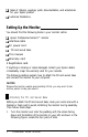
Ll Sales of ribbons, supplies, parts, documentation, and accessories for your Epson product tl Customer Relations. Setting Up the Monitor You should find the following items in your monitor carton: Cl Epson Professional Series 17” monitor U Interface cable Cl AC power cord CJ Tilt and swivel base Cl This manual 0 Warranty card 3 Registration card. If anything is missing or looks damaged, contact your Epson dealer immediately. Keep the warranty card for your records.
2. Make sure the upper sliding portion of the tilt and swivel base is flat and parallel to the bottom portion of the base, as shown below. Notice the four pairs of hooks and the locking tab on the top of the base.
3. 4 Position the base next to the bottom of the monitor and fit the hooks into the slots on the monitor.
4. As shown below, press the top comers of the base toward the monitor. The base slides downward as you press the corners. Then press the locking tab on the base toward the monitor’s connectors until it snaps into place. (This may require some force.) locked position Leave the monitor lying on its screen until after you follow the instructions in the next section.
If your computer or video adapter card does not have a VGA connector, you cannot use the interface cable that comes with the monitor. Determine the sync requirements of your video display controller and see the signal connector table on page 18 to determine which interface cable(s) you need. (See your dealer if you need help.) Then connect the appropriate interface cable(s) to the connector(s) on the monitor and computer. Perform only the appropriate steps below.
2. First connect the red cable to the monitor connector labeled R. To do this, align the cutouts in the rotating metal barrel of the cable connector with the tabs on the monitor connector. tabs 3. Fitting the cable connector’s barrel over the monitor connector, insert the cable connector into the monitor connector. Then turn the cable connector’s barrel clockwise as far as possible.
4. Use the same method to connect the green cable to the G/S connector, the blue cable to the B connector, the white cable to the H/C connector, and the black cable to the V connector. 5. Plug the monitor’s power cord into the power socket on the monitor. CAUTION Epson computers can support the weight of the monitor. If you plan to place your monitor on top of another type of computer, first verify that the computer can support the monitor’s weight (50 lbs). 6.
8. Plug the monitor’s power cord into a grounded electrical outlet. 9. You may need to change your computer’s DIP switch or setup program setting(s) to match the monitor. If you are using a video adapter card, you may need to set one or more DIP switches or jumpers on the card. See your computer or video adapter card users manual. Turning On the Monitor Follow these steps to turn on your monitor and computer: 1. Turn on your computer. 2.
The Control Panel This section describes the use of the control panel, shown below.
1 Adjusting the Brightness and Contrast To make the image on the screen clear and easy-to-read, use the brightness and contrast controls. Press the control to make it pop up and then turn it to adjust the brightness or contrast. When the setting is correct, you can press the control again to lock it in place. (Locking the control in place prevents it from being turned accidentally.) I The Operate Position To use the monitor, make sure the selector switch is in the operate position.
The monitor automatically selects which display mode to use. Its microcontroller analyzes the signal input (horizontal and vertical sync pulses) from the computer, checks the seven factory-set modes and any user-defined modes (up to seven), and uses the most appropriate mode in its memory. The signal input depends on your computer and application software. This section explains how to modify and recall factory-set display modes and create user-defined display modes.
Icon Display setting name Function Pin cushion/ barrel Straightens the vertical image edges. Use the increment button to increase the convex flex and the decrement button to increase the concave flex. Trapezoid (keystoning) Adjusts the slope of the vertical image edges. Use the increment button to decrease the width of the top edge and increase the width of the bottom edge. Use the decrement button to increase the width of the top edge and decrease the width of the bottom edge.
3. Use the increment and decrement buttons to adjust the image as described in the table above. Note For small changes, press the increment or decrement button once. To make a setting change continuously, hold down the increment or decrement button. 4. Repeat steps 2 and 3 for any other display settings you want to change. 5. When you are satisfied with the image you see, save the modified display setting(s) by turning the selector switch counterclockwise to the operate position.
1 Creating a User-defined Display Mode If you see dramatically misaligned images when you use a particular application program, you probably need to create a user-defined display mode. Follow these steps to create and store a user-defined display mode: 1. Display an image you want to align. 2. Follow steps 2 through 4 under “Modifying a Factory-set Display Mode” on page 12. 3. To save your display settings and create a new display mode, turn the selector switch counterclockwise to the operate position.
The power indicator is on, but there is no image on the screen. 1. Make sure the computer is turned on. 2. Make sure the interface cable is properly connected to the monitor and the video interface on the computer. (See “Connecting the Monitor to Your Computer” on page 5.) 3. Adjust the contrast and brightness controls. (See page 11.) 4. Make sure your computer’s DIP switch and setup program settings match the monitor.
Specifications CRT Size 17 inches (diagonal), flat square Dot pitch 0.26 mm Phosphor persistence Medium short Transmission Approximately 50% Deflection angle 90” Anti-glare treatment Silica coating Display Image size 11.8 inches x 8.7 inches f .12 inches (300mm x 225mmf3mm) Aspect ratio 4:3 Interfacing Requirements Input signal Analog video and TTL sync Video input 0 to 0.
Signal connectors BNC connectors Five BNC connectors: R, G/S, B, H/C, and V (red, green/sync, blue, horizontal/combined, and vertical) Separate horizontal and vertical sync R Composite sync Sync on green Red Red G/S Green Green Green (sync) B Blue Blue Blue H/C Horizontal Vertical/horizontal N/A V Vertical N/A N/A Interface cable computer connector 15-pin, D-sub, male connector Pin Signal Pin Signal 1 Red 9 Not connected 2 Green 10 Digital ground 3 Blue 11 Digital gr
Sync Signal Polarity I Mode H VGA 640 dots x 350 lines t VGA 640 dots x 400 lines VGA 640 dots x 480 lines I V I t VGA 1056 dots x 400 lines (132 column) - t Super VGA 800 dots x 600 lines - - t t 1024 x 768 interlaced (8514/A) I t 1024 x 768 non-interlaced I I I AC Line Voltage 90 to 132 and 180 to 264 VAC; 48 to 63 Hz Automatic line voltage selection Input Power 135 watts maximum I I Environmental Requirements Condition Operating range Non-operating range Temperature 40”
Dimensions Width 16.4 inches (411 mm) Height 15.5 inches (388 mm) Depth 17.4 inches (435 mm) Weight 50 lbs (22.
I Epson America, Inc. 20770 Madrona Ave.