MX-82 EPSON DOT MATRIX PRINTER Operation Manual MX MX-82 F/T EPSON P8190027-2
Copyright 0 1981 by EPSON, Shinshu Seiki Co., Ltd. Nagano, Japan “All rights reserved” *The contents of this manual are subject to change without notice.
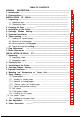
TABLE OF CONTENTS GENERAL DESCRIPTION.................................................................................... 1 1. Introduction ....................................................................................... 1 2 2. Characteristics................................................................................................ INSTALLATION OF MX-82................................................................................. 3 3 1. Unpacking..............................................
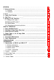
36 OPERATION . . . . . . . . . . . . . . . . . . . . . . . . . . . . . . . . . . . . . . . . . . . . . . . . . . . . . . . . . . . . . . . . . . . . 36 1. Switches and Indicators . . . . . . . . . . . . . . . . . . . . . . . . . . . . . . . . . . . . . . . . . . . . . . . . . . . . . . . . . . . . . . . . 1.1 Switches .................................................................................................. 36 1.2 Indicators ...........................................................................
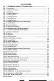
LIST OF FIGURES Fig. 1 EPSON MX-82 and MX-82 F/T Dot Matrix Printer.................................................. 1 4 Fig. 2 Contents of Carton . . . . . . . . . . . . . . . . . . . . . . . . . . . . . . . . . . . . . . . . . . . . . . . . . . . . . . . . . . . . . . . . . . . . . . . . . . . . . . . . . . 5 Fig. 3 Laying Printer on Firm Surface . . . . . . . . . . . . . . . . . . . . . . . . . . . . . . . . . . . . . . . . . . . . . . . . . . . . . . . . . . . . . . . . Fig. 4 Assembly Tools . . . . .
Fig. 44 Setting of Cut Paper Sheet.. .................................................................... Fig. 45 Printer with Cut Paper Sheet Set Completely.. ........................................ Fig. 46 Gap Adjustment....................................................................................... Fig. 47 Switches and Indicators on Control Panel ............................................... Fig. 48 Printer Initial Check ..........................................................................
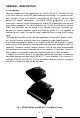
GENERAL DESCRIPTION 1. Introduction Ideal for computer business applications, the MX-82, MX-82 F/T Dot Matrix Printer is the latest extension of EPSON advanced printer technology. This new printer couples innovative design and precision manufacturing with long life, low cost, light weight and superior performance. The MX-82, MX-82 F/T features a 9 x 9 dot matrix print head that can be replaced easily, and 80 CPS bidirectional printing with logic seeking capability.
2. Characteristics The MX-82 and MX-82 F/T have been designed as a printer with versatile functions to meet a wide range of applications from small business to home uses and even for hobbies. The following is a brief summary of their major characteristics. (1) Plotter print Horizontal dot space is equal to the vertical dot space. Similar figure in propotion to that of CRT screen could be printed out onto the paper.
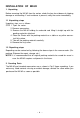
INSTALLATION OF MX-82 1. Unpacking Before removing the MX-82 from the carton, check the box for evidence of shipping damage or mishandling. If such evidence is present, notify the carrier immediately. 1.1 Unpacking steps Unpacking steps are as follows: STEP 1. Open the carton. 2. Remove accessories. 3. Remove the MX-82 holding its underside and lifting it straight up with the packing materials attached. 4. Place the Printer with the packing material on a table or any other convenient flat surface. 5.
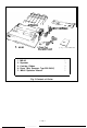
L 2. Separato 3. Cartridge Ribbon- * 1. MizizGkL (European Type) 1. 2. 3. 4. 5. MX-82 Separator Cartridge Ribbon Power (Only European Type 220/240V) MX-82 Operation Manual Fig.
3. Installation of the Printer (1) Operating site selection When installing the MX-82, observe the following instructions. (a) Place the Printer on a bench, tabletop or any other convenient flat surface with enough room for the separator in the back of the Printer. Your layout may look like Fig. 3. NOTE: Rubber feet are provided to prevent the marring of the surface where the MX-82 is placed.
(2) Removal of protective paper for paper end detector The MX-82 is provided with a protective paper inserted between the inner and outer paper guides to protect the paper end detector from damage due to shocks or vibrations during transportation. Before using the Printer, be sure to remove this paper. If the MX-82 is to be reshipped, remember to return it to the original position. (3) Prepare tools Prepare the following two screwdrivers to disassemble or assemble the printer.
0 If the printer lid is an obstacle when removing the shipping screws, be sure to take off the printer lid by observing the following steps. Rough or careless handling of the printer lid may result in damage to, or even breakage of, its hinges. STEP 1. Stand the printer lid upright. 2. Push the printer lid toward the right and pull up its left side. (See Fig. 6) Fig. 6 Removal of Printer Lid 0 When remounting the printer lid, be sure to observe the following steps: STEP 1.
4. Cartridge Ribbon Setting EPSON’s Cartridge Ribbon is compact, long-lasting, and very easy to set and remove. Furthermore, you have no need to soil your fingers in handling it. STEP 1. Open the printer lid (or remove it). 2. Confirm that the scale (paper retainer) is turned toward the platen and is touching it. 3. Push the cartridge ribbon down and set it on the printer mechanism.
Fig. 9 Cartridge Ribbon Setting NOTES 1: Incorrect setting of the ribbon may cause it to come off. 2: Confirm that the ribbon is neither twisted nor creased and that the cartridge is set properly. I Ribbon kRibbon Mask Incorrect Correct Incorrect Fig.
5. Separator Installation The separator of the Printer contributes to smooth paper feeding. Set the separator by inserting its edge into the two holes located at the rear part of the frame of the printer mechanism. (See Fig. 11) Paper Fig. 11 Separator installation 6. Paper Loading 6.1. Loading of fanfold paper The MX-82 Printer accommodates fanfold paper from 4” to 10” in width. To load the fanfold paper, observe the following procedure. STEP 1. Raise the printer lid. 2.
‘z&r Guiwaper Holding Cover IN OUT Fig. 12 Insertion of Fanfold Paper 5. Push the paper into the insertion slot between the paper guides at the rear part of the printer mechanism. NOTE: Be sure to pass the paper beneath the upper paper guide. 6. After the leading edge of the paper has emerged from the Printer, pull it out gently to some length.
7. Raise the two sprocket lock levers to loosen, and adjust the sprocket pin position to the paper width. (See Fig. 13) Paper Fig. 13 Raising of Sprocket Lock Levers 8. Engage the paper feed holes of the paper on the feeding pins, push the scale back into position, and adjust the tension of the paper. Then push the paper holding covers and the two sprocket lock levers down. (See Fig. 14) NOTE: In this case, confirm that the feeding pins are centered in the respective paper feed holes of the paper. Fig.
9. Put the printer lid on the Printer. Fig. 15 Printer with Fanfold Paper Set Completely NOTE: When the MX-82 is to be used on a desk or a bench, arrangement of the fanfold paper in parallel with the MX-82 as shown below will permit the paper to be folded in an accordion style. I I-_ Fig.
6.2 Removal of fanfold paper To remove the fanfold paper, follow either of the two methods described below. (1) To disengage the paper from the paper holding mechanism, pull it forward out of the Printer. NOTE: Do not attempt to pull out the paper in the backward direction. (2) Feed the paper out of the printer by electrical operation. For this, turn the Power Switch on and push the Line Feed button. (Details are described later.) 6.
Fig. 17 Top of Form 7. Gap Adjustment The adjustment of a gap between the head nose and the platen is used to adjust the printing pressure as well as to suit the paper of the different thickness. (1) Move the head adjusting lever (located on the left frame of the Printer) forward or backward to adjust the gap between the head nose and the platen. (See Fig. 18) Forward: To widen the gap. Backward: To narrow the gap. NOTE: With a thick paper, be sure to widen this gap.
8. Power Connection The EPSON MX-82 Dot Matrix Printer is capable of operating on the following three types of AC power. (1) 115V AC, 60 Hz (2) 220V AC, 50 Hz (3) 240V AC, 50 Hz Before connecting the MX-82 to a power source, make certain of the primary AC rating from the label located on the chassis at the rear of the Printer.
INSTALLATION OF MX-82 F/T 1. Unpacking Before removing the MX-82 F/T from the carton, check the box for evidence of shipping damage or mishandling. If such evidence is present, notify the carrier immediately. 1.1 Unpacking steps Unpacking steps are as follows: STEP 1. Open the carton. 2. Remove accessories. 3. Remove the MX-82 F/T by holding its underside and lifting it straight up with the packing materials attached. 4.
2. Counting the Parts The MX-82 F/T and standard accessories are as shown in Fig. 19. Upon unpacking, if you notice any listed contents missing or evident damage, contact the store where you purchased the MX-82 F/T as soon as possible. Dot Matrix Printer (European Type) 1. 2. 3. 4. 5. MX-82 F/T Separator Cartridge Ribbon Power Cord (Only European Type 220/240V) MX-82 F/T Operation Manual Fig. 19 Contents of Carton - 1 8 - 5.
3. Installation of the Printer (1) Operating site selection When installing the MX-82 F/T, observe the following instructions. (a) Place the Printer on a bench, tabletop or any other convenient flat surface with enough room for the separator in the back of the Printer. Your layout may look like Fig. 20. NOTE: Rubber feet are provided to prevent the marring of the surface where the MX-82 F/T is placed.
(2) Removal of protective paper for paper end detector The MX-82 F/T is provided with a protective paper inserted between the inner and outer paper guides to protect the paper end detector from damage due to shocks or vibrations during transportation. Before using the Printer, be sure to remove this paper. If the MX-82 F/T is to be reshipped, remember to return it to the original position. (3) Prepare tools Prepare the following two screwdrivers to disassemble or assemble the printer.
0 If the printer lid is an obstacle when removing the shipping screws, be sure to take off the printer lid by observing the following steps. Rough or careless handling of the printer lid may result in damage to, or even breakage of its hinges. STEP1. Stand the printer lid upright. 2. Push the printer lid toward the right and pull up its left side. (See Figs. 23 (1) and (2)) Printer Lid (1) Standard (2) Option Fig. 23 Removal of Printer Lid NOTE: The printer lid shown in Fig.
4. Cartridge Ribbon Setting EPSON’s Catridge Ribbon is compact, long-lasting, and very easy to set and remove. Furthermore, you have no need to soil your fingers in handling it. STEP 1. Open the printer lid (or remove it). 2. Confirm that the scale (paper retainer) is turned toward the platen and is touching it. 3. Push the cartridge ribbon down and set it on the printer mechanism.
NOTES: 1. Incorrect setting of the ribbon may cause it to come off. (See Fig. 26) 2. Confirm that the ribbon is neither twisted nor creased and that the cartridge is set properly. .-Ribbon I Incorrect Ribbon Mask Correct Incorrect Fig. 26 Examples of Correct and Incorrect Ribbon Setting 5. Separator Installation The separator of the Printer contributes to smooth paper feeding. Set the separator by inserting its edge into the two holes located at the rear part of the frame of the printer mechanism.
6. Mounting and Dismounting of Tractor Unit The tractor unit of the MX-82 F/T is detachable. If it is an obstacle when using roll paper, it can be taken out as follows; STEP 1. Release the lock levers of the tractor unit by pulling in the direction as shown in Fig. 28. 2. Keep pulling the levers and pull up the tractor unit. Lock Lever Fig. 28 Dismounting of Tractor Unit To install the tractor unit, hook the notches of the tractor frames onto the shaft shown in Fig.
7. Paper Loading 7.1 Fanfold paper 7.1.1 Loading of fanfold paper The MX-82 F/T Printer accommodates fanfold paper from 4” to 10” in width. To load the fanfold paper, observe the following procedure. STEP 1. Raise the printer lid. 2. Unlock the release lever by pulling it in the direction of the arrow. (See Fig. 30) 3. Pull the scale toward the front of the Printer to detach the scale from the platen. 4. Confirm that the paper guide roller is at the center of the sprocket shaft.
8. Raise the two sprocket lock levers to loosen, and adjust the sprocket pin position to the paper width. (See Fig. 31) ket Lock Lever I Fig. 31 Raising of Sprocket Lock Levers 9. Engage the paper feed holes of the paper on the feeding pins, push the scale back into position, and adjust the tension of the paper. Then push the paper holding covers and the two sprocket lock levers down. (See Fig.
10. Put the printer lid on the Printer. (See Fig. 33) Fig. 33 Printer with Fanfold Paper Set Completely NOTE: When the MX-82 F/T is to be used on a desk or a bench, arrangement of the fanfold paper in parallel with the MX-82 F/T as shown below will permit the paper to be folded in an accordion style. Fig. 34 Example of Paper Arrangement 7.1.2 Removal of fanfold paper To remove the fanfold paper, follow either of the two methods described below.
7.1.3 Column layout on fanfold paper When fanfold paper of from 4” to 10” in width is supplied with the MX-82 F/T, the graduations on the scale can be used as the indexes of print column positions (I to 96). Alignment of the print start position on fanfold paper with the 1st column position at the extreme left of the scale will facilitate column layout. Accordingly, center the paper by adjusting it to these indexes of the scale. 7.1.
7.2 Roll paper 7.2.1 Roll paper holder EPSON offers the roll paper holder as an optional accessory for the MX-82 F/T. 7.2.2 Loading of roll paper The MX-82 F/T accomodates a roll of single play paper measuring 8.5 kO.12 in. in width with a 1 in. core. To load it, observe the following procedure. STEP 1, Raise the printer lid. 2. Unlock the release lever by pulling it in the direction of the arrow. (See Fig. 36) 3. Pull the scale toward the front of the Printer to detach the scale platen. (See Fig. 36) 4.
r Fig. 37 Loading of Roll Paper (2) Release Lever Manual Paper Feed Knob Fig. 38 Loading of Roll Paper (3) 7.3 Cut paper sheet 7.3.1 Loading of cut paper sheet The MX-82 F/T accommodates cut paper sheets measuring 8.3” to 8.5” in width. To load a cut paper sheet, observe the following procedure. STEP 1. Raise the printer lid. 2. Unlock the release lever. (See Fig. 39) 3. Pull the scale toward the front of the Printer to detach the scale from the platen. (See Fig. 39) 4.
Release Lever Fig. 39 Loading of Cut Paper Sheet 6. Lock the release lever. 7. While turning the manual paper feed knob clockwise, confirm that the paper advances straight up. (See Fig. 40) Manual Paper Feed Knob Fig. 40 Adjustment of Inserted Paper Position If not, adjust the inserted paper position as follows: a) If the cut paper sheet or form is long enough, unlock the release lever and align the side edges of the paper as shown in Fig. 41.
Fig. 41 Alignment of Side Edges b) If the cut paper sheet or form is not long enough to align the side edges, align the top edge of the paper with the form position setting mark on the tractor unit. (See Fig. 42) Fig. 42 Form Position Setting Mark The print area on the cut paper sheet is shown in Fig. 43. 210 mm (8.3”)-218 mm f8.5”) m5-8 5-8 mm 1 28.6 30.2 305 ! or mm, :c”sE”~. CDE 012 123 234 mm (’ 2”]J7:q Fig.
Letter Size Paper I+--..- A4 Size Paper t-y1. Fig. 44 Setting of Cut Paper Sheet NOTES: 1. The Paper End Detector function may be disabled under software control (ESC 8; refer to page 66 provided printing is left off within 7.5 mm from the paper bottom edge). 2. If the paper is set on the line marked 1/4 as shown in Fig. 44, then the printing starts from a position 28.6 mm below the top edge of the paper. If the paper is set on the line marked 1/8, then the printing starts from a position 30.
8. Gap Adjustment The adjustment of a gap between the head nose and the platen is used to adjust the printing pressure as well as to suit paper of a different thickness. (1) Move the head adjusting lever (located on the left frame of the Printer) forward or backward to adjust the gap between the head nose and the platen. (See Fig. 46) Forward: To widen gap. Backward: To narrow gap. NOTE: With a thick paper, be sure to widen this gap.
Head Adjusting Le BBackward M Forward @I Head Adjusting Lever (Side view) Fig.
OPERATION 1. Switches and Indicators There are three switches and four indicators (green LED’s) on the control panel and one power switch on the right side of the Printer case. In this section, panel operating procedures are covered in sufficient detail for the user to become familiarized with the Printer. (See Fig. 47 for the control panel.) I Control Panel Fig. 47 Switches and Indicators on Control Panel 1.1 Switches POWER SW: ON LINE SW: Controls primary AC power to the Printer.
FF SW: (Form Feed) When this switch is depressed once, the paper is advanced vertically to the next Top of Form position. This switch must be depressed while the Printer is OFF-LINE. Otherwise, the form feed operation will not be carried out. The Top of Form position is initialized when the POWER switch is turned on or when INIT signal is applied to the interface connector. Therefore, before turning the POWER switch on to start operating the Printer, set the paper at the appropriate Top of Form position.
1.3 Printer initial check Take the following steps and become familiar with the Printer. 7 START Interface cable Turn on POWER Check the LF & FF Contact your nearest EPSON dea,er. qg&&x+ Fig.
2. Buzzer The buzzer is located inside the Printer case, and sounds for about one second when the Printer receives BEL code ((07)20H). (See page 66 for the BEL code.) 3. Paper End Detector (1) When the paper end detector (a reed switch located on the paper guide) detects that the paper is nearly exhausted, the signals on the interface connector change to the following status, and the printing operation stops.
(2) When the Printer falls into paper-out status, it is automatically put in the OFF-line state and paper advancement can be performed by depressing the LF switch. After setting new paper in the Printer, depress the ON-LINE switch so that the Printer may resume operation. (3) There is another way to start the Printer again when it falls into paperout status. Set new paper in the Printer, and turn the POWER switch off and on again, or apply the INIT signal.
b) Turn the DIP switch 2-3 (on the control circuit board) ON to effect auto-line feed. c) Set the adequate ASCII code data to be printed. To obtain low logic level signals, connect the data transfer line required for printing (pin Nos. 2 to 9) to GND level (pin No. 33, etc.) * Example of printing “Z” “Z”-[5,A]H-(0101 1010) In this case, connect pin Nos. 2, 4, 7 and 9 to pin No. 33. 5.
Turn the printer upside down on a soft surface. With a Phillips type screwdriver, completely loosen all 4 screws. (See Fig. 51) Place tape over the 4 holes so the screws won’t fall off when you tip the printer right side up. Fig. 51 Loosening All 4 Screws Tip the printer right side up again. Gently loosen the upper case. Lift up the cover from the left side. And then pull out the wires hooked to the control panel on the right. (See Fig. 52) Upper case Lead wire Fig.
See the inside of the printer before you set the switches. The printer consists of a printer mechanism, a controller, a transformer and filter circuit board, and a control panel. (See Fig. 53) Construction of the Printer Transformer & Control panel I I Transformer & filter circuit board ter mechanism MX-82 or MX-82 F/T Dot Matrix Printer Driver circuit board 7i(cd 1 female) HMTP board (Control circuit board) J / Controller Fig.
DIP swit$h 2 VIP switch 1 Fig. 54 Location of DIP Switches -I Position the printer as shown in Fig. 53. There are two “DIP’ (DUAL IN-LINE PACKAGE) switches in the HMTP board. (See Fig. 54) The switches set to the left are ON... to the right are OFF. (See Fig. 55) SW 1 Fig. 55 Setting DIP Switches Each switch No. of the DIP switch functions as described below. So set these switches to suit your application or the computer’s specifications.
5.1 Setting of DIP Switch No. 1 The DIP switch No. 1 consists of the following 8 pins. A summary of the functions of the respective DIP switch pins and their preset conditions at the time of shipment are shown in Table 2. Table 2 Functions and Conditions of DIP Switch No. 1 (1) SW1-1: Setting this pin to the ON position will cause the line spacing to be automatically set at 1/8 inch per line upon power application.
(8) Character sizes and maximum column lengths can be specified as follows: Table 3 Character Size and Maximum Column Length ~~ If you turn any of the above character sizes to the enlarged character print mode, then the maximum column length will be reduce to half of them. 5.2 Setting of DIP Switch No. 2 The DIP switch No. 2 consists of the following 4 pins. A summary of the functions of the respective DIP switch pins and their preset conditions at the time of shipment are shown in Table 4.
5.3 Coding Tables Appendix 4 shows all available codes when the Printer is set for operation with standard coding by setting the DIP switch pins 1-7, 2-1 and 2-2 to all ON position, Table 5 shows International Character Set Designation according to the combination of the DIP switch setting. Table 5 International Character Set Designation The above settings can be changed to any country character sets by inputting ESC R + n control codes.
5.4 Setting Sequence of Functional Specifications The MX-82, MX-82 F/T have a choice of various functional specifications such as amount of line spacing, form length per page, number of columns per line, automatic skip-over perforation. etc. for selection under the control of both hardware (DIP switches) and software (control codes) which is described later. In Figs. 56 through 59, setting sequence of these functional specifications are illustrated. 1/8 inch ESC0 c 4 ESC0 0 118 inch Fig.
YES 12 inch ESCCtn ESCC+O+m The skip-over perforation function, if previously set, will be reset at this point. Fig.
(7 Power ON 96 columns Normal Emphasized SI or - ESCSI 4 print print 0 DC2 I Fig.
l-inch skip-over perforation function not provided YES NO l-inch skip-over perforation function provided i-1 ESCN+n ESC 0 t Fig.
This chapter describes the MX-82, MX-82 F/T (hereinafter refered to as MX-82) from the viewpoint of hardware and software. The contents of the chapter are; 1. What is a dot matrix printer? 2. Definitions of some terms often used. 3. Control codes in the text mode 4. Control codes in the bit image mode 5. Print samples in the both modes This printer has two different print modes. One is the text mode, another is the bit image mode. You might be familiar with the text mode because an ordinary printer has it.
The dot matrix printing method allows a printer to easily form any desired character, It has a print head that contains 9 needles vertically and can create distinctive characters like with typewriter. In that sense it is one of the key features that the printer has. EPSON’s MX-82 can control each needle programmably, expanding the ability of the printer. See next how the print head works and forms a character. (1) Dot Matrix Printer The print head contains 9 “needles” or “wires” vertically.
This is called “Dot Matrix Printing”. Dots are printed according to a pre-designed “Matrix” or “Grid” system, where each letter, number and punctuation mark is formed by arrangement of dots. In the above figure, the print head moves from left to right.
2. Definitions of Some Terms Often Used Before looking at the printer in detail, some terms should be defined first so that you can understand them more easily and in less time. They are; * ASCII code * Escape codes * “+” symbol * 2, D and H If you are already familiar with the above terms, skip these paragraphs. (1) ASCII code Characters in computer systems are represented by groups of bits.
The “ESCAPE” codes used in the MX-82 should not be confused with the escape key which some computers have. So be familiar with EPSON’S control codes. (3) “+” symbol You will see “+” symbol often in the explanation or description of control codes from now on. This symbol is used for legibility only and may not be input in your actual program. (4) 2, D (or Dec.) and H (or Hex.) ( )z, ( )D and < >H respectively represent binary, decimal and hexadecimal numbers. 3.
(3) Character designation codes SO, ESC SO, DC 4... Enlarged printing SI, ESC SI, DC 2... Condensed printing ESC E, ESC F... Emphasized printing ESC R... International character set (4) Other codes DC 1, DC 3... Selection or deselection of the printer ESC 8, ESC 9... Selection or deselection of the paper end detector BEL... Bell BS... Back space NUL... Nul ESC K, ESC L... Access code to Bit Image mode (described later). 3.
(3) VT (Vertical Tabulation) When the VT code is input, all data preceding this code is printed and the vertical tabulation is made to a predetermined line position set by “ESC B” (up to 8 positions). If no vertical tab position is set by ESC B, the VT code behaves like the LF code. Therefore, the paper is advanced one line after printing.
r 1. In case of 5th. 10th and 219 columns. [DATA] -1 <5>H H <15>Hm ABC m DEF lHTj GHl bg JKL a (LFI [PRINT] 2. AEC DEF JKL GHI In case of lack of stop position. [DATAI -1 <5>H H m ABC m DEF m GHI m JKL @Ja [PRINT] 3. ABC DEF GHI JKL In case of character data transferring over next tab stop. [DATA] -1 <5>H H <15>H m ABCDEF m GHI m JKL /EiiJpJ [PRINT] 4. GHI AECDEF J KL. In case of transferring two HT codes at a time.
(4) ESC A + n (for setting amount of line spacing) This code specifies the amount of line spacing in the Line Feed, provided that (n)o must satisfy the condition: 1 s (n)b Z 85 (Decimal). “n” - 1 is equivalent to 1/72 inch paper advancement. Since the distance between any two dot wires of the print head is 1/72 inch, any line spacing in increments proportional to the distance between the dot wires can be established. NOTES: 1. When the POWER switch is turned on or INIT signal is applied to the pin No.
(5) ESC 0 input of the ESC 0 causes the subsequent line spacing to be set at 1/8 inch. (6) ESC2 Input of the ESC 2 causes the subsequent line spacing to be set at either 1/6 inch or 1/8 inch depending on the initial set condition of the DIP switch pin 1-1. (7) VT (Vertical Tabulation) See paragraph 3.1 (3) above. (8) ESC B + nc + n2 + + nk + NUL ( 1 5 k5 8,nks nk+l) This code specifies the vertical tab stop positions.
(9) FF (Form Feed) See paragraph 3.1 (4) above. (10) ESC C + n (for setting a form length) ESC C + n (n + 0), ESC C + [O]H + m (for setting form length) The “ESC C + n” codes specifies the form length which is determined by the number of lines (n: 1 s (n)n $ 127 where the value of “n” is a positive number and must not exceed 127 lines). In other words, the maximum form length is 127 lines. The amount of line spacing when this code is input is a predetermined numerical value by ESC A+ n.
(Example) 3-line skip-over perforation [PRINT] BQBBc~!:4BQ BBBQ(1!BBQ mx!Bc~!:Jm! (at 1/6 inch line spacing) Skip for 3 lines End of previous page Top of form position Beginning of next page (12) ESC 0 This code cancels the skip-over perforation set by the ESC N + n code. 3.3 Character designation codes (1) SO (Shift Out) (for enlarged characters) When the SO code is input, all data that follows it in the same line will be printed out in enlarged (double width) characters.
(2) SI (Shift In) (for condensed characters) When the SI code is input, all data that follows it will be printed out in condensed characters. This code is cancelled by the input of “DC 2” code. The SI code can be input at any column position on a line, but all characters/symbols on the line containing SI code are printed out in condensed characters. Normal and condensed characters cannot be mixed on the same line.
(7) ESC E (for emphasized characters) The ESC E code causes the Printer to print emphasized characters. Emphasized printing gives the character stronger impression on the paper. This code can be input in any column position on a line, but all characters on the line containing ESC E code are printed out in emphasized characters. The speed of the head carriage reduces to 40 CPS while printing emphasized characters. 1. [DATAI LPR -E] ABCDEFGHI ICR] ILF] INTI CIBCDEFGHI 2.
3.4 Other codes (1) DC 1 (Device Control 1) The DC 1 code places the Printer in the Selected state. It enables the Printer to receive data. With the Printer in the Selected state, if the DC 1 code is input during data transfer, all data stored before the DC 1 code is ignored. (2) DC 3 (Device Control 3) The DC 3 code places the Printer in the Deselected state. In other words, it disables the Printer to receive data.
(6) BS (Back Space) The BS code cancels the data immediately preceding this code in the Text Mode. In other words, one byte data stored prior to the BS code is cleared from the print buffer, as though that data has not been transferred from the host computer. Note that this code is valid only in the Text Mode. (7) NUL (Null) The NUL code is regarded as the termination for tabulation setting sequence. The lack of the NUL code would cause incorrect data printout.
4.1 Normal-density bit image mode setting by ESC K + nl + nz To convert the printer’s operation mode from Text to Normal-density Bit Image, the “ESC K + nl + nz” code must be input. (Here, the sign “+” is inserted for the purpose of legibility only and should not be input in actual operation.) Namely, when ESC (< 1 B> H and K (< 4B> H) codes and data ni and nz are input, the Printer recognizes the data following the “ESC K” as the bit image data.
Printing Text data A Bit-image data B Bit-image data D Text data C 576 bit-image positions (Ex. 3) Input data nz. t ni I Printing (Ex. 4) Bit image data transfer by standard BASIC program To check for proper coversion to the Normal-density Bit Image mode, execute the following program.
4.2 Dual-density bit imagemode setting by ESC L + nl + nz When the ESC (< 1 B> H) and L (< 4C > H) codes followed by data nc and n2 are input, the printer’s operation mode is converted from Text to Dual-density Bit Image. The transfer sequence of bit image data is the same as with the ESC K (normal-density bit image printing), but bit image printing can be performed in twice the dot density in the horizontal direction as with the ESC K.
4.3 Relationship between data and dot wires Fig. 63 shows the relationship between the Bit Image data and the dot wires in the print head. You can control arbitrary 8 dot wires in the print head. LSB Input data Dot wire NOTE: In the Bit Image mode, the 9th dot wire cannot be used. l 04 l 0 .l 0 & Fin. 63 Relationship between Data and Dot Wires If a bit is “1“, the print head fires. If a bit is “0”, the print head does not fire.
4.4 How to obtain nl and n2 In the MX-82 Printer, you have to send the amount of data by nr + n2 in hexadecimal numbers following the ESC K or ESC L. If the amount of bit image data is 300, then nt and nz may be derived as follows; nl = (Amount of data) MOD 256 = 300 MOD 256 = <44>D = <2c>H n2 = INT (Amount of data/256) = INT (300/256) =D -H You can also use Appendix 4, code Table, to find the corresponding hexadecimal numbers to the decimal numbers.
4.5 Programming examples (1) Dual-density bit image printing Fig. 65 Example of Graphic Pattern Formation NOTE: The most significant bit (MSB) of the bit image data corresponds to the dot wire at the uppermost position. For example, to print a graphic data as shown in Fig. 65, a program such as shown below must be executed. However, this program has been developed using standard BASIC language. If extended BASIC is to be used, the program must be changed according to the features of the language.
(3) Difference between ESC K and ESC L The normal-density mode is accessed with ESC K. The dual-density mode is accessed with ESC L MSB -0 - Direction of print head movement I 0 LSB -0 The print head fires space / between normal dot positions (Print speed reduces to - half the speed in normaldensity printing.) a) Normal density b) Dual density Fig. 66 Normal-Density and Dual-Density Modes NOTE: Print alignment under the friction feed.
(4) Example of CRT screen dump hard copy This print example is made using APPLE II® computer and the demonstration diskette. Fig.
(5) Example of expression of brightness using the Bit Image Mode (Ex.) Expression of brightness using the bit image mode 4 5 6 (Ex.) Expression of dot density A: a.... @*.*a @em*. l oe*a l ee*o me@.@ l oae* Data will be transmitted in order of (8-dot line spacing) H and then < 55 > H 0: Data will be transmitted in order of < FF> H and then (8-dot line spacing) c: Data will be transmitted in order of two H and then two <33>11. (8-dot line spacing) Fig.
MAINTENANCE 1. Preventive Maintenance Preventive maintenance for the MX-82 and MX-82 F/T consist basically of cleaning. The Printer should be cleaned with a soft brush to remove paper dust and particles after every three months of use. The exterior surface of the Printer can be cleaned by using a mild detergent and water solution. 2.
Print Head 1 Print Head Unit , Terminal Board Head Lock Lever Head Connector ‘Be sure to hold this connector firmly lo pull the head cable out straight Carnage Assembly (Side View) ‘Take hold of the cable at the point izicated b y ariows o and apply force in either of the directions indicated by arrow c) to push in or pull out the head cable. Fig.
SPECIFICATIONS (1) PRINT METHOD: (2) PRINT SPEED: (3) PRINT DIRECTION: Serial impact dot matrix 80 CPS Bidirectional with logic seeking Unidirectional in the bit image mode (4) NUMBER OF PINS IN HEAD: (5) LINE SPACING: 9 4.23 mm (1/6”) or 3.
SPECIFICATIONS (continued) (1 1) MCBF: 5 x 10⁶ lines (excluding print head) (12) ENVIRONMENTAL CONDITIONS Operating Temperature Range: 5 to 35’C (41 to 95’F) Operating Humidity: 10 to 80% non-condensing (13) POWER REQUIREMENT Voltage: 115V.60Hz 220/240V, 50 Hz Current: 1 Amp maximum Power Consumption: 100 VA maximum (14) PHYSICAL CHARACTERISTICS MX-82 MX-82F/T Height: 107 mm (4.2”) 133 mm (5.2”) 374 mm (14.7”) 374 mm (14.7”) Width: Depth: 305 mm (12.0”) 305 mm (12.0”) Weight: 5.5 kg (12 Ibs.) 7.0 kg (15.
APPENDIX 1 Construction of MX-82 and MX-82 F/T The EPSON MX-82 and MX-82 F/T dot matrix printers consist of the following three major functional blocks. (1) Printer Mechanism (2) Control Circuit Board (3) Power Circuit These three blocks are housed in a plastic case and are connected to one another. 1.1 Printer mechanism The printer mechanism has been developed by EPSON Shinshu Seiki Co., LTD., with the latest technology in the precision and electronic industry fields.
Fig.
1.3 Power circuit The power circuit generates 5V DC for the logic circuit, and 24V DC to energize the solenoids of the print head and two stepper motors. 1.4 Printer initialization Printer initialization is accomplished in either of the two ways described below. (1) initialization takes place automatically each time the primary AC power source is interrupted and reapplied (i.e., by turning the Power Switch off and on).
9 X 2SD986 - HI D H: - LFA LFA 0 LFC 0 - LFD Fig.
APPENDIX 2 Parallel Interface Both the MX-82 and MX-82 F/T include a parallel interface as the standard equipment, and this paragraph describes the parallel interface. (1) Specifications 1000 CPS (min.) (a) Data transfer rate: By externally supplied STROBE pulses. (b) Synchronization: By ACKNLG or BUSY signal. (c) Handshaking: Input data and all interface control signals are compa(d) Logic level: tible with the TTL level.
Table A2-1 (cont’d) ; 14 / - 15 16 - 17 16 - 19to30 - lmi In NC Not used. OV Logic GND level. %nosas- Printer chassis GND. In the printer, the chassis GND and the logic GND are isolated from each other. - NC GND Not used. E;fTED-PAIR RETURN signal GND - When the level of this signal becomes “LOW”, the printer controller is reset to its initial state and the print buffer is cleared.
3. All interface conditions are based on TTL level. Both the rise and fall times of each signal must be less than 0.2 p.s. 4. Data transfer must not be carried out by ignoring the ACKNLG or BUSY signal. (Data transfer to this printer can be carried out only after confirming the ACKNLG signal or when the level of the BUSY signal is “LOW’.) (4) Data transfer sequence Fig. A2-1 shows the sequence for data transmission. BUSY ACKNLG DATA STROBE Fig.
NOTES: 1. In Table A2-2, it is assumed that as soon as the Printer receives data, it sends back the ACKNLG signal, though this data is not stored in the print buffer. In this status, the Printer is waiting for the DC 1 code for normal entry. 2. In the above table, it is also assumed that no ERROR status exists other than that attributable to the OFF-LINE position of the ON-LINE switch. In the ERROR status, the Printer is not in the Selected state (SLCT “LOW”). 3.
I Hex. No. o , 2 3 4 I”S( I .
APPENDIX 4 Character Fonts (Hex Code ) 20 28 -21 23 24 25 26 ti i i iJ 29 28 2c 20 2E 38 3c 27 32 38 3E 42 48 60 49 4A 3F 46 48 4c 52 - 9 2 - 40 4E AF ,.
58 59 5A 50 5c 5D 69 69 6A 6B 6C 6D 5E liiiil 78 79 7A 73 .. 78 7c NOTE: Numbers represent Hex.
FRANCE 40 5B 5c 5D‘ 78 7c 7D 7E liiiil GERMANY 5B 5c 5D 5c 5D 78 70 7D - 7E 60 70 ENGLAND 23 DENMARK SWEDEN 24 ITALY 7c 7D 7E 58 5D 60 70 5c 5D 78 7c 7D 7E
SPAIN 23 55 5c 50 78 - 9 6 - 7c
APPENDIX 5 Control Codes Control code Hex. Dec. NUL 00 0 BEL BS HT 1 1 07 08 09 1 1 7 8 9 Function Ref. page F;LJL; Ends tab setting. Follows ESC B and 67 BELL. Sounds buzzer for about 1 seconds. 1 Back space. Cancels a last character input. 1 Horizontal Tabulation. 66 1 67 1 58 Device Control 2. Turns off the condensed Device Control 3. Deselects printer. Not ready to Device Control 4.
FEDERAL COMMUNICATIONS COMMISSION RADIO FREQUENCY INTERFERENCE STATEMENT “This equipment generates and uses radio frequency energy and if not installed and used properly. that is, in strict accordance with the manufacturer’s instructions, may cause interference to radio and television reception.
EPSON sl+NsHu SEKI CQLTR EPSON OVERSEAS MARKETING LOCATIONS EPSON AMERICA, INC. (LA) 3415 Kashiwa St. Torrance, Ca. 90505 Phone: (213)539-9140 Telex: 182412 EPSON DEUTSCHIAND GMBH Am Seestern 24 4000 Diisseldotf 11. F.R. Germany Phone: 0211-5961001 Telex: 8584786 EPSON U.K. LTD. Sherwood Howe 176 Northolt Road South Harrow HA2 OEB U.K. Phone: (01)422-5612 Telex: 8814169 (01)422-1118 PRINTED IN JAPAN 82.