EPSON ® POWERSPAN.
IMPORTANT NOTICE DISCLAIMER OF WARRANTY Epson America makes no representations or warranties, either express or implied, by or with respect to anything in this manual, and shall not be liable for any implied warranties ofmerchantability and fitness for a particular purpose or for any indirect, special, or consequential damages. Some states do not allow the exclusion of incidental or consequential damages, so this exclusion may not apply to you. COPYRIGHT NOTICE All rights reserved.
Important Safety Instructions Read all of these instructions and save them for later reference. Follow all warnings and instructions marked on the computer. . Unplug the computer before cleaning. Clean with a damp cloth only. Do not spill liquid on the computer. . Do not place the computer on an unstable surface or near a radiator or heat register. . Do not block or cover the openings in the computer’s cabinet. Do not insert objects through the slots. .
Importantes instructions de sécurité Lire attentivement les instructions suivantes et les conserver pour les consulter en cas de besoin. Observer soigneusement tous les avertissements et directives marques sur l’ordinateur. l l l l l l l l l Debrancher l’ordinateur avant de le nettoyer. N’utiliser qu’un chiffon humide. Veiller a ne pas renverser de liquides sur l’appareil. Ne pas placer l’ordinateur sur une surface instable ni pres dune source de chaleur.
Contents Introduction SCSI Subsystem ................. . . . . . . . . . . . . . . . . . . . . . . . . . . . . . . . .2 Software . . . . . . . . . . . . . . . . . . . . . . . . . . . . . . . . . . . . . . . . 3 Features of This Manual . . . . . . . . . . . . . . . . . . . . . . . . . . . . . . . . . . . . . 3 Where to Get Help . . . . . . . . . . . . . . . . . . . . . . . . . . . . . . . . . . . . 4 CompuServe On-line Support ........ . . . . . . . . . . . . . . . . . . . . . .
Configuring Your System . . . . . . . . . . . . . . Starting the Program . . . . . . . . . . . . . . Setting the Date and Time . . . . . . . . . . . . . . . Performing the Configuration Steps . Adding or Removing a Board . . . . . . . . . . . . . Defining the Configuration Settings . Hard Disk Drive Types . . . . . . . . . . . . . . . Using Advanced Configuration Options . Using Alternate Configuration Files . . . . . . . . Creating an Alternate SCI File . . . . . . . . . Loading an Alternate SCI File . . .
Installing the Video Drivers and Utilities. . . . . . . . . . . . . . . . . . . . . . . . Installing MS-DOS Video Drivers and Utilities . . . . . . . . . . . . . . . Installing Windows 3.1 Drivers . . . . . . . . . . . . . . . . . . . . . . . . Using the SCSI Subsystem . . . . . . . . . . . . . . . . . . . . . . . . Installing SCSI Terminators . . . . . . . . . . . . . . . . . . . . . . . . Installing SCSI Devices . . . . . . . . . . . . . . . . . . . . . . . . Configuring the SCSI Subsystem . . . . . . . .
Chapter 7 Installing and Removing Disk Drives Using the Correct Drive Bay . . . . . . . . . . . . . . . . . . . . . . . . . . . . . 7-2 Installing a Drive in an External Bay . . . . . . . . . . . . . . . . . . . . . . . . . . . . 7-3 Removing a Drive from an External Bay . . . . . . . . . . . . . . . . . . . . . . . . 7-8 Installing and Removing an IDE Hard Disk Drive . . . . . . . . . . . . . . . . . . . . 7-9 Removing the IDE Drive Bay Assembly . . . . . . . . . . . . . . . . . . . . . . .
Appendix B Specifications Main System Board . . . . . . . . . . . . . . . . . . . . . . . . . . . . . . . . . . . . . . . CPU Card . . . . . . . . . . . . . . . . . . . . . . . . . . . . . . . . . . . . . . . . . . . . . . . Interfaces . . . . . . . . . . . . . . . . . . . . . . . . . . . . . . . . . . . . . . . . . . . . . . . Controllers . . . . . . . . . . . . . . . . . . . . . . . . . . . . . . . . . . . . . . . . . . . . . . . Keyboard . . . . . . . . . . . . . . . . . . . . . . . . . . . . . . . . . .
Introduction The EPSON ® PowerSpan ® computer is a powerful, versatile system ideally suited for use as a network file server. It incorporates the latest EISA (Extended Industry Standard Architecture) technology and a built-in dual-SCSI (Small Computer System Interface) subsystem in a convenient tower design. Its exceptional features and flexibility enable you to use the most advanced peripheral devices and software while maintaining full compatibility with ISA technology.
SCSI-II subsystem consisting of two SCSI channels with interfaces built into the main system board IDE hard disk drive interface for two hard disk drives Diskette drive controller for two diskette drives Mass storage space for up to nine half-height drives: two internal bays for IDE hard disk drives or SCSI drives, four internal bays for SCSI drives, and three externally accessible bays for diskette, tape, or CD-ROM drives.
Included with your system is a System Configuration diskette containing the EISA Configuration utility and various EISA System Utilities. These programs allow you to configure your computer, SCSI subsystem, and EISA option cards, as well as customize many other system features.
Chapter 1 provides instructions for setting up your system. Chapter 2 describes how to run the SETUP program to configure your computer when you do not have a diskette drive or did not install any EISA option cards. Chapter 3 describes how to run the EISA Configuration utility to configure your computer when you have installed EISA option cards.
You can also contact the EPSON marketing location nearest you for customer support and service. International marketing locations are listed at the end of this manual. When you call for technical assistance, be ready to identify your system and its configuration, and provide any error messages to the support staff. See Appendix A for more information. If you need help with any software application program you are using, see the documentation that came with that program for technical support information.
Chapter 1 Setting Up Your System This chapter describes how to set up and start using your computer system for the first time. Before you set up your system, be sure to read the “Important Safety Instructions” at the beginning of this manual. Preparing to Set Up Your System It is important to choose a safe, convenient location for your system that provides the following: A flat, hard surface. Place the computer on an anti-static mat if the surface is carpeted. Good air circulation.
If the power cord supplied with your system is not compatible with the AC wall outlet in your region, obtain a suitable power cord that meets the following criteria: 0 The power cord must be rated for at least 125% of the current rating of the AC voltage system. For more information, see Appendix B. 0 The power cord connector that plugs into the wall outlet must be an appropriately grounded male plug. 0 The power cord connector that plugs into your system must be an IEC type CEE-22 female connector.
2. The keys for the front panel door lock are taped to the inside of the door. Open the door to remove the keys. (It might be a little hard to open the door the first time.) 3. Install any optional equipment you want to add to your computer, such as disk drives, memory modules, or EISA option cards. You may not want to install any ISA option cards yet (unless you will use an ISA card to control your monitor). See “Installing Optional Equipment,“ on page 1-5. 4.
Setting the Voltage Selector Switch Your system is powered by a 230 watt power supply. The power supply voltage is controlled by a voltage selector switch on the computer’s back panel that may be set to 115 VAC or 230 VAC. The computer is shipped with the voltage selector switch set to 115 VAC. This setting is appropriate for line source voltages between 100 and 120 VAC. This is generally the appropriate setting if you will use the computer in North America or Japan.
Caution Before you turn on the power to your system, you must be sure the voltage selector switch is set to the appropriate setting for the electrical power source in your location or you will seriously damage your system. To change the voltage selector switch setting, insert the tip of a ball-point pen or a similar tool into the dimple on the switch. Then slide the switch to the right to select 115 VAC or to the left to select 230 VAC.
If you plan to install any ISA cards that came with their own CFG files, you should install the cards after you have connected the necessary peripheral devices and run the computer’s EISA Configuration utility. This allows you to add the CFG file information to your configuration so the program can give you the card’s correct jumper and switch settings. Then you can set the switches and jumpers and install the card. See the documentation that came with your card(s) for information.
Before connecting the peripheral devices, make sure the power buttons or switches on the computer and all peripheral devices are turned off. Then follow these steps to connect the peripheral devices: 1. If necessary, insert the mouse cable connector into the mouse port on the back panel. Although the keyboard and mouse ports appear to be identical, you cannot use them interchangeably. Be sure to plug the keyboard and mouse into the correct ports. 2.
Turning On the System Read the following safety rules to avoid damaging the computer or injuring yourself Do not connect any power or peripheral device cables when the computer’s power is on. Never turn on the computer while a protective card is in a 5.25-inch diskette drive. Never turn on the computer when its cover is off. Never turn off or reset your computer while a disk drive light is on. This can destroy data stored on the disk.
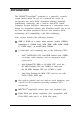
Follow these steps to turn on the system: 1. Make sure all peripheral devices, such as the mouse, keyboard, and monitor, have been connected. 2. Turn on the monitor and any other peripheral devices. 3. Turn on your system by pressing the power button on the front panel. reset button power button power indicator IDE/SCSl drive indicator SCSI drive indicator 4. keyboard/mouse lock button keyboard/mouse lock indicator Verify that the power indicator light on the front panel is on.
Configuring Your System There are two programs you can use to configure your computer: the SETUP program and the EISA Configuration utility. Which one you use depends on the option cards you may have installed in your computer.
Equipment Log Use this space to record information about your system. You can refer to this section if you call for assistance.
IDE drives installed: Bay 1: Bay 2: SCSI drives installed: Bay 1: Bay 2: Bay 3: Bay 4: Bay 5: Bay 6: Other drives installed (diskette, tape, CD-ROM, etc.
Chapter 2 Running the SETUP Program The SETUP program allows you to configure your computer and set many different system options. Use SETUP to configure your computer only in the following situations: 0 You did not install any option cards or installed only ISA option cards that did not come with configuration (CFG) files 0 You are not going to use the built-in SCSI subsystem 0 You do not have a diskette drive or have disabled your diskette drive.
Your computer’s SETUP program is stored in the system BIOS ROM. You can run SETUP whenever you turn on or reset the computer, regardless of whether you have installed an operating system. Note Any settings you make using the EISA Configuration utility override those you set using SETUP. Starting the Program Follow these steps to run SETUP: 1. Turn on the computer or press the reset button. You see the memory counts for the memory test and then the power-on diagnostic tests.
Note If you ran SETUP previously and disabled the memory test prompt or the SETUP prompt, you will not see these messages. However, you can still press the spacebar to skip the memory test or press F1 to start SETUP. If the tests find a minor error or you have not yet installed your operating system, the computer beeps twice; then you see an error message and the following prompt: To To continue press: . . . . . . . SPACEBAR configure system press: . . .
Selecting Options Use the keys listed in the table below to select SETUP program options.
SETUP program options (continued) Option Settings Description Date dd month yyyy Set the current day (dd), month, and year (yyyy); automatically tracksleap years Onboard Floppy Enabled* Disabled Set to Enabled to use the built-in diskette drive controller; set to Disabled to disable the built-in controller if you are eithernot using a diskette drive or will use a controlleron an option card Diskette A Diskette B 5.25”, 360 KB 5.25”, 1.2 MB 3.5”, 720 KB 3.5”, 1.44 MB (A*) 3.5”, 2.
SETUP program options (continued) 2-6 Option Settings Description Onboard SCSI Disabled* H/W/ Only Enabled Select Disabled if you are not using the built-in SCSI controller to free up interrupt IRQ11; select H/W Only if you will not boot your system from a SCSI device connected to the built-in SCSI controller; select Enabled if you will boot from a SCSI device connected to the built-in SCSI controller (2) SCSI BIOS Mapping C0000H* C8000H EC000H If you enabled the Onboard SCSI option, you must ensu
SETUP program options (continued) Option Settings Description 800 x 600 Mode Refresh Rate 56 Hz* 60 Hz 72 Hz Select the refresh rate frequency (in Hertz) of the built-in video controllerwhen it isoperating in 800 x 600 mode; see your monitor manual to determine the refresh rate your monitor is capable of displaying 1024 x 768 Mode Refresh Rate Interlaced @ 44/88 Hz Non-Interlaced @ 60 Hz Non-Interlaced @ 70 Hz Non-Interlaced @ 72 Hz Select the refresh rate frequency (in Hertz) of the built-in video
SETUP program options (continued) 2-8 Option Settings Description Keyboard Installed Not Installed* Set to Installed to allow your computer to operate with a keyboard; set to Not Installed to use your computer without a keyboard (for example, as a network server) and allow power-on diagnostic tests to report a disabled keyboard instead of a failed keyboard Numlock on at boot Yes No* Set to Yes to turn on Num Lock mode wheneveryou turn on or reset yourcomputer; set to No to turn it off Password N
SETUP program options (continued) Option Settings Description POST Setup Prompt Enabled* Disabled Set to Enabled to display the prompt to run the SETUP program when you turn on or reset your computer; select Disabled to prevent display of the prompt. (You can still press F1 to run SETUP if you disable the prompt.) See page 2-2 for more information.
SETUP program options (continued) 2-10 Option Settings Description LCD Enabled* Disabled Set thisoption to Disabled; your system does not have an LCD screen Onboard Mouse Enabled* Disabled Set to Enabled if you have connected a mouse to the built-in mouse port; set to Disabled if you are not using a mouse (freeshardware interrupt IRQ12) or if you are using a mouse controller installed on an option card Parallel Port Address 378H: Compatible / IRQ7* Address 278H: Compatible / IRQ7 Address 378H: B
SETUP program options (continued) Option Settings Description Console Redirection to COM1 Disabled* 1200 Baud 2400 Baud 9600 Baud Set to Disabled to prevent redirection of the computer’s input and output to serial port 1; set to the speed the computer should use to copy the redirected input/output to serial port 1 Console Redirection to COM2 Disabled* 1200 Baud 2400 Baud 9600 Baud Set to Disabled to prevent redirection of the computer’s input and output to the serial port assigned as COM2; set to th
SETUP program options (continued) Option Settings Description Posted I/O Writes (7) Standard* Fast Disabled Set to Standard to improve performance by posting memory and I/O writes to the ElSA bus set to Disabled if any of your option cards do not support this feature Concurrent Refresh Enabled* Disabled Set to Enabled to improve performance by executing concurrent CPU cache and main memory refresh cycles; set to Disabled if you have trouble with any application programs while this option is enabled
2 You must also run the EISA Configuration utility to fully enable yourbuilt-in SCSl controller. 3 When you select Not Installed for the Video Type option, the display type bits are configured for VGA. 4 If you change the refresh rate, you must press the reset button or turn the computer off and then on again aftersaving your settings to reset the rate. 5 The Offboard VGA/EGA Adapter Installed option settings do not affect yourbuilt-in video controller.
Note Be sure you enter the correct drive type or parameters for your drive; if they are incorrect, the computer will not recognize your drive.
Hard disk drive types (continued) Running the SETUP Program 2-15
Exiting SETUP To exit the SETUP program, press ESC at any of the SETUP pages and follow the instructions on the screen to do any of the following: 0 To continue running SETUP, press E SC again. 0 To save your settings and then exit and reboot the computer, press F4. 0 To load default settings for all the SETUP options, press F5; the program erases any changes you have made (except for the time and date). 0 To exit SETUP without saving your settings, press F6.
Chapter 3 Running the EISA Configuration Utility The EISA Configuration utility provided with your system allows you to configure your computer when you have done or will do the following: 0 Installed EISA option cards 0 Installed ISA option cards that came with configuration files 0 Plan to use the built-in SCSI controller.
You need to run the EISA Configuration utility to configure your system with your EISA option cards installed before you use your computer. You may need to run it again later if you add or remove options, such as memory, disk drives, or option cards. After running the utility, you save the current configuration in the computer’s CMOS RAM and in a file called SYSTEM.SCI.
How to Use This Chapter This chapter is divided into the following four sections: The Configuration Process describes the various aspects of configuring your computer with the EISA Configuration utility. It also tells you how to use the keyboard or a mouse with the program and how to use on-line help. Configuring Your System provides step-by-step instructions for running the EISA Configuration utility and is organized in the order in which you should perform the operations.
The Configuration Process This section describes the following configuration operations: 0 Using the configuration files 0 Using the keyboard or a mouse with the program 0 Using on-line help Using Configuration Files Configuration (or CFG) files provide information to the system about a card’s functions and resource requirements so your computer can allocate its resources efficiently. They also provide instructions for setting any switches and jumpers on ISA cards.
Using the Keyboard If you use a keyboard when you run the EISA Configuration utility, refer to the table below for a description of the keys you can use to move the cursor and select items. If you’ll be using a mouse with the program, see “Using a Mouse” below. Most of the screens show which keys you can press to perform various operations. Follow the instructions on each screen. Whenever the icon is highlighted, press Enter to select .
To select most options, place the cursor on the option, click once to highlight it, and again to select it. When you see ‘/‘or & on the side of a screen, you can scroll the text. Place the cursor on the arrow indicating the scroll direction and hold down the mouse button. Release it to stop. Keep in mind that this chapter gives keyboard instructions when describing how to use the EISA Configuration utility. You should substitute the appropriate mouse equivalents when performing the same operations.
Configuring Your System Follow the instructions in this section and on your screen to configure your computer using the EISA Configuration utility Configure your system in the following order: Set the date and time When you add an option card, select the Add or remove boards option to copy the necessary configuration files Use the view or edit the details of your configuration option to define your configuration View or print your jumper and switch settings Save the configuration as you exit the program.
3. Press Enter. You see the Main Menu: Main Menu Learn about configuring your computer Configure computer Set date Set time Access System Utilities Maintain system configuration diskette Exit from this utility 4. For an overview of the configuration process, highlight Learn about configuring your computerand press Enter. When you have finished reading the three Help screens, press Enter to return to the Main Menu. (You can press F10 to return to the Main Menu at any time.
Follow these steps to set the date and time: 1. At the Main Menu, select Set date. You see a prompt such as the following: Date 12-12-1994 (mm-dd-yyyy) 2. The current setting for Date is highlighted. Correct it as necessary. You can use the arrow keys to move the cursor and overtype the date. Then press Enter. 3. At the Main Menu, select Set time. You see a prompt similar to the date prompt. 4. You can use the arrow keys to move the cursor and overtype the time. Then press Enter.
Note If you installed EISA option cards in your system, the program first asks you to insert a diskette containing a CFG file for the EISA card. Remove the System Configuration diskette, insert the appropriate configuration diskette, and press Enter. Follow the instructions on the screen to complete the installation and then go to the next step. 3-10 2. Select Step 1 and read the information displayed on your screen about configuring your system.
Adding or Removing a Board Select Step 2: Add or remove boards when you need to add or remove an option card. The program displays a list of the computer’s slots with a description of any cards that it detects. The computer automatically detects EISA cards, but you must add the necessary ISA card information. Follow the instructions on the screen to add, move, or remove an option card. When you add an option card, you need the configuration diskette that came with the card.
If you add any EISA option cards to your system, various configuration options for the card(s) appear on the screen following the system board options. See your EISA option card documentation for information about configuring your card(s). The table below describes the settings available for each of the system board options. The numbers in parentheses refer to notes at the end of the table.
System board options (continued) Option Settings Description Cache Control Cache Write Cache Write Cache Set to Enabled-Write Through Mode to enable caching on the 486DX2/66 CPU card; set to Enabled-Write Back Mode to enable caching on any of the single or dual-Pentium CPU cards set to Disabled to prevent caching when you are using time-dependent software. You can also turn cache control off and on using the EISA System Utilities; see Chapter 4.
System board options (continued) Option Settings Description Hard Drive 1 and Hard Drive 2 Drive Type nn Hard Drive n Disabled* Set to the hard disk drive type of the specified IDE hard disk drive or set to user-definable drive types (2, 3, 48, or 49) and enter parameters according to the drive’sdocumentation; see “Hard Disk Drive Types’ on page 3-25 (1) Parallel Port Base Address Compatible* Base Address Bidirectional Base Address Compatible Base Address Bidirectional Disabled Select one of the Com
System board options (continued) Option Settings Description COM1 Redirection Disabled* 1200 Baud 2400 Baud 9600 Baud Set to Disabled to prevent redirection of the computer’s input and output to the serial port assigned to COM1; set to the speed the computer should use to copy the redirected input/output to the serial port assigned to COM1 COM2 Redirection Disabled* 1200 Baud 2400 Baud 9600 Baud Set to Disabled to prevent redirection of the computer’s input and output to the serial port assigned to
System board options (continued) 3-16 Option Settings Description Onboard Video BIOS Mapping To E0000h* To C0000h Disabled Select To E0000h to map the onboard video BIOS to memory address E0000h; select To C0000h to map the video BIOS to address C0000h forcompatibility with older application software; this option isautomatically set to Disabled if you disable the Onboard Video Controller option, asdescribed above; the video BIOS shadow optionsare automatically set to Enabled at eitheraddress based on
System board options (continued) Option Settings Description Shadow C0000h - C7FFFh C8000h - CFFFFh E0000h - E7FFFh Enabled (E0000h - E7FFFh*) Disabled (C0000h - C7FFFh and C8000h - CFFFh*) Set to Enabled to shadow ROM data to the specified memory addressrange in RAM; set to Disabled to leave data in ROM Keyboard Control Enabled* Disabled Set to Enabled to allow your computerto operate with a keyboard; set to Disabled to use your computer without a keyboard (for example, as a network server) and all
System board options (continued) 3-18 Option Settings Description NumLock Boot State ON at Boot OFF at Boot* Select ON at Boot to enable Num Lock mode whenever you turn on or reset your computer; select OFF at Boot to disable it I/O Recovery Time Standard Enhanced* Select Enhanced to set fast I/O recovery times; set to Standard if you have trouble with an application program or option card that is running in enhanced mode Posted I/O Writes Standard* Fast Disabled Set to Standard to improve perf
System board options (continued) Option Settings Description POST Memory Test Prompt Enabled * Disabled Set to Enabled to display the skip memory test prompt when you turn on or reset your computer; select Disabled to prevent display of the prompt (You can still press the spacebar to skip the test if you disabled the prompt; see Chapter 2) POST Setup Control Enabled -Prompt for setup entry * Enabled -Suppress setup prompt Setup Disabled Select Enabled -Prompt for setup entry to display the prompt to
The options described in the table below appear on the View or edit details screen only if you are running the EISA Configuration utility in Advanced mode. See “Using Special Modes” on page 3-31 for more information.
Advanced mode system board options (continued) Option Settings Description Slot 4 A EN Control EISA Compatible* ISA Compatible When dot 4 is set to EISA Compatible, it uses the ElSA geographicaladdressing scheme. If you set dot 4 to ISA Compatible, it allowsall types of I/O accesses that may be required by option cards addressed in the range 0-255. * Default setting The options described in the next two tables configure the built-in SCSI controller and your SCSI devices.
Built-in SCSI controller options (continued) 3-22 Option Settings Description Data FIFO Threshold 100%* 75% 50% 00% This option sets the percentage of data FIFO used by the controller to match SCSI and host system data trader rates The default setting of 100% is usually sufficient.
Built-in SCSI controller options (continued) Option Settings Description Primary Channel Selection A* B Selects the order the system uses as it scans the SCSI channelsat BIOS or driver initialization * Default setting For the options described below, press Enter at the main option to access the BIOS Configuration, Device Configuration, and Utilities options.
BIOS/Device Configuration and Utilities options (continued) Option Settings Function Extended Translation for Drives> 1G Byte Enabled* Disabled Select Enabled if you install hard diskslarger than 1GB (up to 8GB) to extend translation to the drive by bypassing the DOS 1024 cylinder limit; if enabled and the drive is less than 1GB, the system translates it to 64 heads 32 sectors pertrack; ifgreater than 1GB, the translation is 255 heads, 63 sectors per track; select Disabled if you do not need extended t
BIOS/Device Configuration and Utilities options (continued) Option Settings Function Utilities option Disk Format Utility This utility performs a low-level format on your SCSI hard disk and/or checksthe disk for defects be sure to save your configuration, reboot your system, and restart the EISA Configuration Utility before you run this utility * Default setting ** Removable drives treated as fixed disks are allowed by the BIOS, but you cannot remove the media during operation.
Hard disk drive types 3-26 24 830 10 -1 26 105MB 25 751 8 -1 17 49MB 26 755 16 -1 17 100MB Running the EISA Configuration Utility
Running the EISA Configuration Utility 3-27
Using Advanced Configuration Options To perform advanced configuration operations, press F7 at the View or edit details screen. You see the Advanced menu: Lock/unlock boards View additional system information menu Set verification mode menu Maintain SCI files menu The table below describes the operations you can select from the Advanced menu and its submenus.
Advanced configuration options (continued) Advanced menu option Submenu option Set verification mode menu Automatic Sets the program to automatically check for resource conflicts and report them, if they occur (default setting). Manual Sets the program so it does not check for resource conflicts unless you select the Verify option that appears on the View or edit details screen. (The Verify option appears only if you have selected Manual verify.
If you run the EISA Configuration utility on a non-target computer (an IBM AT compatible computer or another EPSON EISA computer), you can create a file for the target computer. Then you can transport the alternate SCI file to the target computer, load it, and save it in that computer’s CMOS RAM. To create an alternate SCI file, follow the guidelines in the next section. To load an alternate SCI file when you need to use one, see “Loading an Alternate SCI File” below.
Loading an Alternate SCI File To load an alternate SCI file and store it in the target computer’s CMOS RAM, follow these steps: 1. Select Maintain system configuration diskette from the EISA Configuration utility Main Menu. 2. Select Load a backup SCI file. 3. Select the alternate SCI file you want to load from the list of SCI files displayed on the screen. 4. Exit and save the SCI file in the computer’s CMOS RAM.
The SD command starts the EISA Configuration utility and also allows you to run any of the other utilities available on the Access to other utilities menu. The CF command also starts the EISA Configuration utility, but you cannot run any other utilities. You can run the utilities in different modes by including one or more parameters on the SD or CF command line, as described in the next sections.
The table below describes the parameters you can use to modify the way the program runs on your computer. Note To run the EISA Configuration utility in non-target modeling mode, add the /N parameter to the command line. Modeling mode only affects the way the configuration utility operates; it does not affect any of the other utilities you can run using the SD command.
SD command parameters (continued) Parameter Mode Function /K Keyboard only mode Sets the program so a mouse cannot be used, even if you have installed one. In default mode, you can use a mouse as long as a mouse driver is loaded. /M Monochrome display mode Displays the program in black and white only. In default mode, color monitors will display in color. Run the program in this mode if you have redirected the console output to a serial port.
2. Then type the following and press Enter to start the program : CF [parameters] The table below describes the parameters you can use to modify the way the utility runs on your computer. CF command parameters Parameter Mode Function IA Advanced mode Enables four advanced options for the system on the View or edit detailsscreen; see page 3-28 for more information.
CF command parameters (continued) Parameter Mode Function /M Monochrome display mode Displays the program in black and white only. In default mode, color monitors will display in color. Run the program in this mode if you have redirected the console output to a serial port. /N Non-target modeling mode Allows you to run the EISA Configuration utility in non-target modeling mode; see page 3-31 for more information. Suppress reboot mode Exits the program without rebooting the computer.
Chapter 4 Using Your Computer This chapter describes the following operations: q Working comfortably 0 Locking the computer’s cover 0 Locking the front panel door 0 Disabling the keyboard and mouse 0 Using the password features q 0 Locking the keyboard Changing the processor speed 0 Controlling the speaker 0 Controlling the cache 0 Using the security features 0 Installing the video drivers and utilities 0 Using the SCSI subsystem q 0 Using special configurations Operating the computer from a rem
Working Comfortably If you spend a lot of time at your computer, you may experience occasional fatigue or discomfort caused by repetitive motions or too much time spent in one position. If you follow the guidelines in this section, you may avoid these problems and actually increase your productivity.
Since you’ll be sitting most of the time you use your computer, it’s important to have a good chair. An adjustable chair allows you to support your body in the correct position. Make sure the chair supports your lower back; the backrest should fit the curvature of your spine. To reduce fatigue, try to use a chair with adjustable, padded armrests so you can occasionally rest your arms while you work. Make sure the seat and backrest are wide enough so you can sit in a variety of positions throughout the day.
Try placing any source documents you are using on a copy stand and position the stand next to the screen at the same eye level. This reduces neck strain and makes it easier for your eyes to move back and forth between the document and the screen. Lighting Your Workspace Appropriate lighting increases your comfort and productivity, and it’s good for your eyes. Arrange your computer and light sources to minimize glare and bright reflections.
Try to keep your fingers parallel with your forearms to prevent straining your wrists. Adjust the angle of the keyboard so the slope is no more than 25 degrees. (The keyboard has legs on the bottom which allow you to adjust the angle.) Keep your hands and fingers relaxed when you are typing and try not to hit the keys too hard; using too much force creates tension in your hands. Remove your hands from the keyboard when you are not using it and take frequent breaks to stretch your hands and fingers.
0 Change your sitting position frequently throughout the day to avoid muscle fatigue. Take periodic breaks; stand up, stretch, and move around. Locking the Computer’s Cover You can lock the cover onto the computer to prevent unauthorized users from accessing its internal components. To do this, you need a padlock that fits through the hole in the lock block on the computer’s back panel. When the padlock is in place, the cover on the computer cannot be removed.
Locking the Front Panel Door You can lock the door that covers your computer’s front panel to prevent unauthorized users from accessing these components: 0 Diskette, tape, CD-ROM, or other external drives 0 Power and reset buttons 0 Keyboard/ mouse lock button Your computer comes with two keys that you can use to lock the front panel door. Open the front panel door and remove the keys from the bag taped to the inside of the door.
Disabling the Keyboard and Mouse You can disable the operation of your computer’s keyboard and mouse to prevent unauthorized users from executing any keyboard or mouse commands. To do this, press the keyboard/ mouse lock button on the front panel, as shown below. The computer disables the keyboard and mouse, and illuminates the keyboard/ mouse lock indicator light.
Using the Password Features You can set three types of passwords to provide security for your computer: 0 Power-on password 0 Network password 0 Keyboard password. The power-on password prevents unauthorized users from using your system by requiring you to enter the correct password every time you turn on or reset the computer.
Setting Passwords There are two ways to set a power-on password: 0 Using the SETUP program 0 Using the EISA System Utilities. To set a power-on password in SETUP, follow the instructions in Chapter 2 for starting and running the program. Select the Password option on the second page of SETUP options and follow the instructions on the screen to set a password. You must run the EISA System Utilities to set a network and keyboard password, but you can also use it to set a power-on password.
Setting a power-on password To set a power-on password, follow these steps: 1. Select Set Initial Power-on Password at the Password Utility Menu. 2. You see a prompt to enter a password of up to seven characters. Follow the instructions on the screen to enter the password twice and return to the Password Utility Menu. 3. Your power-on password is also now your keyboard password. If you want to set a different keyboard password, see “Setting a keyboard password” below.
Setting a keyboard password Once you set a power-on password, it automatically becomes your keyboard password as well. If you want to use a different password for the keyboard, you can set one with the Set Keyboard Password option. This password takes effect only temporarily, however; when you turn off your computer, the power-on password again becomes your keyboard password.
Follow these steps to enter a power-on password: 1. When you turn on your computer, press the reset button, or press Ctrl Alt Del, you see the following prompt: Enter password: 2. Type your password and press Enter. The screen does not display what you type. After you enter the correct password, you see Password and the computer loads your operating system. OK If you do not enter the correct password, you see Password is incorrect and another prompt to enter the password.
There are several methods you can use to change or delete a keyboard password. See the appropriate section(s) below to change or delete your password(s). Changing ordeleting a power-on password To change or delete a power-on password, follow these steps: 1. Turn on the computer, press the reset button, or press Ctrl Alt Del. You see the following prompt: Enter password: 2. To change the password, type the current password followed by a forward slash (/).
Changing ordeleting a keyboard password If your keyboard password is the same as your power-on password, follow the steps in the section above to change or delete it. Then reboot your system. If your keyboard password is different from your power-on password, you can make both passwords the same by turning off or resetting your computer. To temporarily change your keyboard password to something other than your power-on password, follow these steps: 1.
Locking the Keyboard You can temporarily lock the keyboard to secure your system when you are going to leave it unattended. Then, when you return, you can enter a special keyboard password to unlock it. To lock your keyboard, you must first set a keyboard password, as described on page 4-12. Then follow these steps whenever you want to lock your keyboard: 1. To start the EISA Configuration utility, insert the System Configuration diskette in drive A. 2. Log onto drive A and type SD.
When you are ready to use your computer again, type your keyboard password and press Enter. You see the Password Utility Menu. If you enter an incorrect password, the prompt remains on the screen. Try entering it again; you can try as many times as you want. 7. Follow the instructions on the screen to exit the EISA Configuration utility. Changing the Processor Speed Your computer’s processor can operate at two speeds: high and low.
Entering Keyboard Commands To change the processor speed, enter one of the keyboard commands shown in the table below. Keyboard Feed setting commands Key command Function Ctrl Alt 1 Changesthe speed to low (simulated 8 MHz) Ctrl Alt 2 Changesthe speed to high You must use the 1 or 2 key located on the numeric keypad. When you set the speed to low, you hear a low tone from the computer’s speaker; when you set it to high, you hear a high tone.
Using the EISA System Utilities You can temporarily change the processor speed using the EISA System Utilities. This method is convenient if your application program does not recognize the Ctrl Alt key commands to change the processor speed. Follow these steps: 1. Insert the System Configuration diskette in drive A. 2. Log onto drive A and type SD. Press Enter at the next two screens to bring up the Main Menu. 3. Select Access System Utilities from the Main Menu.
Controlling the Speaker You can enable or disable the computer’s speaker using the following three programs: 0 SETUP 0 EISA Configuration utility 0 EISA System Utilities. Both the SETUP program and the EISA Configuration utility allow you to define the default setting for the speaker. Follow the instructions in Chapters 2 and 3. If you want to change the default setting temporarily, use the EISA System Utilities, as described below.
4. Select Speaker ON or Speaker OFF. You see a message confirming the new setting. 5. Press Enter to return to the System Utilities Menu. Then follow the instructions on the screen to exit the EISA Configuration utility. The setting you define remains in effect until you turn off or reset the computer, or until you change it to a different setting.
If you want to change the default setting temporarily, use the EISA System Utilities, as described below. Then, whenever you turn off or reset the computer, the setting returns to the default setting you selected in the SETUP program or the EISA Configuration utility. 1. To start the EISA Configuration utility, insert the System Configuration diskette in drive A. 2. Log onto drive A and type SD. Press Enter at the next two screens to bring up the Main Menu. 3.
Using the Security Features Your computer comes with several security features that allow you to prevent access to the computer hardware and software. You may want to use one or more of the following features to ensure that your system is secure: Set passwords. You can create unique power-on, network, or keyboard passwords to prevent unauthorized users from accessing your computer when it is operating. See page 4-9 for complete instructions. Lock the keyboard and mouse.
You might want to use several of these features together, depending on the level of security you need for your computer. For example, if you rarely plan to leave the computer unattended, you may use only the keyboard/ mouse lock button. However, if you plan to operate the computer in a remote location, you may want to set the main system board jumpers and lock the cover and front panel door. Try the combination of features that is best for you.
3. Follow the instructions on the screen to install the drivers for the applications you plan to use. Installing Windows 3.1 Drivers Before you install the Windows video drivers, install the Windows program on your computer’s hard disk drive. Then follow these steps to install the drivers: 1. Start the Windows Program Manager. 2. Insert the Video Drivers for Microsoft Windows diskette in drive A. 3. Select File from the menu bar. 4. Select Run. 5. In the Command Line box type A: ~WDSETUP. 6.
If you want to change the installed drivers, perform steps 1 through 6 above. Then click on the blue icon in the upper right corner of the window. Choose a new driver and click on Restart Windows. Using the SCSI Subsystem This section describes the basic operations you need to perform to use your computer’s built-in SCSI II subsystem.
Installing SCSI Terminators Your SCSI devices communicate with each other and with the controller along the SCSI bus. For each SCSI bus you use (channel A and channel B), you must mark both “ends” of the bus with SCSI terminators. The ends of the bus are the first device on one end of the bus (such as your SCSI interface) and the last device on the other end (such as a SCSI hard disk drive). You usually install a terminator on the printed circuit board of a SCSI device.
Configuring the SCSI Subsystem You can easily configure the SCSI controller, BIOS, and devices for both channels using the EISA Configuration utility on your computer’s System Configuration diskette. The EISA Configuration utility includes a SCSI disk formatting utility so you can format your SCSI devices as you configure your system. See Chapter 3 for instructions on using the EISA Configuration utility to configure your SCSI subsystem.
Using Special Configurations If you are going to use your computer without a major component-such as a keyboard, monitor, or diskette driveyou must take some steps to ensure that your system operates correctly. Be sure to do the following, depending on which component you will not use: Install your monitor, keyboard, and, if necessary, diskette drive as you set up your computer so you can run the SETUP program or EISA Configuration utility.
Operating Your Computer from a Remote location If you want to operate your computer from a remote location, you must redirect your computer’s input and output functions to one of the serial ports. To do this, set one of the console redirection options for COM1 or COM2 in either the SETUP program or the EISA Configuration utility. See Chapters 2 and 3 for instructions.
Chapter 5 Accessing Internal Components To access your computer’s internal components, you need to remove two system covers, the external side cover and the internal main system board cover. If you are going to install an externally accessible device in the external drive bays, you also need to remove the computer’s front panel. This chapter describes how to remove and replace these items. Be sure to read the following important safety precautions before you begin.
If you are not properly grounded, you could conduct static electricity and damage your equipment. Be sure to ground yourself by touching the inside of the computer’s back panel before you touch any of the internal components. Refrain from shifting your feet once you have grounded yourself-it is easy to pick up static electricity from carpeting Do not touch any components except those that this manual instructs you to touch.
Removing the External Side Cover Follow these steps to remove the external side cover: 1. If you installed a padlock or a cable lock to lock the side cover onto your computer, remove the lock now. 2. The left side of the computer is a cover secured by two screws at the rear of the system, as shown below. Remove these screws and set them aside. handle 3.
Removing the Internal Main System Board Cover Once you remove the system’s external side cover, you see a metal cover protecting the main system board. You need to remove this cover to access the main system board and to perform such tasks as: 0 Installing or removing option cards 0 Changing jumper settings 0 Installing or removing memory modules 0 Installing or removing drive cables connected to option cards or the main system board. Follow these steps to remove the main system board cover: 1.
2. Open the cover by pulling it toward you until the curved tabs disengage from the computer’s back panel. 3. Lift the cover out of the computer and set it aside. Replacing the System Covers Before replacing the internal main system board cover, make sure you left no tools or loose parts inside the computer case. Also make sure that all spare or loose power and device cables are securely tucked into the space beneath the upper hard disk drive bays or above the lower SCSI drive bays.
5-6 3. Rotate the cover toward the system board and align all six screw holes, as shown below. 4. Attach the cover to the computer with the six screws you removed earlier.
Replacing the External Side Cover Follow these steps to replace the external side cover: 1. Position the cover over the computer case so that the edge with the handle protrudes about an inch beyond the back of the computer. Align the tabs at the top and bottom of the cover with the notches in the computer case. tabs bottom notch and tab 2. Slide the cover toward the front of the system so that the tabs engage in the notches. 3. Replace the two side cover retaining screws you removed earlier. 4.
Removing the Front Panel The upper front panel consists of an inner panel and a door. If you need to install or remove any devices in the external drive bays, you must remove the front panel. Follow these steps: 1. If you locked the front panel door, follow the steps in Chapter 4 to unlock it. 2. Open the front panel door almost all the way. 3. Gently strike the top edge of the door with the palm of your hand to disengage the front panel from the computer. Gently Strike here 4.
Replacing the Front Panel Follow these steps to replace the computer’s front panel: 1. Position the front panel so that the four small square tabs on the left side of the inner panel align with the square holes in the left side of the computer case. 2. Push the front panel against the front of the computer. 3. Gently press in on the hinge side of the front panel until it clicks into place. 4. Close the front panel door.
Chapter 6 InstaIling and Removing Options This chapter explains how to install and remove the following components: 0 CPU card 0 Option cards 0 Memory modules 0 Video RAM. You’ll also find instructions for changing the main system board jumper settings and for using the VGA feature connector. Before you perform any of the steps in this chapter, follow the instructions in Chapter 5 to remove the computer’s side cover and the main system board cover.
Main System Board Map As you follow the instructions in this chapter and in Chapter 7, use the illustration below to locate the necessary components on your main system board.
Removing the CPU Card The CPU card contains your system’s microprocessor(s) and cache memory. The card plugs into a proprietary slot on your main system board. You may need to remove your card to replace it with a new card or to access other components on the main system board. Before you can remove the CPU card, you must first remove the retaining bracket that holds it in place. Follow these steps: 1.
2. Continue sliding the bracket forward a couple of inches until it stops; then pull the slotted end toward you and to the left until the narrow tip of the bracket comes out of its hole. Set it aside. 3. Carefully pull the CPU card straight out of its connectors on the main system board. Do not rock the card from side-to-side or you will damage the connectors. Be sure not to touch any of the card’s components or the gold connectors; handle it only by the edges.
2. To replace the CPU card retaining bracket, position it so its narrow tip faces the front of the computer and the slotted end points to the rear. Also make sure the side with three protruding tabs faces out, as shown below. holes narrow tip slotted end protruding tabs 3. Insert the narrow end of the bracket into its hole (as shown above) until it stops. 4. Guide the bracket over the edge of the CPU card and slide the slotted end toward the hole in the back of the computer. 5.
Installing the Dual-Pentium 66 ASIC Chip Follow these steps to install the ASIC chip that came with your dual-Pentium 66 CPU card: 1. Locate the ASIC socket on the main system board using the illustration on page 6-2. Caution To avoid generating static electricity and damaging the ASIC chip or other components on your main system board, ground yourself by touching the metal surface on the inside of the computer’s back panel. Then remain as stationary as possible while you install the chip. 6-6 2.
Installing an Option Card This section explains how to install an option card in one of your computer’s eight EISA bus master expansion slots. It usually does not matter which slot an option card occupies as long as the card fits in the slot. For example, if you have an 8-bit card with an additional tab along the bottom, it will not Fit in any of the option slots in your computer.
If you are installing a high-resolution graphics adapter card that connects to a VGA feature connector, follow the instructions below to install the adapter card; then see “Using the VGA Feature Connector” on page 6-10 to connect the card to the VGA feature connector in your computer. Follow these steps to install an option card: If this is the first time you are installing a card in the option slot, you need to remove the metal cover for that slot.
4. Hold the card along the top corners and guide it into the slot, as shown below. (If you are installing a full-length card, insert the front edge of the card into the corresponding guide on the right.) top corners connector Once the connectors reach the slot, push the card in firmly (but carefully) to insert it completely. You should feel the card fit into place. If it does not go in smoothly, do not force it; pull it all the way out and try again. 5.
Removing an Option Card You may need to remove an option card installed in your computer to access components on the main system board, such as jumpers. You also may want to remove a card if you no longer need it or want to replace it. Follow these steps: 1. Remove the retaining screw that secures the option card to the computer. Then pull the card straight out of its slot. 2. Set the card aside with the component side facing up. 3.
3. Attach the other end of the graphics card cable to the VGA feature connector (J0410) on the main system board, shown on page 6-2. Note You do not need to change any jumpers to disable the built-in VGA adapter if you connect your graphics adapter card to the feature connector. Memory Modules Your computer comes with 8MB of memory installed on two 4MB memory modules on the main system board.
0 Fill each bank with two SIMMs of the same size. 0 Install SIMMs in Bank 0 first (sockets J0550 and J0551). Then use Bank 1 (sockets J0650 and J0651). The table below lists some sample memory configurations. Sample SIMM configurations Once you have determined where to add SIMMs, follow the instructions below to install them. Installing Memory Modules Refer to the illustration on page 6-2 to locate the SIMM sockets on the main system board.
Follow these steps to install a SIMM: Hold the SIMM so the notched edge faces the computer’s back panel and place it in the socket at an upward angle of about 45 degrees relative to the main system board. Push the SIMM into the socket until it is seated firmly. Then tilt it up until it is 90 degrees relative to the main system board and clicks into place, as shown below.
5. The next time you turn on your computer, run the SETUP program or the EISA Configuration utility to enable the computer to recognize the additional memory. For more information, see Chapters 2 and 3. Removing Memory Modules If you need to remove memory modules from your computer, follow the steps below. Check the information on page 6-11 to be sure you remove SIMMs from the correct sockets. If you need to remove SIMMs from your computer, follow the steps below : 1.
Caution Apply only enough pressure on the retaining clips to release the SIMM; too much pressure can break the plastic retaining clips or damage the socket. 2. Remove the SIMM from the computer and store it in an anti-static package. 3. If you wish to remove additional SIMMs, repeat steps 1 and 2, making sure you empty the sockets in the following order: J0651, J0650, J0550, and J0550. 4.
The table below lists the video DRAM DIP chips that are approved for use in your computer. Video DRAM DIP chip types Manufacturer Part number Hyundai HY534256AS60 HY534256A LS60 Fujitsu M 881 C4256A-60P Mosel Vitalic V53C 104FP-60L V53C 104FP-60 Samsung lUvl44C 256C P-6 Note that your video memory sockets may not look exactly like the ones shown here. If you’re not sure how to install video memory chips, contact your EPSON dealer or Authorized EPSON Servicer and ask for assistance. 1.
4. Position one of the memory chips over the socket as shown below, aligning the pins on the chip with the holes in the socket. Make sure the small notch on the end of the chip aligns with the corresponding notch in the socket. notches 5. Gently press the chip halfway into the socket (to make sure it is correctly aligned). If the chip does not go in smoothly, remove it and try again. 6. When the chip is properly positioned, push down firmly on both ends to make sure it is well-seated. 7.
Setting Main System Board Jumpers The jumpers on your main system board allow you to control the following computer operations: 0 Recover the system BIOS if it becomes corrupted 0 Enable or disable the built-in video controller 0 Write-protect the diskette drive(s) 0 Set the factory defaults for non-volatile RAM (NVRAM) 0 Enable or disable the password function 0 Set the SIMM sockets to accept standard or high capacity SIMMs 0 Write-protect the configuration information in the FLASH memory 0
The table below lists the jumper settings and their functions.
Main system board jumper settings (continued) Description Jumper setting Function E0720 Video memory size 1 to 2* 2 to 3 512KB of video memory 1MB of video memory installed E0721 FLASH memory write protection 1 to 2* Enables writes to FLASH memory using the EISA Configuration utility or the SETUP program Disables writes to FLASH memory Jumper number 2 to 3 E0722 Video controller base address 1 to 2* 2 to 3 Movesvideo controllerstarting address to 03C3H if you installed a card orapplication p
Chapter 7 Installing and Removing Disk Drives The instructions in this chapter describe how to install and remove optional drives in your computer. You can use these instructions to install a variety of devices, including diskette drives, hard disk drives, SCSI drives, tape drives, and CD-ROM drives. Although your drive may look different from the ones illustrated here, you should be able to install it the same way.
Using the Correct Drive Bay Your computer contains nine bays that allow you to install various drive types in the following configurations: Three externally accessible bays for mounting half-height 3.5-inch or 5.25-inch drives that use removable media. The system comes with a 3.5-inch diskette drive installed in the top external bay. Four lower internal bays for mounting either four half-height or two full-height 3.5-inch SCSI drives.
If you are installing a hard disk, it is best to install it in an internal drive bay. This reserves the external bays for any externally accessible drives you may want to add later. Note Installing a hard disk drive in an externally accessible bay is not recommended because the drive can generate excess electromagnetic interference. You can install 5.25-inch drives or 3.5-inch drives with 5.25-inch mounting frames attached in the external bays.
3. Using two screws and the grounding clip, attach plastic slide rail B to the left side of the drive and slide rail A to the right side of the drive. Position each slide rail so its narrow end is at the front of the drive with its tab facing outward, as shown below. Then install a grounding clip on each side under the two screws nearest the front of the drive. slide rails 4. If you have not already done so, remove the front panel from the system as described in Chapter 5. 5.
6. Hold the drive in front of the system and connect the power cable to the drive. Position the cable connector so that its holes fit over all the pins in the drive and then push in the connector. 7. While holding the drive in front of the system, connect the appropriate ribbon cable to the drive, as described below. If you are reinstalling a diskette drive in the top external bay, use ribbon cable P3.
8. Position the drive so that the plastic slide rails on each side fit between the guide rails inside the drive bay, as shown below. Then push the drive into the bay until the slide rails lock in place.
9. If you installed a device that uses removable media, such as a diskette drive, you need to remove the appropriate slot cover from the computer’s front panel. Remove the two screws that secure the slot cover to the inside of the front panel, as shown below. Then remove the slot cover and store it in a safe place. 10.
Removing a Drive from an External Bay Follow these steps to remove a drive from an external bay: 7-8 1. If you have not already done so, remove the front panel from the system as described in Chapter 5. 2. Notice the tabs on the end of the slide rails attached to each side of the drive. To release the drive, press both tabs in toward the drive and pull the drive partially out of the bay.
3. While holding the drive in front of the system, disconnect the power and ribbon cables attached to the drive. Grasp the cable connector and pull it straight out from the drive so you do not damage the connector; do not pull on the cables. 4. If necessary, remove the slide rails and grounding clips from the drive. Set them and the screws aside for safekeeping 5. Replace the front panel slot cover, if necessary. 6. Replace the front panel as described in Chapter 5.
Removing the IDE Drive Bay Assembly Follow these steps to remove the IDE drive bay assembly: 1. Remove any cables that are connected to any drives already installed in the IDE drive bay assembly. 2. While supporting the IDE drive bay assembly, remove the screw that attaches it to the computer case at the top of the bay, as shown below. 3. The other end of the drive bay assembly is secured to the computer by two anchor tabs inserted into slots in the side wall.
Installing an IDE Drive If you are installing a half-height IDE hard disk drive, you can install it in either the top or bottom bay. If you are installing a full-height IDE drive, you must first remove any half-height drives from the drive bay assembly so the full-height drive can use both bays. The figures in this section illustrate a half-height IDE drive installation. 1. Turn the drive bay assembly over and install the drive so that the component side is facing up, as shown below.
Caution If you are installing a second drive in the drive bay assembly, be careful not to scrape or damage the components on the installed drive. 3. If you need to install a second IDE hard disk drive, repeat step 2. 4. Follow the instructions on page 7-13 to replace the IDE drive bay assembly. Removing an IDE Drive Follow these steps to remove a hard disk drive from the IDE drive bay assembly: 1. 7-12 Remove the four screws that attach the drive to the assembly.
2. Remove the drive from the bay and place it on an anti-static surface. 3. If you are removing one IDE drive but leaving another in the system, you need to change the jumper settings on the remaining drive. See the documentation that came with your drive for instructions on changing the jumpers. 4. Replace the IDE drive bay assembly as described below. Replacing the IDE Drive Bay Assembly Follow these steps to replace the IDE drive bay assembly: 1.
3. Lift up the front end of the assembly and attach it to the top of the computer case with the screw you removed earlier. 4. Connect the ribbon and power cables as described in the next section. Connecting the IDE Ribbon and Power Cables This section explains how to connect ribbon and power cables to your IDE drive(s). The ribbon cable transmits data and the power cable carries electric current to the IDE device. The IDE ribbon cable includes three connectors: P1, P2, and P3.
If your system did not come with an IDE drive already installed, the ribbon cable came in the box with your computer and you must first connect it to the computer’s main system board. Follow the steps below beginning with step 1. 1. Connect P1 of the IDE ribbon cable to the IDE interface, J0821, on the main system board. Position the tab on connector P1 so it faces down and be sure the red stripe on the ribbon cable faces the computer’s back panel. red stripe IDE hard disk drive connector PI 2.
3. Connect P3 of the IDE ribbon cable to the drive in the top half of the drive bay assembly. Connect P2 of the IDE ribbon cable to the drive in the lower half of the drive bay assembly. (If you installed only one drive, connect P3 of the IDE ribbon cable to the drive.) Align the tab on the connector with the notch in the drive’s socket. Be sure the red stripe on the IDE ribbon cable faces the computer’s front panel.
4. Connect power cable P7 to the power socket of the drive in the top half of the drive bay assembly. Connect power cable F6 to the drive in the lower half of the drive bay assembly. (If you installed only one drive, connect either P6 or P7; it does not matter which one.) Be sure to position the connector so that its notched corners line up with the notched corners of the socket on the drive. Make sure the holes fit over all the pins and then push in the connector. 5.
Installing a SCSI Drive Your computer supports a variety of single-ended SCSI devices. If you plan to install one to four SCSI drives, use only the SCSI (lower) internal bays. If you plan to install more than four, you can install the fifth and sixth drives in the upper internal bays or in the external drive bays, if the drives use removable media. Before you begin, locate two slide rails and two grounding clips for each drive you will install. These items came in the box with your computer.
Follow the steps below to install the SCSI drive(s) in your computer. If you are using the internal SCSI subsystem, start with step 4 below. If you plan to install an external SCSI adapter card, start with step 1. 1. Follow the instructions in your SCSI adapter documentation to set any jumpers or switches on the adapter card. Then see “Installing an Option Card” in Chapter 6 for instructions on installing the adapter in your computer.
5. Record the drive’s model, serial, and SCSI ID number in the “Equipment Log” on page 1-12. 6. Follow the instructions in the SCSI drive’s documentation to set any jumpers or switches on the drive and to install or remove the terminating resistors. Note Do not remove terminating resistors from the SCSI device you install at the end of the ribbon cable. The last device on the cable terminates the SCSI bus and must have terminating resistors installed. 7.
8. Position the drive in the bay so the components face down and the ribbon and power sockets face outward. Align each plastic slide rail with the guide rails inside the bay you plan to use; then slide the drive into the bay until the slide rails lock in place, as shown below. slide rail ribbon and powercable 9. Repeat steps 4 through 8 to install any other SCSI drives in the lower drive bays. If you installed four or fewer drives, go to the next section.
To install a fifth or sixth SCSI drive in the upper external bays, follow the instructions on page 7-3. Then return to this page for instructions on connecting the SCSI ribbon and power cables to your drive(s). Installing the SCSI Ribbon and Power Cables This section explains how to connect SCSI ribbon and power cables to your SCSI drive(s). The ribbon cable transmits data and the power cable carries electric current to the SCSI device.
If your system came with a SCSI drive, this cable is already connected inside your computer. If your computer did not come with a SCSI drive installed, this cable came in the box with your computer. Follow the steps below to connect the SCSI ribbon cable to your system board and drives. If at least one SCSI drive is installed, begin with step 3. 1. Connect P1 of the SCSI ribbon cable to the SCSI A socket on the main system board. 2.
3. Choose a connector for each SCSI drive you have installed. Align the tab on the connector with the notch in the drive socket. Make sure the holes fit over all the pins, and then push in the connector. If you are installing up to four SCSI drives, be sure to use P7 for the last drive on the bus. Then proceed to “Installing the SCSI power cables” on page 7-25. If you are installing five or six SCSI drives, continue with the next step. 4.
Installing the SCSI power cables Follow these steps to connect power cables to your SCSI drive(s): 1. You can use P8, P9, P10, or P11 to provide power to any drives you have installed in the lower internal drive bays. Position the power cable connector so that its notched corners line up with the notched corners of the power socket on the drive. Make sure the holes fit over all the pins and then push in the connector. 2.
Note If you removed the last device from your SCSI bus, be sure to reconnect ribbon cable connector P7 to the SCSI device that will now be the last device on the SCSI bus. 2. Disconnect the power cable from the power socket on the drive. 3. To remove a SCSI drive from the upper internal drive bay, first follow the steps on page 7-10 to remove the IDE drive bay assembly.
4. If necessary, remove the four screws, two grounding clips, and two slide rails from the drive and save them. 5. Repeat steps 1 through 4 for each drive you need to remove. 6. If you removed your only SCSI device(s), disconnect PI of the ribbon cable from the system board. Also check your SCSI drive documentation for any other steps you may need to perform.
Appendix A Troubleshooting If you have any problems as you set up and use your computer, refer to this chapter. You can correct most problems by adjusting a cable connection, repeating a software procedure, or resetting the computer. The troubleshooting suggestions in this chapter are organized in general categories, such as “The computer will not start.” Within each category, a more specific problem is described with possible solutions.
Use these guidelines to locate information about your system : Serial number: Look on the back panel of the computer to find the serial number. System BIOS version: Restart your system. You’ll see the system BIOS version number displayed on the screen during power-on diagnostics. System configuration: Run SETUP or the EISA Configuration utility to view your system configuration information. MS-DOS version: At the MS-DOS prompt, type VER and press Enter to see the MS-DOS version number.
error Messages Your computer’s built-in memory (ROM) contains a series of diagnostic programs, called power-on diagnostics. These programs check internal devices such as ROM, RAM, the timer, the keyboard controller, and the hard disk drive every time you turn on the computer or press the reset button. The RAM test program displays a count of the memory currently installed in your system.
The table below lists the power-on diagnostic and boot error messages, and some basic solutions to the problems. Check the appropriate section(s) in this appendix for other solutions.
Power-on diagnostic and boot error messages (continued) number Error message lumber Message Solution 745 First 64KB RAM chip or data line failure-bit 5 Contact your dealer or Servicer 746 First 64KB RAM chip or data line failure-bit 6 Contact your dealer or Servicer 747 First 64KB RAM chip or data line failure-bit 7 Contact your dealer or Servicer 748 First 64KB RAM chip or data line failure-bit 8 Contact your dealer or Servicer 749 First 64KB RAM chip or data line failure-bit 9 Contact yo
Power-on diagnostic and boot error messages (continued) A-6 Troubleshooting
Power-on diagnostic and boot error messages (continued) Troubleshooting A-7
Power-on diagnostic and boot error messages (continued) connected, the keyboard orcontroller may have failed; Not an error A-8 Troubleshooting
Power-on diagnostic and boot error messages (continued) problem persists failure at nnnn:OOOO to Memory double word logic failure at nnnn:OOOO Memory high address failure at nnnn:OOOO to Memory addressline failure at nnnn:nnnn, memory error message (above) informing you that memory modules Initialize extended BIOS Not an error Troubleshooting A-9
Power-on diagnostic and boot error messages (continued) Coprocessorfailed and check all connections; contact your dealer or servicer if the problem persists 131 Diskette drive 0 failure 132 Diskette drive 1 failure A-10 Troubleshooting
Power-on diagnostic and boot error messages (continued) dealer or servicer if the problem persists and check all connections; contact our dealer or servicer if Internalcache test Contact your dealer or nnnnOH optional ROM bad checksum =nn H Correct the address conflict; contact your dealer or servicer if the C8000H-C FFFFH failed 085 Shadow of BIOS at EOOOOHE7FFFH failed Contact your dealer or servicer 070 070 Time of day clock not set Run SETUP or the ECU and set the time and date 060 060 K
Power-on diagnostic and boot error messages (continued) Error Countdown message Number number Message 041* ID mismatch error; dot n The board in dot n is bad or its lD does not match what the ECU expects mismatch is due to the wrong board in dot n or the wrong configuration file for the board; run the ECU to configure dot n or, if necessary, replace the board; contact your dealer or servicer if the problem persists 042 Invalid ISA configuration information An ISA board is improperly configured; run th
Power-on diagnostic and boot error messages (continued) Error Countdown message number number Message * Solution 001 Not a bootable diskette Remove the diskette from the drive and use a bootable diskette, or boot the system from the hard disk drive; contact your dealer or servicer if the problem persists 002 No boot device available Make sure you are using a bootable diskette or that your hard disk drive isformatted; contact your dealer or servicer if the problem persists 003 Hard drive read failu
Run-time Error Messages The table below lists the run-time error messages and some basic solutions to the problems. Check the appropriate section(s) in this appendix for other solutions.
F&n-time error messages (continued) Error Countdown message Number number Message Solution 986 Unresolved bustime-out NMI The option card is defective; replace the card and run the ECU; contact your dealer or servicer if the problem persists 987 Bustime-out NMI; dot n Run the ECU; contact your dealer or servicer if the problem persists 988 Software NMI Run the ECU; contact your dealer or servicer if the problem persists 970 Unexpected software interrupt An error has occurred in a software utili
The tables below list the fatal and non-fatal error codes Error tone codes for fatal errors Error tone code Description 1-1-3 Real-time clock write/read failure 1-1-4 ROM BlOS checksum failure 1-2-1 Programmable interval timerfailure 1-2-2 DMA initialization failure 1-2-3 DMA page register write/read failure 1-3-1 RAM refresh verification failure 1-3-3 First 64KB RAM chip or data line failure (multi-bit) 1-3-4 First 64KB RAM odd/even logic failure 1-4-1 First 64KB RAM addressline failure
Error tone codes for fatal errors (continued) Error tone code Description 2-4-3 First 64KB RAM failure-bit E 2-4-4 First 64KB RAM failure-bit F 3-1-1 Slave DMA register failure 3-1-2 Master DMA register failure 3-1-3 Master interrupt mask register failure 3-1-4 Slave interrupt mask register failure 3-2-4 Keyboard/mouse controller test failure Error tone codes for non-fatal errors Error tone code Description 3-3-4 Screen memory test failure 3-4-1 Screen initialization test failure 3-4-2
The computer starts but the screen is blank. See “Monitor Problems” below. The computer starts but does not boot. If the computer starts but does not load your operating system, the problem could be caused by many different factors. First make sure you have correctly formatted your hard disk and have properly installed your operating system on it. (See “Hard Disk Problems” on page A-24.
If you are running a software program, try these procedures: If your computer is processing a complicated command or performing a complex task, it may take a long time to complete its work. If the computer does not respond after a reasonable length of time, proceed to the next step. Press Num Lock. If the Num Lock indicator light on the keyboard lights up, the computer is probably still processing a command. If it does not light up, proceed to the next step.
You want to change or delete the password. See Chapter 4 for instructions on changing or deleting your password. You have forgotten the current power-on password. If you have forgotten your power-on password and cannot use your computer, follow these steps: 1. Turn off the computer, remove the system covers, and clear the password by moving the main system board jumper E0390 from position 1-2 to position 2-3.
7. Turn on your computer. When you see the prompt, press F1 to run SETUP. Follow the instructions in Chapter 2 to set a new power-on password using the SETUP program. 8. Insert the System Configuration diskette in drive A and turn on the computer. Follow the instructions in Chapter 4 to set a new power-on password using the EISA System Utilities.
Monitor Problems See the suggestions below if you have trouble with your monitor. There is no display on the screen. Make sure the monitor cables are securely connected to the monitor, the computer, and the electrical outlet. Check that the monitor’s power switch is on and that the power light on the monitor is lit. If the power light is on but you still do not see anything on the screen, check the monitor’s brightness and contrast controls. Check to see if the electrical outlet supplies power.
Diskette Problems Check to see if you inserted the diskette upside down or did not insert it all the way. If the diskette is blank, make sure it is formatted. Place the diskette in the drive of another computer and repeat the operation. If this works, the trouble may be in your diskette drive. See “Diskette Drive Problems” below. Make sure you enabled the built-in controller and selected the correct diskette drive type(s) when you ran the SETUP program or the EISA Configuration utility.
The diskette drive is making loud or unusual noises Contact your EPSON dealer or Authorized EPSON Servicer. Hard Disk Problems If you think there is something wrong with your hard disk, see the suggestions below. You have problems with a newly installed drive. If your EPSON dealer or Authorized EPSON Servicer installed the drive, consult your dealer or servicer about the problem. If you installed the hard disk yourself, make sure you carefully followed all the instructions in Chapter 7.
0 If you are sure the hard disk has been installed and prepared properly but you cannot access the drive, review the instructions in your operating system manual. Make sure you performed the necessary steps in the installation process for your configuration. 0 If you still cannot identify the problem, consult the dealer from whom you purchased the drive. You notice a reduction in hard disk performance. 0 The data on the disk may have become fragmented.
0 If you are unable to run the SETUP program or the EISA Configuration utility, make sure you have write-enabled your computer’s FLASH memory. Check to see if jumper E0721 is set to position 1-2, as described in Chapter 6. 0 If you are still having problems with your software, consult your software documentation or contact the manufacturer for technical support. Printer Problems Make sure the printer has power and is properly connected to the computer. (Also, be sure your printer has paper in it.
Check to see if you set the necessary DIP switches or jumpers on the option card. Also be sure you performed the correct setup procedures for the software you are using with the option card. See your option card manual and check your EISA Configuration utility information for the card. Check the computer’s power supply limits in Appendix B and your option card documentation to be sure you have not installed a card that exceeds the total amperage allowable in your system.
0 Be sure to run the SETUP program or the EISA Configuration utility after you install or remove memory modules to automatically update your configuration. See Chapters 2 and 3 for instructions. 0 If you are still having trouble with your SIMMs, write down any error messages you see and contact your dealer or servicer. Mouse Problems If your mouse is not working correctly, see the following guidelines. Make sure that your mouse is securely connected to its port. Make sure your mouse is not locked.
SCSI Drive Problems If a SCSI device is not working correctly, see the guidelines below. Make sure that the cables connecting any external SCSI devices are firmly inserted in their ports on the devices. Verify that you have set the correct SCSI ID numbers and properly installed the SCSI terminators. See your SCSI device documentation for more information.
Appendix B Specifications Main System Board System memory 8MB RAM standard on two 4MB SIMMs; expandable using 1MB, 2MB, 4MB, 8MB, 16MB, or 32MB single- or double-sided SIMMs up to 128MB (maximum); SIMMs must be 80ns, 36-bit, 72-pin, tin-plated, fast-page mode type; 16MB and 32MB SIMMs may be 70ns, 36-bit, 72-pin, tin-plated, fast-page mode type BIOS 256KB on two 128KB FLASH EEPROM devices for system and video BIOS Shadow RAM Automatically copies the system BIOS from ROM into RAM; shadow RAM addresses
CPU Card CPU Intel 486DX2, 66 MHz microprocessor; Intel Pentium 60 MHz or 90 MHz microprocessor; Intel Dual Pentium 66 MHz microprocessor; simulated 8 MHz processor speed selectable through software or keyboard corn m and Cache memory 8KB internal cache in the 486DX2/ 66 microprocessor; 128KB Intel cache module with write-through, two-way set associative cache memory and controller 16KB internal cache in the Pentium/60 and 90 processors; 256KB (Pentium/ 60) or 512KB (Pentium/ 90) cache module with write-
Keyboard Mini DIN, 6-pin connector for PS/2 compatible keyboard SCSI Built-in Twin Channel SCSI interface; two SCSI buses, each supporting up to seven SCSI devices, including the adapter (interface) Option slots Eight 32-bit EISA bus master expansion slots (16-bit and S-bit ISA compatible) Speaker Internal; operation controllable by software Controllers Diskette Controller on the main system board supports up to two diskette drives in any of these formats: 5.25-inch, high-density, 1.2MB 5.
Video VESA compliant VGA controller supports r e s o l u t i o nus p t o 800 x 600 in 256 colors and 1024 x 768 in 16 colors with 512KB of VRAM; supports up to 1024 x 768 in 256 colors with 1MB of VRAM Keyboard Detachable, two position, 101 or 102 sculpted keys; country-dependent main typewriter keyboard; numeric/ cursor control keypad; four-key cursor control keypad; 12 function keys Mass Storage Up to nine half-height devices maximum; one full-height or two half-height internal bays for IDE or SCSI h
Environmental Requirements Condition Operating range Non-operating range Temperature 50° to 95° F (10° to 35° C) 40° to 149° F (-40° to 65° C) Humidity (non-condensing) 20% to 80% at 95° F (35° C) 20% to 92% at 149° F (65° C) Altitude To 10,000 ft (3,048 m) To 50,000 ft (15,240 m) Power Supply 230W, fan-cooled, switch-selectable voltage Input ranges 100 to 120 VAC and 200 to 240 VAC, 50 to 60 Hz Maximum current At 115 Volts, 5 Amps; at 230 Volts, 4 A m p s Maximum outputs Output voltage (VD
5 Volt current limitation To determine the maximum allowable amperage of your option cards and other equipment, use the table below. It lists the typical system +5 Volt current drain for your main system board and other components. Check the 5 Volt amperage rating of the equipment you install and make sure the total system amperage does not exceed 30 Amps. System current drain 8MB 64MB CPU cards: 486DX2/66 with 128KB cache * Each ElSA option slot is rated at 4.
System Memory Map Reserved memory 1MB IOOOOOh to FFFFFFFh 15MB Extended memory Top of system memory OC8000h to ODFFFFh 96KB Reserved for ROM and RAM on expansion boards Top of system memory Oh to 800 FFFFFh 2GB+ 1MB Limit of system architecture Specifications B-7
Input/output Addresses I/O address Device 000 - 00F Slave DMA controller 1 020 - 021 Master interrupt controller 1 026 Configuration controller index registers 027 Configuration 040 - 043 Interval timer 1 048 - 04B Interval timer 2 060,064 Keyboard/mouse controller 061 NMl and diagnostic port 070 Real-time clock 070 Enable NMI 071 Real-time clock 078 BIOS loop timer 080 Power-on diagnostics error codes 081 - 08F DMA page register 092 System control port 0A0 - 0A1 Slave inter
Input/output addresses (continued) I/O address Device 378 - 37F Parallel port 1 (LPT1); parallel port 2 (PS/2-compatible) 3B0 - 3BB WD90C31 onboard video registers 3BC - 3BE Parallel port 3 (LPT3); parallel port 1 (PS/2-compatible) 3BF- 3DF 16C552 regieters 3E8 - 3EF Serial port 3 (COM3) 3F0 - 3F5 Onboard diskette controller 3F6 Onboard IDE hard drive controller 3F7 Onboard IDE read 3F7 Onboard diskette controller read/write 3F8 - 3FF Serial port 1 (COM1) 400 - 408 Extended DMA contro
System Interrupts B-10 IRQ Device NMI Parity error 0 Reserved, interval timer 1 Reserved, keyboard buffer full 2 Reserved, cascade interrupt from slave PIC 3 Onboard serial port 2 (COM2), if enabled 4 Onboard serial port 1 (COM1), if enabled 5 LPT2, if enabled 6 Onboard diskette drive controller, if enabled 7 LPT1, if enabled 8 Real-time clock (RTC) 9 User definable; can be set for EISA option cards using the ElSA Configuration utility (ECU) 10 COM3, if enabled; can be set for EIS
DMA Channels Channel Device Option card Option card Diskette drive IDE hard disk drive 4 Reserved Option card Option card Option card Specifications B-11
Glossary Accessspeed The length of time it takes for an information storage device, such as memory or a disk drive, to return a piece of data requested by another device. For example, your computer’s SIMMs return data requested by the microprocessor at an access speed of 70ns or 80ns (nanoseconds). Address A number or name that identifies the location where information is stored in a computer’s memory. ASCII American Standard Code for Information Interchange.
BIOS Basic Input/ Output System. Routines in ROM (Read Only Memory) that handle the transfer of information among various hardware components, and between the hardware and your operating system and other software. A wire or group of wires that sends information from component to component in the computer. The speed of a bus increases by the number and width of the channels the bus uses to move data.
Conventional memory The memory in the computer below 1MB that is available to MS-DOS and application programs-usually 640KB. Also called base memory or main memory. Coprocessor See Math coprocessor. Copy-protected program A program containing a software “lock” that prevents it from being copied. Some of these programs require you to leave the program diskette in the drive while you use it. See also Key disk. CPU Central Processing Unit.
Extended Industry Standard Architecture. A bus standard for IBM compatible computers that extends the ISA bus architecture to 32 bits and allows more than one option card to share the bus easily. Expanded memory Memory that specially written MS-DOS programs can use when an expanded memory manager program maps that memory into an accessible area. See also LIM EMS 4.0. Expended memory Memory above 1MB that is accessed by the 386 or 486 microprocessors when they are operating in protected or virtual mode.
IDE Integrated Drive Electronics. A type of hard disk drive interface in which the controller is located on the drive, instead of on a controller card. Your computer includes an interface for up to two IDE hard disk drives on the main system board. ISA Industry Standard Architecture. The 8- or 16-bit bus standard developed for IBM compatible computers. Key disk A diskette containing a copy-protected program and that must remain in a diskette drive while you use the program. See also Copy-protectedprogram.
Math coprocessor An optional device that enables the computer to process mathematical calculations faster by using floating point numbers instead of whole numbers. This speeds up certain math and graphics operations performed by programs that use this type of calculation. Memory module A small circuit board that contains surface-mounted memory chips. You can add memory modules to the main system board to expand your computer’s memory. Commonly called a SIMM (single inline memory module).
Network server The rest also the main computer in a network which controls access to the of the network computers (called workstations). The server provides mass storage, programs, and other resources to workstations. Non-target modeling mode A method create an you from computer you can use to run the EISA Configuration utility to SCI file for another computer. This mode prevents saving the information in the FLASH memory of the on which you are running the program. OS/2 Operating System/2.
RAM Random Access Memory. The portion of the computer’s memory used to run programs and store data while you work. All data stored in RAM is erased when you turn off or reset the computer; so you must store any data you want to keep on a storage device. The frequency with which a monitor can redraw a screen image. The faster the refresh rate, the less the screen will flicker. Read Only Memory. A portion of memory that can only be read and cannot be modified.
Shadow RAM The feature in your computer that copies the contents of the system, video, and any external BIOS ROMs into the RAM area of memory to speed up processing. SIMM See Memory module UNIX A powerful operating system that supports multitasking and is especially suited to multi-user environments. UNIX is compatible with a range of computers, from personal computers to mainframes. See also Operating system. VGA/SVGA Video Graphics Array/ Super Video Graphics Array.
Index A AC inlet, 1-6 Accessing components, 5-1 -9, 6-3, 6-10 Advanced configuration options, 3-20 -21, 3-28 -29 Alternate configuration ‘riles, 3-29 -31 Alternate SCI ‘rile, 3-30 -31 Altitude, B-5 Application software compatibility, 2-12 problems, A-25 -26 technical support, Intro-4 versions, A-2 AUTOEXEC.
Coprocessor, math, Intro-1 Cover locking, 4-6, 4-23 -24 removing, 1-8, 5-2 -5 replacing, 5-5 -7 unlocking, 4-6 CPU card installing, 6-4 -5 removing, 6-3 -4 specifications, Intro-1, B-2 CPU speed, 2-11, 3-17, 4-17 -19, B-2 Customer support, Intro-4 -5 D Data transfer speed, Intro-2 Date, setting, 2-5, 3-1, 3-8 -9 Depth, computer, B-4 Device configuration options, 3-23 -25 Diskette drive configuring, 1-10, 2-1, 2-5, 3-13 controller, Intro-2, 3-13, B-3 installing, 7-1 -27 interface, 6-2 operating without, 4-2
F I Fatal errors, 2-3, A-3, A-15 -17 FLASH memory, 2-12, 3-18, 6-19 -20 user area, 2-12, 3-18 Floppy disk drive, see Diskette drive Floppy diskette, see Diskettes Front panel locking, 1-3, 4-7, 4-23 -24 removing, 5-8 replacing, 5-9 unlocking, 4-7 -8 Furniture, using, 4-2 -3 IDE, see Hard disk drive Identifying system, A-l -2 Input/output addresses, EM -9 Input, redirecting, 2-1, 2-11, 3-15, 4-30 Installation overview, 1-2 -3 Interfaces cables, 1-7 specifications, B-2 -3 Internal components, accessing, 5-
Keyboard/ mouse lock button, 1-8 -9, 4-7 -8, 4-23 -24, 4-29 Keys, 1-3, 4-7 L Language, 2-4 Lighting, 4-4 Lock-up problems, A-3, A-17 -19 Locking cover, 4-6, 4-23 -24 front panel, 4-7, 4-23 -24 keyboard, 1-8, 4-2, 4-8, 4-16 -17, 4-23 mouse, 1-8, 4-2, 4-8, 4-23 M Main system board accessing components, 5-14, 6-34, 6-10 jumpers, 6-2, 6-18 -20 map, 6-2 specifications, B-1 Marketing locations, international, Intro-5 Mass storage bays, Intro-2, 7-1 -28, B-4 Math coprocessor, Intro-1 Memory base, 2-9, 3-12 cache
Option card(s) [continued] moving, 3-10 power supply limits, 1-6, B-6 problems, A-26 -27 removing, 3-9 -11, 5-4, 6-1, 6-10 slot specifications, B-3 Optional equipment, installing, 1-3, 1-5 -6, 5-1 -2, 6-1 -20 P Parallel port, Intro-1, 1-6, 2-10, 3-14, B-2 Password(s) changing, 4-13 -15 deleting, 4-13 -15 entering, 4-12 -13 features, 4-9 -15 jumper, 6-19, A-19 -21 keyboard, 4-9, 4-12, 4-15 -17 network, 4-9, 4-11 power-on, 4-9, 4-11 problems, A-19 -21 setting, 2-8, 4-9 -12, 4-23 Peripheral devices, connectin
Serial number, 1-11, A-1 -2 Serial ports, Intro-1, 1-6, 2-10, 2-13, 3-14, 3-19, B-2 SETUP program exiting, 2-16 options, 2-4 -13 running, 1-10, 2-1 -16 starting, 2-2 -4 when not to use, 1-10, 2-1, 3-2 Shadow RAM, 2-12, B-1 SIMMs configurations, 6-11 -12 gold-plated, 6-11 installing, Intro-1, 1-5, 5-4, 6-1, 6-12 -14 jumpers, 6-19 locating, 6-12 problems, A-27 -28 removing, 5-4, 6-1, 6-14 -15 specifications, B-1 tin-plated, 6-11, B-1 Software, see Application software Speaker, 2-9, 3 - 17, 4-20 -21, B-3 Speci