TM-H5000II series Operator’s Manual Using this online operator’s guide The words on the left side of this screen are bookmarks for all the topics in this guide. Use the scroll bar next to the bookmarks to find any topic you want. Click a bookmark to instantly jump to its topic. (If you wish, you can increase the size of the bookmark area by dragging the dividing bar to the right.) Use the scroll bar on the right side of this screen to move through the text.
H5POKR4.
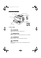
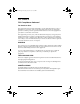
H5pokr4.fm Page ii Tuesday, July 14, 1998 4:39 PM Printer Parts and Labels Paper roll cover Auto-cutter cover Paper roll control panel Front cover POWER ERROR PAPER OUT FEED Slip paper control panel FORWARD On/Off switch REVERSE POWER ERROR RELEASE SLIP RELEASE Caution Labels CAUTION: Thermal head and printer head are hot. ATTENTION: La téte thermique et la téte d’imprimante sont chaudes. VORSICHT: Der Thermalkopf und der Druckerkopf sind heiß.
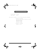
H5pokr4.fm Page iii Tuesday, July 14, 1998 4:39 PM Instruction Labels 2 1 Label affixed on the document table Ribbon installation label inside front cover Label inside paper roll cover Label inside cutter section CAUTION: Caution labels for drawer kick-out and display module connectors.
H5pofr1.fm Page i Tuesday, July 14, 1998 12:35 PM Quick Reference This Quick Reference will direct you to key areas of this Operator’s Manual. For a complete listing of topics, see the Contents. Printer Parts and Labels Ordering Paper and Ribbons inside front cover page viii Where to order paper and ribbons. Setting Up the Printer page 1-1 How to set up the printer. Installing and Replacing Paper page 1-10 How to load or change the roll paper.
H5pofr1.fm Page ii Tuesday, July 14, 1998 12:35 PM All rights reserved. No part of this publication may be reproduced, stored in a retrieval system, or transmitted in any form or by any means, electronic, mechanical, photocopying, recording, or otherwise, without the prior written permission of Seiko Epson Corporation. No patent liability is assumed with respect to the use of the information contained herein.
H5pofr1.fm Page iii Tuesday, July 14, 1998 12:35 PM FCC CLASS A FCC Compliance Statement For American Users This equipment has been tested and found to comply with the limits for a Class A digital device, pursuant to Part 15 of the FCC Rules. These limits are designed to provide reasonable protection against harmful interference when the equipment is operated in a commercial environment.
H5pofr1.
H5pofr1.fm Page v Tuesday, July 14, 1998 12:35 PM EMI and Safety Standards Applied The following standards are applied only to the printers that are so labeled.
H5pofr1.fm Page vi Tuesday, July 14, 1998 12:35 PM About This Manual Setting Up and Using ❏ Chapter 1 contains information on unpacking the printer, setting it up, setting the DIP switches, and adjusting the paper near end sensor. ❏ Chapter 2 contains information on using the printer. ❏ Chapter 3 contains troubleshooting information.
H5poir1.fm Page vii Tuesday, July 14, 1998 12:36 PM Introduction Features The TM-H5000II and TM-H5000IIP are high-quality POS printers that can print on slip and receipt paper (paper roll). The printers have the following features: Slip Section ❏ Wide slip paper capability (maximum characters per line: 88 with 7 × 9 font). ❏ Copy printing is possible. ❏ High throughput using bidirectional, minimum distance printing.
H5poir1.
H5poir1.fm Page ix Tuesday, July 14, 1998 12:36 PM Tel: (510) 782-0197 Fax: (510) 782-7124 In Europe: Nakagawa Mfg (Europe) GmbH. Krützpoort 16, 47804 Krefeld, Germany Tel: 02151-711051 Fax: 02151-713293 In Southeast Asia: N.A.K. Mfg (Malaysia) SDN BHD Lot 19-11, Bersatu Industrial Complexs, Jalan Satu, Kaw Per. Cheras Jaya,. Balakong Industrial Area, 43200 Cheras.
H5poir1.fm Page x Tuesday, July 14, 1998 12:36 PM Original paper: AF50KS-E Jujo Thermal Oy (Finland) P.O. Box 92 FIN27501 Kauttua Finland Tel: 38-3932900 Fax: 38-3932419 Original paper: P350(F380) Kanzaki Specialty Papers, Inc. 1500 Main Street Spring field, MA 01115 U.S.A. Tel: (413) 736-3216 Fax: (413) 734-5101 Ordering Ribbon Cassettes The TM-H5000II series printer uses a long-lasting ribbon cassette in the slip section. To order ribbon cassettes, contact your dealer or your local affiliate.
H5potr2.fm Page xi Tuesday, July 14, 1998 12:37 PM Contents Quick Reference. . . . . . . . . . . . . . . . . . . . . . . . . . . . . . . . . . . . . . . . . . . . . . . . . . . . . . . . i Introduction . . . . . . . . . . . . . . . . . . . . . . . . . . . . . . . . . . . . . . . . . . . . . . . . . . . . . . . . . . . vii Chapter 1 Setting Up the Printer Unpacking . . . . . . . . . . . . . . . . . . . . . . . . . . . . . . . . . . . . . . . . . . . . . . . . . . . . . . . . . . . .
H5potr2.fm Page xii Tuesday, July 14, 1998 12:37 PM Chapter 4 Reference Information Printing Specifications . . . . . . . . . . . . . . . . . . . . . . . . . . . . . . . . . . . . . . . . . . . . . . . . . . 4-1 Slip Paper . . . . . . . . . . . . . . . . . . . . . . . . . . . . . . . . . . . . . . . . . . . . . . . . . . . . . . . . . 4-1 Receipt Paper . . . . . . . . . . . . . . . . . . . . . . . . . . . . . . . . . . . . . . . . . . . . . . . . . . . . . 4-2 Ribbon Specifications . . . . . . . . . . . .
Chapter 1 Setting Up the Printer Unpacking Your printer box should include these items. If any items are damaged or missing, please contact your dealer for assistance. Ribbon Paper roll Hexagonal lock screws These screws are used only for the serial interface (They are not always included.) Switch cover See the note on page 1-4 for information about the hexagonal lock screws. Note: When you lift the printer, be sure to hold the bottom of the printer to prevent damage.
H5po1r3.fm Page 2 Tuesday, July 14, 1998 12:31 PM Removing the protective material 1. Open the printer by pulling up on the tab on the front cover. Tab 2. Remove the two dampers from the printer as shown below. 3. Store the dampers with the other packing materials and use them when transporting your printer.
H5po1r3.fm Page 3 Tuesday, July 14, 1998 12:31 PM Connecting the Cables and Grounding the Printer You can connect up to five cables to the printer. They all connect to the connector panel on the bottom of the printer, which is shown below: Grounding screw Power supply Drawer kick-out (See note below) Display module Interface Note: There are caution labels beside the drawer kick-out connector and the display module connector.
H5po1r3.fm Page 4 Tuesday, July 14, 1998 12:31 PM 2. Tighten the screws on both sides of the cable connector. Note: Your printer has inch-type hexagonal lock screws installed. If your interface cable requires millimeter-type screws, replace the inch-type screws with the enclosed millimeter-type screws using a hex screwdriver (5 mm). Inch screw Millimeter screw 3. Attach the other end of the cable to the computer.
H5po1r3.fm Page 5 Tuesday, July 14, 1998 12:31 PM Connecting the Drawer WARNING: Use a drawer that matches the printer specification. Using an improper drawer may damage the drawer as well as the printer. CAUTION: Do not connect a telephone line to the drawer kick-out connector; otherwise the printer and the telephone line may be damaged. Plug the drawer cable into the drawer kick-out connector on the bottom of the printer next to the power supply connector.
H5po1r3.fm Page 6 Tuesday, July 14, 1998 12:31 PM Anschließen der Lade WARNUNG: Eine für den Drucker geeignete Lade verwenden. Bei Verwendung einer falschen Lade kann diese oder der Drucker beschädigt werden. ACHTUNG: Kein Telefonkabel an die Schnappsteckerbuchse anschließen, da sonst der Drucker und die Telefonkabel beschädigt werden können. Das Kabel der Lade an die Schnappsteckerbuchse unten am Drucker neben dem Netßzanschluß anschließen.
H5po1r3.fm Page 7 Tuesday, July 14, 1998 12:31 PM Connecting the Display Module The display module connector of the printer can be used only for the serial interface. Plug the cable connector (provided with the direct connection display module) securely into the printer’s display module connector until it clicks. CAUTION: Be sure not to connect this cable to the drawer kick-out connector, which is to the left of the power supply connector. Do not connect a telephone line to the display connector.
H5po1r3.fm Page 8 Tuesday, July 14, 1998 12:31 PM 2. Connect the ground wire to the printer using the FG screw on the bottom of the printer, as shown. Connecting the Power Supply Use the optional EPSON PS-170 or equivalent power supply for your printer. WARNING: Make sure that you use the EPSON PS-170 power supply or equivalent. Using an incorrect power supply may cause fire or electrical shock.
H5po1r3.fm Page 9 Tuesday, July 14, 1998 12:31 PM CAUTIONS: When connecting or disconnecting the power supply from the printer, make sure that the power supply is not plugged into an electrical outlet. Otherwise you may damage the power supply or the printer. If the power supply’s rated voltage and your outlet’s voltage do not match, contact your dealer for assistance. Do not plug in the power cord. Otherwise you may damage the power supply or the printer. 1.
H5po1r3.fm Page 10 Tuesday, July 14, 1998 12:31 PM Installing or Replacing the Paper Roll Note: Be sure to use paper rolls that meet the specifications. Do not use paper rolls that have the paper glued to the core because the printer cannot detect the paper end correctly. 1. Make sure that the printer is not receiving data; otherwise, data may be lost. 2. Open the paper roll cover by pressing the cover-open button. If the cover-open button will not open the cover, see page 3-4 in Troubleshooting. 3.
H5po1r3.fm Page 11 Tuesday, July 14, 1998 12:31 PM 4. Insert the paper roll as shown. 5. Be sure to note the correct direction that the paper comes off the roll.
H5po1r3.fm Page 12 Tuesday, July 14, 1998 12:31 PM 6. Pull out a small amount of paper, as shown. Then close the cover. 7. Tear off the paper as shown.
H5po1r3.fm Page 13 Tuesday, July 14, 1998 12:31 PM Installing the Ribbon Cassette Use the EPSON ERC-31(P) ribbon cassette for your printer. Note the label inside this section that can assist you in replacing the ribbon. CAUTION: Never turn the ribbon knob in the opposite direction of the arrow marked on the cassette; otherwise the ribbon cassette may be damaged. 1. Be sure the printer is not receiving data when you replace a ribbon cassette; otherwise data may be lost. 2.
H5po1r3.fm Page 14 Tuesday, July 14, 1998 12:31 PM 4. If you are replacing a used ribbon, grasp the end of the tab and remove it from the printer. See the illustration in step 5 for the location of the tab. 5. Turn the ribbon knob two or three times in the direction of the arrow to take up any slack in the ribbon. Tab 6. Insert the ribbon cassette in the printer and rotate the cassette's knob two or three more times. This is necessary to place the ribbon in the correct position.
Using the Power Switch Cover WARNING: If an accident occurs when the power switch cover is attached, unplug the power supply cord from the outlet immediately. Continued usage may lead to fire or shock. You can use the enclosed power switch cover to make sure that the power switch is not accidentally pressed. If you want to use this cover, install it as shown in the illustration below. Self Test The self test lets you know if your printer is operating properly.
H5po1r3.fm Page 16 Tuesday, July 14, 1998 12:31 PM 2. While holding down the FEED button, turn on the printer using the switch on the front of the printer to begin the self test. The self test prints the printer settings and then prints the following, cuts the paper, and pauses. (The PAPER OUT light blinks.) Self test printing. Please press the PAPER FEED button. 3. Press the FEED button to continue printing. The printer prints a pattern using the built-in character set. 4.
H5po1r3.fm Page 17 Tuesday, July 14, 1998 12:31 PM 4. Remove the paper from the printer and feed another sheet of slip paper into the printer to print characters from the character table. Continue to feed slip paper into the printer until the self test prints the following: ***completed*** The printer is ready to receive data as soon as it completes the self test. Note: If you want to pause the self test manually, press the REVERSE button. Press the REVERSE button again to continue the self test.
H5po2r11.fm Page 1 Tuesday, July 14, 1998 12:32 PM Chapter 2 Using the Printer Operating the Control Panels You can control the basic paper feeding operations of the printer with the buttons on the control panels. The indicator lights help you monitor the printer’s status. Paper Roll Control Panel POWER ERROR PAPER OUT FEED Button The button can be disabled by the ESC c 5 command, but it works whenever the printer cover is open, even if it has been disabled by the ESC c 5 command.
H5po2r11.fm Page 2 Tuesday, July 14, 1998 12:32 PM Buttons The printer and these buttons will not operate when the cover is open. Also these buttons can be disabled with the ESC c 5 command. FORWARD When the printer is in the slip mode (the SLIP light is on or blinking), press the FORWARD button once to advance slip paper one line. You can also hold down this button to feed slip paper continuously.
H5po2r11.fm Page 3 Tuesday, July 14, 1998 12:32 PM Slip panel lights POWER The POWER light is on when the printer is on. ERROR This indicates an error in the slip section of the printer. See Chapter 3 for information on what to do when this light comes on. RELEASE This light indicates that platen and paper feed roller are released so that slip paper can be inserted. SLIP This light indicates that the printer is in the slip mode.
H5po2r11.fm Page 4 Tuesday, July 14, 1998 12:32 PM 2. When the SLIP light blinks, insert the slip paper into the slip paper inlet using the right edge of the slip paper inlet as a guide. (Follow steps ➀ and ➁ in the illustration.) 1 2 Note: There is a label on the document table to assist you how to insert slip paper. 3. Make sure you insert the slip paper into the inlet as far as it will go. 4.
H5po2r11.fm Page 5 Tuesday, July 14, 1998 12:32 PM Using the MICR Reader (Option) If your printer has the factory installed optional Magnetic Ink Character Recognition (MICR) reader that enables the printer to read and process MICR characters on personal checks, read this section. Reading MICR characters on personal checks To use the MICR function with personal checks, follow the steps below: CAUTION: Do not insert checks with staples in them.
H5po2r11.fm Page 6 Tuesday, July 14, 1998 12:32 PM 2. Turn the check over so that it is face down with the MICR characters on the right-hand side. The MICR characters must be next to the right edge of the paper inlet. 3. Insert the check straight into the paper inlet, using the right edge of the paper inlet as a guide. 4. Insert the check as far as it will go. The printer will detect the check and start drawing it in. 5. When the printer starts drawing it in, let go of the check immediately.
H5po3r1.fm Page 1 Tuesday, July 14, 1998 12:33 PM Chapter 3 Troubleshooting Troubleshooting This chapter gives solutions to some printer problems you may have. General problems The lights on the control panel do not come on. Make sure that the power supply cables are correctly plugged into the printer, the power unit, and to the power outlet. Make sure that power is supplied to the power outlet. If the outlet is controlled by a switch or timer, use another outlet.
H5po3r1.fm Page 2 Tuesday, July 14, 1998 12:33 PM If there is no paper jam and the printer has been printing for quite a while, the print head may be overheated. If the print head is overheated, the printer will resume printing when the head has cooled (usually within two or three minutes). If there is no paper jam and the print head is not overheated, turn off the printer and turn it back on after about 10 seconds. If the ERROR light is still flashing, contact a qualified service person.
H5po3r1.fm Page 3 Tuesday, July 14, 1998 12:33 PM Paper roll printing is poor. Paper dust on the heating element of the thermal print head can lower the print quality. Try cleaning the print head as described below: Cleaning the paper roll print head CAUTIONS: After printing, the print head can be very hot. Be careful not to touch it. Also let it cool before you clean it. Do not damage the print head by touching it with your fingers or any hard object. 1. Open the paper roll cover. 2.
H5po3r1.fm Page 4 Tuesday, July 14, 1998 12:33 PM A line of dots is missing in the printout. The print head may be damaged. Stop printing and contact your dealer or a qualified service person. Paper handling problems Paper is jammed inside the printer. CAUTIONS: Do not touch the print head because it can be very hot after printing continuously for a long time. Do not move the print head carriage for the slip section. To clear a paper jam, follow the steps below: 1.
H5po3r1.fm Page 5 Tuesday, July 14, 1998 12:33 PM 3. If paper is caught in the automatic cutter in the receipt section and the paper roll cover cannot be opened, open the cutter cover as shown below. 4. Then turn the knob until you see in the opening, as shown in the illustration below. This returns the cutter blade to the normal position. Also notice that there is a label near the cutter to assist you. 5. Close the cutter cover. 6. Open the paper roll cover. 7. Remove the jammed paper.
H5po3r1.fm Page 6 Tuesday, July 14, 1998 12:33 PM Auto cutter problems The auto cutter is jammed. If a foreign object such as a push pin or paper clip drops in the auto cutter and causes the auto cutter to lock up, the printer enters an error state and begins the recovery operation automatically. If the problem is not serious, the auto cutter returns to its normal position without any intervention by the user.
H5po3r1.fm Page 7 Tuesday, July 14, 1998 12:33 PM 2. Following the instructions on the label, rotate the knob until the appears in the hole. 3. Close the cutter cover. Cleaning the Optional MICR Mechanism MICR cleaning (when the printer is used with a MICR reader) Use a moistened cleaning sheet for the MICR head. Use an adhesive cleaning sheet for the MICR feed roller. See the table below for cleaning frequency.
H5po3r1.fm Page 8 Tuesday, July 14, 1998 12:33 PM Moistened cleaning sheet Use the following or an equivalent commercially available cleaning sheet: PRESAT brand (KIC) "CHECK READER CLEANING CARD." Adhesive cleaning sheet A cleaning sheet is available from EPSON. Part name: Sheet-roller cleaning-A Part number: 1038046 Adhesive cleaning Cleaning procedure You can perform cleaning either in self mode or command mode. These modes are described below.
H5po3r1.fm Page 9 Tuesday, July 14, 1998 12:33 PM Self mode 1. Load paper roll into the printer. 2. Turn off the power. 3. Open the front cover. 4. Turn the power back on while holding down the RELEASE button. 5. Press the RELEASE button four times. 6. Close the front cover. 7. The printer prints the following message on receipt paper and the SLIP LED flashes. 8. If you are using the adhesive cleaning sheet, remove the tape, as shown below.
H5po3r1.fm Page 10 Tuesday, July 14, 1998 12:33 PM 9. Load the cleaning sheet like a standard check. If you are using the adhesive cleaning sheet, insert the printed (adhesive) side up. CAUTION: Be sure the printed (adhesive) side is up, and the sheet is inserted in the right direction. 10. When the sheet is ejected, press the RELEASE button, and remove the sheet from the printer. CAUTION: Do not use a cleaning sheet more than once. Command mode 1. Send the FS s cleaning command to the printer. 2.
H5po3r1.fm Page 11 Tuesday, July 14, 1998 12:33 PM 4. Run any software program that sends data to the printer. The printer prints “Hexadecimal Dump” and then all the codes it receives in a two-column format. The first column contains the hexadecimal codes and the second column gives the ASCII characters that correspond to the codes. Hexadecimal Dump 1B 21 00 1B 26 02 40 40 . ! . . & . @ @ 1B 25 01 1B 63 34 00 1B . % . . c4 . . 41 42 43 44 45 46 47 48 ABCDEFGH ❏ A period (.
H5po4r3.fm Page 1 Tuesday, July 14, 1998 12:33 PM Chapter 4 Reference Information Printing Specifications Slip Paper Printing method: Serial impact dot matrix Head wire configuration: 9-pin vertical line, 0.353 mm (1/72-inch) wire pitch Head wire diameter: 0.29 mm (.
H5po4r3.fm Page 2 Tuesday, July 14, 1998 12:33 PM Receipt Paper Printing method: Thermal line printing Dot density: 180 dpi × 180 dpi [the number of dots per 25.4 mm (1”)] Printing direction: Unidirectional with friction feed Printing width: 72 mm (2.83”), 512 dot positions Characters per line: 42 (Font A) (default) 56 (Font B) Character spacing: 0.28 mm (.01”) (2 dots) (Font A)(default) 0.28 mm (.01”) (2 dots) (Font B) Programmable by control command. Printing speed High speed mode: 28.
H5po4r3.fm Page 3 Tuesday, July 14, 1998 12:33 PM Approximately 120 mm/second (approximately 4.72”/second) continuous feeding Paper feeding speed: Line spacing (default): 4.23 mm (1/6”) Programmable by control command.
H5po4r3.fm Page 4 Tuesday, July 14, 1998 12:33 PM Ribbon Specifications Type: Exclusive cassette ribbon Ribbon cassette specifications: Part number: ERC-31 (P) Color: (P) Purple Ribbon life: (P) 7,000,000 characters (when 1 character=18 dots) MICR Reader (Option) The MICR reader is a factory-installed option.
H5po4r3.fm Page 5 Tuesday, July 14, 1998 12:33 PM Paper Specifications Paper roll (single-ply): Size: Slip paper: Ambient temperature and copy capability Width: 79.5 mm ± 0.5 mm (3.13” ± 0.02”) Maximum outside diameter: 83 mm (3.27”) Paper roll spool diameter: Inside: 12 mm (0.47”) Outside: 18 mm (0.71”) Paper must not be pasted to the paper roll spool. Take up paper roll width: 80± 0.5 1.0 mm 3.15”± Paper type: Normal paper; Carbon copy paper; Pressure sensitive paper Total thickness: 0.
H5po4r3.fm Page 6 Tuesday, July 14, 1998 12:33 PM Copy capability and paper thickness: Normal paper (single-ply): 0.09 to 0.2 mm (.0035 to .0079”) Carbon copy paper combination: 5 sheets maximum (original + 4 copies) at 20° to 45°C (68° to 113°F) Backing paper: 0.06 to 0.15 mm (.0023 to .0059”) Copy and original: 0.04 to 0.07 mm (.0015 to .0028”) Carbon paper: Approximately 0.035 mm (.0014”) Total thickness: 0.30 mm (.
H5po4r3.fm Page 7 Tuesday, July 14, 1998 12:33 PM Notes on slip paper ❏ The slip paper must be flat, without curls or wrinkles, especially at the top edges. Otherwise, the paper may rub against the ribbon and become dirty. ❏ There must be no glue on the bottom edge. Choose slip paper carefully since paper feeding and insertion are affected by gluing conditions (such as glue quality, method, and length) and glue location (see the illustration below).
H5po4r3.fm Page 8 Tuesday, July 14, 1998 12:33 PM ❏ Since the TOF sensor uses a reflective photo sensor and it detects from the back of slip paper, do not use paper that has holes or dark portions with low reflection (less than 40% reflection) at the sensor position. 31 8 Form stopper position 18.9 MICR head 1.8 1.3 TOF sensor position 38.5 18 39 37.2 Center of the print head Slip feeding roller position 21.9 Slip side guide Paper feed direction BOF sensor 3.
H5po4r3.fm Page 9 Tuesday, July 14, 1998 4:44 PM Electrical Characteristics Supply voltage: +24 VDC ± 10% (optional power supply: EPSON PS-170) Ripple voltage: Current ❏ consumption: (at Operating: Slip 24V, except for drawer kick-out driving) ❏ Operating: Receipt 300mVpp or less (only when the printer is used with the MICR reader). Mean: approximately 1.9A (character font A α-N all columns printing) Peak: approximately 8.0A (20 msec) When the print platen is released: 2.
H5po4r3.fm Page 10 Tuesday, July 14, 1998 12:33 PM Reliability Slip: Mechanism: Life (when printing alphanumeric characters): Print head: 200 million characters (when printing with font B) MICR reader mechanism (only when the printer is used with the MICR reader): End of life is defined to have reached the end of its life when it reaches the beginning of the Wearout Period. 240,000 passes MTBF: 180,000 hours Failure is defined as Random Failure occurring at the time of the Random Failure Period.
H5po4r3.
H5poar2.fm Page 1 Tuesday, July 14, 1998 12:34 PM Appendix A Dip Switch and Paper Near End Settings Although the factory settings are best for almost all uses, if you have special requirements, you can change the DIP switch or paper near end settings. Setting the DIP Switches DIP switch functions Your printer has two sets of DIP switches. The functions of the switches are shown in the following tables.
H5poar2.
H5poar2.fm Page 3 Tuesday, July 14, 1998 12:34 PM Notes: • When pin 6 of the interface connector is used for the reset signal, the printer is reset at MARK on the RS-232 level. • When pin 25 of the interface connector is used for the reset signal, the printer is reset at SPACE on the RS-232 level or at HIGH on the TTL level.
H5poar2.
H5poar2.fm Page 5 Tuesday, July 14, 1998 12:34 PM Print Density and Low power consumption mode selection (Only for Receipt) Print Density SW 2-3 SW 2-4 ON ON 1 (Light) OFF OFF 2 ON OFF 3 (Dark) OFF ON Low power consumption mode Notes: • When pin 6 of the interface connector is used for the reset signal, the printer is reset at MARK on the RS-232 level.
H5poar2.fm Page 6 Tuesday, July 14, 1998 12:34 PM Changing the DIP switch settings If you need to change settings, follow the steps below to make your changes: CAUTION: Turn off the printer while removing the DIP switch cover to prevent an electric short, which can damage the printer. 1. Make sure the printer is turned off. 2. Remove the screw from the DIP switch cover. Then take off the DIP switch cover, as shown in the illustration below. DSW1 DSW2 3.
H5poar2.fm Page 7 Tuesday, July 14, 1998 12:34 PM Adjusting the Paper Near End Sensor The paper near end sensor detects when paper is almost gone by measuring the diameter of the paper roll. The sensor has two settings. Because of variations in paper roll cores, it is not possible for the sensor to measure exactly the length of paper left on the roll when the sensor is triggered. Of the two settings, the factory setting (lower) leaves the least amount of paper on the roll when the sensor is triggered.
Appendix B EPSON Sales Subsidiaries EPSON AMERICA INC./OEM DIV. 20770 Madrona Ave. Torrance, CA 90559-2842 U.S.A. Tel : 1-310-787-6300 Fax : 1-310-782-5350 EPSON EUROPE B.V. Prof. J.H. Bavincklaan 5 1183 AT Amstelveen The Netherlands Tel : 31-(0)20-5475-251 Fax : 31-(0)20-6454-315 EPSON Deutschland GmbH Zülpicher Strasse 6, 40549 Düsseldorf 11, Germany Tel : 49-(0)211-5603152 Fax : 49-(0)211-5603319 EPSON U.K. LIMITED Campus 100 Maylands Ave. Hemel Hempstead Herts.
EPSON HONG KONG LIMITED 25/F., Harbor Centre, 25, Harbor Road, Wanchai, Hong Kong Tel : 852-2-585-4663 Fax : 852-2-827-4346 EPSON TAIWAN TECHNOLOGY & TRADING LTD. 10f, No. 287, Nanking E. Road, Sec. 3 Taipei, Taiwan R.O.C. Tel : 886-(0)2-717-7360 Fax : 886-(0)2-718-9366 SEIKO EPSON CORP. KOREA OFFICE 10F, KIL 63 Building 60, Yoido Dong, Youngedungpo-Ku, Seoul, Korea Tel : 82-(0)2-784-6027 Fax : 82-(0)2-769-1049 EPSON AUSTRALIA PTY. LTD.