SERVICE MANUAL A4 Full Color Laser Printer EPSON AcuLaser C1100 SEPG04002
Notice: All rights reserved. No part of this manual may be reproduced, stored in a retrieval system, or transmitted in any form or by any means, electronic, mechanical, photocopying, recording, or otherwise, without the prior written permission of SEIKO EPSON CORPORATION. The contents of this manual are subject to change without notice. All effort have been made to ensure the accuracy of the contents of this manual.
PRECAUTIONS Precautionary notations throughout the text are categorized relative to 1)Personal injury and 2) damage to equipment. DANGER Signals a precaution which, if ignored, could result in serious or fatal personal injury. Great caution should be exercised in performing procedures preceded by DANGER Headings. WARNING Signals a precaution which, if ignored, could result in damage to equipment.
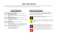
About This Manual This manual describes basic functions, theory of electrical and mechanical operations, maintenance and repair procedures of the printer. The instructions and procedures included herein are intended for the experienced repair technicians, and attention should be given to the precautions on the preceding page. Manual Configuration This manual consists of six chapters and Appendix. CHAPTER 1.PRODUCT DESCRIPTIONS Provides a general overview and specifications of the product. CHAPTER 2.
Abbreviations The following is a representative example of abbreviations (both original and common ones) used in this manual. ADC............... Automatic Density Control AG .................................... Analog Ground APS............................... Auto Paper Select ARC ................. Auto Registration Control ASSY......................................... Assembly ATS.......................... Auto Tray Switching B .......................................................Black BCR ..............
Safety Information To prevent accidents during a maintenance procedure, strictly observe the Warnings and Cautions and never depart from the instructions given in this document. Do not do anything that is dangerous even if not specifically described in this manual. In addition to the descriptions below and those given in this manual, there are many situations and circumstances that could result in serious bodily injury. Always pay enough attention to secure safety when working with the printer.
High Temperature Assembly When working with hot parts (FUSER etc.) make sure to turn the power off, unplug the power cable, and leave the printer until it cools down sufficiently to work with to prevent burn injury. W A R N IN G As the inside of the printer is high-temperature state immediately after the operation, leave it more than 30 minutes before working.
Laser Beam W A R N IN G Letting a laser beam get into your eye directly could result in C H E C K P O IN T loss of vision. Never open the Cover where the Warning Label About Laser Beam is affixed. Before disassembling or assembling, be sure to turn the power off. If you need to work on the printer with power applied, strictly follow the instructions in this manual. Understand hazardous nature of the laser beam, use extreme caution to avoid injury of yourself and anyone around you.
Warning label for Laser Beam Warning/Caution Labels Warning labels and caution labels are attached on the corresponding locations on or in the printer. C H E C K P O IN T The label is attached on the top of the laser beam emitting unit (ROS ASSY) to alert the service personnel the danger of laser beam. In maintenance work, check that the labels are free from peeling and soiling.
Cautions relating to Toner cleaning To prevent ignition, explosion, burn, injury, etc., do not use a general vacuum cleaner for cleaning dropped toner. (To do so may cause the toner to catch fire by sparks in the vacuum cleaner.) W A R N IN G Do not pick up dropped toner with a general vacuum cleaner. To do so may cause ignition.
Safety Devices Use extra care when checking or servicing the safety devices (e.g., interlock switches, fuses, thermostat). The printer's cover, control panel and any other parts which are directly related to the user's safety should also be observed carefully.
Leg_Sec001_025EA Schematic Diagram of Safety System
Revision Status Revision Date of Issue A 28 September, 2004 B 13 JULY, 2005 Description First release Chapter 1: • Table 1-2 Color mode (Unit: seconds or less) (p.23) / Modification • Supported paper size, type and orientation (p.25) / Modification • NOISE (p.29) / Modification • Calibrating Printer (p.57) / Modification • Figure 1-15 Status Sheet (Simplified version) (p.68) / Modification • Print volume (pages/month) (p.33) / Modification • 1.9.
EPSON AcuLaser C1100 Revision B Contents Chapter 1 PRODUCT DESCRIPTION 1.1 Overview ............................................................................................................. 20 1.1.1 Engine features ........................................................................................... 20 1.1.2 Controller features ...................................................................................... 20 1.1.3 Software features ........................................................
EPSON AcuLaser C1100 1.16.4 Warning Messages and Troubleshooting.................................................. 1.16.5 Service Call Error Messages..................................................................... 1.17 Expanding the RAM.......................................................................................... 1.18 Handling Precautions......................................................................................... 1.18.1 Precautions When Turning Off the Power....................
EPSON AcuLaser C1100 Revision B 3.6.2 Printing Procedure of Test Print Pattern................................................... 274 Chapter 4 DISASSEMBLY AND ASSEMBLY 4.1 Overview ........................................................................................................... 4.1.1 Precautions................................................................................................ 4.1.2 Before you start work .............................................................................
EPSON AcuLaser C1100 4.6.8 LATCH ASSY AD ................................................................................... 372 4.6.9 BCR CLN XERO ASSY .......................................................................... 373 4.6.10 SENSOR TNER FULL........................................................................... 374 4.7 ROS ................................................................................................................... 375 4.7.1 ROS ASSY ..................................
EPSON AcuLaser C1100 4.13.14 MOTOR ASSY FEEDER..................................................................... 4.13.15 CLUTCH ASSY FEED ........................................................................ 4.13.16 HARNESS-ASSY FEED 1................................................................... 4.13.17 ROLL ASSY TURN 500...................................................................... 4.13.18 SWITCH FEEDER DOOR................................................................... 4.13.
CHAPTER 1 PRODUCT DESCRIPTION
EPSON AcuLaser C1100 1.1 Overview This printer is a conventional 4-cycle color page printer that takes advantage of laser and electrophotographic technologies. Revision B 1.1.2 Controller features Host-based controller CPU : VR4305 (66.7 MHz) RAM: 32 MB as standard, can be expanded up to 256 MB 1.1.
EPSON AcuLaser C1100 Revision B 1.2 Basic Specifications PRINTING SPEED MODE Color mode (F/C) 1.2.
EPSON AcuLaser C1100 Revision B PRINTING MODE BY PAPER TYPE Table 1-1. Printing mode by paper type Printing speed mode Paper type F/C B/W 64 to (RX-80/4024) Standard Standard Plain paper (Back) For reverse side of paper when feeding manually to print on both sides. Standard Standard Semi-thick paper 81 to 105g/m2 (EPSON High quality Plain paper) Standard Standard Semi-thick paper (Back) For reverse side of paper when feeding manually to print on both sides.
EPSON AcuLaser C1100 Revision B FIRST PRINT TIME CONTINUOUS PRINTING SPEED The time from receiving the Start command to when trailing edge of the paper leaves the paper eject roller. Note that the time given in the tables below does not apply when the printer is in the conditions described in “1.11 Engine Restrictions” (p42). Note that the time given in the tables below does not apply when the printer is in the conditions described in “1.11 Engine Restrictions” (p42). Monochrome mode*1 Table 1-2.
EPSON AcuLaser C1100 Revision B PAPER FEED REFERENCE COMBINATION WITH OPTIONAL CASSETTE Reference position to feed paper (in any size) is always center of the feeders. By attaching the optional 500-sheet cassette, the paper supply capacity can be increased as follows. PAPER FEED Table 1-7. Combination with optional cassette Table 1-6.
EPSON AcuLaser C1100 Revision B SUPPORTED PAPER SIZE, TYPE AND ORIENTATION Table 1-8. List of supported paper size, type and orientation Standard Paper Horizontal (width) MP tray 500-sheet cassette Paper orientation Duplex printing A4 297.00 210.00 { { SEF z A5 148.00 210.00 { --- SEF --- B5 257.00 182.00 { --- SEF z LETTER 279.40 (11.00") 215.90 (8.50") { { SEF z HALF LETTER 215.90 (8.50") 139.70 (5.50") {*1 --- SEF --- GLT 266.70 (10.50") 203.20 (8.
EPSON AcuLaser C1100 Revision B Envelope orientation DIMENSIONS AND WEIGHT Dimensions and weight of each unit Paper feed direction Table 1-9. Dimensions and weight Envelope type Com-10 DL / C6*1 MONARCH*2 C5 / ISO-B5 NOTE 1: Set envelopes with its print surface facing up 2: Image quality and feed is not guaranteed when printing on the back side (flap side) of envelopes.
EPSON AcuLaser C1100 Revision B Dimensions and weight with options installed 510mm Table 1-10. Dimensions and weights with options installed Depth (mm) Height (mm) Weight (k) Main unit + 500-sheet cassette unit 445 460 570 33 Main unit + Duplex unit 445 510 473 29 Main unit + 500-sheet cassette unit + Duplex unit 445 510 604 37 473mm Width (mm) NOTE 1: Manufacturing tolerance is ± 5 mm in dimensions and ± 0.5 kg in weight.
EPSON AcuLaser C1100 Revision B CONSUMABLES AND PERIODIC REPLACEMENT UNIT Table 1-11. List of Consumables and periodic replacement unit Consumables Replacement unit Table 1-12. List of power consumption Toner Cartridge (Black, Cyan, Yellow, Magenta) Photoconductor Unit (with waste toner box and transfer belt) FUSER ASSY Periodic replacement units The maximum rated current and power consumption are measured with all engine options and controller options installed.
EPSON AcuLaser C1100 Revision B NOISE Sound pressure Table 1-13. Sound pressure Printing mode Standby mode Sleep mode 53dB Background noise Background noise Main unit NOTE 1: The method of measuring and calculation conforms to ISO-7779. 2: Values mentioned above are actual measurement value. Sound power Table 1-14. Sound power Printing mode Standby mode Sleep mode 6.4B Background noise Background noise Main unit NOTE 1: The method of measuring and calculation conforms to ISO-7779.
EPSON AcuLaser C1100 Revision B 1.3 Paper Specifications 1.3.2 Paper that may cause printing defects, paper jams or printer malfunction 1.3.
EPSON AcuLaser C1100 Revision B 1.3.3 Available Paper by Feeder 1.3.4 Printing Area Table 1-15. Types of Paper Feed MAXIMUM PRINTABLE AREA Special paper Option Standard Feeder Standard paper Plain paper Transparency Width: 216.00 mm x Length: 297.
EPSON AcuLaser C1100 Revision B 1.4 Reliability and Serviceability NOTE 1: Environmental conditions: Normal operating environment 2: Paper size: Regular size 3: Humidity: Newly unpackaged paper 1.4.1 Reliability 4: Paper type: The 500-sheet cassette does not use special paper MECHANICAL LIFETIME Main unit: Color:Monochrome = 2:1 : 200, 000 pages or 5 years, whichever comes first. Color only : 150, 000 pages or 5 years, whichever comes first.
EPSON AcuLaser C1100 Revision B 1.4.2 Durability SKEW Table 1-18. Skew PRINT VOLUME (PAGES/MONTH) A4 Simplex printing Duplex printing Average : 3, 000 pages/month Main scanning direction (| a-b |) 1.1mm 1.1mm Maximum : 30, 000 pages/month Sub-scanning direction (| c-d |) 1.0mm 1.0mm 1.4.3 Serviceability Table 1-19. Length standard of measurement A4 Simplex printing Duplex printing Main scanning direction (e) 179.8 mm Sub-scanning direction (f) 139.
EPSON AcuLaser C1100 Revision B 1.5 Service Conditions 1.5.5 Space Requirements 1.5.1 Ambient Temperature and Humidity In order to ensure that the printer operates properly, provide at least as much space as shown in the diagram below. Table 1-21. Temperature (ºC) Humidity (%RH) Operating 5 to 32 15 to 85 Non-operating -20 to 40 5 to 85 870mm 100mm Other 280mm 300mm No condensation 700mm 1.5.2 Air Pressure (Altitude) 65 to 101kPa (0 to 3, 100m or less) 1.5.
EPSON AcuLaser C1100 Revision B 1.6 Conditions for Storage and Transport 1.6.4 Vibration There should be no damage under the following conditions 1.6.1 Ambient Temperature and Humidity Table 1-22. Condition Temperature (°C) Normal conditions Harsh conditions Note *1: Humidity*1 0 to 35 (%RH) 35 to 40 High 80 to 95 Low -20 to 0 Low 5 to 15 : 5 to 55 Hz Acceleration : 1.5 G However, between 5 to 10 Hz, constant 7.5 mm double amplitude is assumed.
EPSON AcuLaser C1100 Revision B 1.7 Electrical Characteristics 1.7.4 Inrush Current 1/2 cycle NOTE: The following sections do not include any optional units. 100 A or less (0-peak) : Including heater inrush (Conditions: Above 23 ºC with cold start) 1.7.1 Electrical Fast Transient /Bursts (AC Line Noise) Ensure the following conditions using evaluation methods compliant with IEC610004-4. 1 kV : No errors excluding insignificant dot errors 2 kV : No damage to parts 1.7.
EPSON AcuLaser C1100 Revision B 1.8 Compatible Specification 1.8.4 Power Supply Harmonics JBMIA harmonics control guidelines 1.8.1 Safety Standard 1.8.5 Power Consumption Table 1-25. Safety Standards Model Type Conforms to International Energy Star Program standards Applicable Standards 120 V UL60950 3rd Edition CSA C22.2 No.60950-00 1.8.
EPSON AcuLaser C1100 Revision B 1.9 Consumables/Periodic replacement unit C A U T IO N Note *1: The print page-based service life values of the Consumables and Periodical Replacement Parts are guidelines. The number of printable pages changes depending on how they are printed.
EPSON AcuLaser C1100 Revision B 1.9.2 Conditions for Storage and Transport Temperature and humidity conditions Condition Temperature (°C) Humidity*1 (%RH) Guarantee period 0 to 35 15 to 80 24 months (unopened) Normal conditions Harsh conditions Note *1: High 35 to 40 High 80 to 95 Low -20 to 0 Low 5 to 15 Max. of 1 month Non-condensing Note : Storage time after opening is 12 months in the normal operating environment.
EPSON AcuLaser C1100 Revision B 1.10 External Appearance and Unit Names 1.10.1 Unit names Table 1-30. List of unit names No. Name No. Name No. Name No.
EPSON AcuLaser C1100 Revision B 23 16 17 15 18 22 19 25 24 20 Figure 1-10. Unit name_3 Figure 1-12. Unit name_5 26 1 2 4 5 27 Figure 1-11.
EPSON AcuLaser C1100 Revision B 1.11 Engine Restrictions FACTORS LIMITING PRINTING SPEED Image quality adjustment Table 1-31. Iamge quality adjustment Purpose Condition and control 1. 1 During Printing To keep the image density at target level. 2. When printing more than 51 copies (pages) continuously*1: Every time the printer makes 50 copies (pages), it stops the job temporarily to perform the ADC*2 control.
EPSON AcuLaser C1100 Revision B FACTORS LIMITING PRINTING START Table 1-32. Factors limiting printing start Condition and control Time required (sec) When the number of printed copies (pages) becomes 20 (by both continuous or intermittent printing) after performing the ADC, the printer performs another ADC when the current job is finished. 45 Purpose 1 Cycle Down To keep the image density at target level. 1.
EPSON AcuLaser C1100 Revision B 1.12 Notes When Replacing Consumables and Installing Optional Products 1.12.1 Consumables Toner Cartridge The power supply of the main unit should be on. If the main unit is turned off, the cartridge that needs to be replaced does not move to the cartridge replacement position. Photoconductor Unit This unit can be replaced regardless of whether or not the main unit is turned on. 1.12.2 Optional Products 500-Sheet Cassette Turn off the main unit before installing.
EPSON AcuLaser C1100 Revision B Color mode 1.13 Life details Table 1-34. Color mode Monochrome mode Table 1-33.
EPSON AcuLaser C1100 Revision B Printer mode 1.14 Controller Specifications 1.14.1 Controller Basic Specifications CPU : VR4305 (66.
EPSON AcuLaser C1100 Revision B 1.14.3 External Interface Specifications The printer provides the following host interfaces. Parallel (IEEE1284 compliant) interface: Standard USB (Rev.2.0 HS) interface : Standard Network interface : Standard or Option The locations of the respective interfaces are shown below. USB INTERFACE SPECIFICATIONS Universal Serial Bus Specification Rev.2.0 HS is supported.
EPSON AcuLaser C1100 Revision B 1.15 Control Panel LCD 1 line x 20 characters Data LED (Yellow) 1.15.1 External Appearance and Names Ready LED (Green) “ Error LED (Red) (2)” button Table 1-36. Indicators Indicators LCD Function 1 line x 20 characters (5 x 7 dot matrix) On Ready LED Off : Printer is ready to print. : Printer is not ready to print. Data LED On : Printer contains data that has not been processed yet. Off : Printer has finished processing all print data.
EPSON AcuLaser C1100 Revision B 1.15.2 Panel Settings List Tray Menu The printer settings are listed below. Setting Setting values Status sheet MP Tray Size*1 A4, A5, B5, LT, HLT, GLT, EXE, MON, C10, DL, C5, C6, IB5 { LC Size*2*3 A4, LT, { MP Type*2*3 Plain, SemiThk, Letterhead, Recycled, Color, Trnsprncy, Labels { Plain, SemiThk, Letterhead, Recycled, Color { Underlined value in the Setting value column are factory default settings.
EPSON AcuLaser C1100 Revision B Setup Menu Reset Menu Setting Setting values Status sheet Setting Setting values Lang Lang Sprache LINGUA LENG SPRAK Sprog Taal KIELI Ling. English Francais Deutsch ITALIANO ESPANOL SVENSKA Dansk Nederl.
EPSON AcuLaser C1100 Revision B USB Menu Network Menu Setting USB I/F*1 USB SPEED*1 USB ExtI/Fconfg*2 IP*3*4*5 On, Off { HS, FS { No, Yes --- No, Yes --- Get IPAddress*3*4*7 Panel, Auto, PING { Panel, Auto, PING --- IP*3*5 0.0.0.0 to 192.168.192.168 to 255.255.255.255 { --- SM*3 0.0.0.0 to 255.255.255.0 to 255.255.255.255 { --- GW*3 0.0.0.0 to 255.255.255.255 { --- AppleTalk*3 On, Off { On, Off { On, Off { 0.0.0.0 to 255.255.255.
EPSON AcuLaser C1100 Revision B PRINTER ADJUST MENU Maintenance Menu Setting Value Normal*1 0 ~ 5 ~ 15 SemiThk*1 0 ~ 5 ~ 15 Thick*1 0 ~ 5 ~ 15 ExtraThk*1 0 ~ 5 ~ 15 Card*1 0 ~ 5 ~ 15 Envelope*1 -3.5 to 0.0 to 3.5 mm Scan Offset*2 -3.5 to 0.0 to 3.5 mm Feed Offset2*2 -3.5 to 0.0 to 3.5 mm Scan Offset2*2 -3.5 to 0.0 to 3.
EPSON AcuLaser C1100 Revision B USER SETTING ITEMS OTHER THAN IN THE SETTING MENU The following is a list of user settings not included in the Setup menu. Initialization by the Initialization menu of the Panel does not clear these items.
EPSON AcuLaser C1100 Revision B 1.15.3 Explanation of Menu and Settings Maintenance Menu The following are items specific to this printer. MCU DATA BackUp*1 Backup the data of the engine. "MCU Data BackUp" is displayed until back up processing ends. Reset menu MCU DATA Restore*1 Change Toner C/Change Toner M/Change Toner Y/Change Toner K Used when replacing a Toner Cartridge before toner end occurs.
EPSON AcuLaser C1100 Revision B Maintenance Mode 1.15.4 Special Operations After the printer enters the Maintenance mode, engine process control (Calibrating Printer) is performed after printing since the process control is a cycle process control. LIST OF OPERATING FUNCTIONS The following is a list of the special operating functions supported by this printer. Do not make these functions (except Support mode and panel setting value initialization) available to users. Table 1-38.
EPSON AcuLaser C1100 Revision B 1.16 Printer Status Table 1-39.
EPSON AcuLaser C1100 Revision B Table 1-39. List of Printer Messages Display Sort 1.16.2 Status Messages and Troubleshooting Error LED status Status code (Job processing) Status 1002 (communication to non active I/F port) Status 1012 The following are items specific to this printer.
EPSON AcuLaser C1100 Revision B 1.16.3 Error Messages and Troubleshooting Irregular Density The following are items specific to this printer. Explanation This error occurs when the image density of all 4 colors at the top of page exceeding the upper limit (240%). At this time, engine stops, and picked up paper is remained in the printer.
EPSON AcuLaser C1100 Revision B NonGenuineToner uuuu w w w w Open (w w w w=A, B, C, D, DM, E, F, G) Explanation Explanation A non-genuine Toner Cartridge is installed. The indicated cover is open. Remedy Open cover A, install the right Toner Cartridge. Remedy The printer recovers from the error by closing the cover. The printer recovers from the error when the cover is closed. Press the Start/Stop button. The message will change to “Non Genuine Toner” and enables the user to print.
EPSON AcuLaser C1100 Revision B Manual Feed ssss Print Overrun Explanation Explanation Manual feed mode is specified for the current print job. During printing in the manual feed mode, the paper ran out. While printing with a flying start, the data does not arrive in time. Remedy Remedy Press the Start/Stop button, the error is canceled, and the page is reprinted Press the Start/Stop button. Printing starts feeding paper from the higher without flying start. priority feeder.
EPSON AcuLaser C1100 Revision B Invalid N/W Module Remove Photocondctr Explanation Explanation The network program does not exist, or a network program that is not for this printer is written. The interfaces maintain the status before the error. This occurs when Photoconductor Unit is installed before all the Toner Cartridges are installed when setting up the printer. This error is provided to make sure that the covers (packing materials) of HOUSING ASSY-DEVEs are removed.
EPSON AcuLaser C1100 Revision B 1.16.4 Warning Messages and Troubleshooting Worn uuuu Dev Unit The following are items specific to this printer. Explanation The HOUSING ASSY-DEVE of each color (C, M, Y, K) reaches the almost end of its life (the rest of the life is about 1000 pages) It is still able to use, however, it is recommended to replace it with a new one. Worn Fuser Explanation The FUSER ASSY comes to near end of its life. The print quality is not guaranteed from now on.
EPSON AcuLaser C1100 Revision B 1.16.5 Service Call Error Messages CONTROLLER-RELATED SERVICE CALL ERRORS This section shows the service call error message of this printer. (For details, refer to Chapter3 “TROUBLESHOOTING”.) Table 1-41. List of Service Call Errors (Controller Related) Internal error code ENGINE-RELATED SERVICE CALL ERRORS Table 1-40.
EPSON AcuLaser C1100 Revision B Table 1-41.
EPSON AcuLaser C1100 Revision B 1.17 Expanding the RAM When the memory is insufficient, the printer displays the following error messages. Mem Overflow Duplex Mem Overflow Image Optimum The following methods can be used to clear the errors. To ensure a stable operation, add more memory. Set the resolution to 300 dpi. In color printing, change the compression format to lossy compression. Set unused interfaces to “Not Use”.
EPSON AcuLaser C1100 Revision B 1.18 Handling Precautions 1.18.1 Precautions When Turning Off the Power This printer includes internal, nonvolatile memory (EEPROM), which stores setting values important to operate the printer normally.
EPSON AcuLaser C1100 Revision B e n space 1.19 Status Sheet There are two kinds of status sheet, the Status Sheet (Simplified version) and the Status Sheet. : ECP : Nibble : Compatibility 11. Number of occurrences of jams indicated by JC and 6 figures Status Sheet (Simplified version): This can be printed using the printer operation panel. And also a Status Sheet on which has no setting information printed by the printer driver is called “Simplified version”.
EPSON AcuLaser C1100 Revision B HARDWARE ENVIRONMENT EXCEPT FOR OPTION 1. Serial No. : Serial number of the unit 2. Firmware Revision : 211XX is indicated. CONSUMABLE INFORMATION AND PART NUMBER Name Part Numbers Toner Cartridge (Cyan) S050193/S050189 Toner Cartridge (Magenta) S050192/S050188 Toner Cartridge (Yellow) S050191/S050187 Toner Cartridge (Black) -/S050190 Photoconductor Unit S051104 NOTE: The first one is the part number of 1.5K, and the latter one is that of 4K. Figure 1-15.
EPSON AcuLaser C1100 Revision B Information Toner Cartridge Cyan Toner Cartridge Magenta Toner Cartridge Yellow Toner Cartridge Black Photoconductor Unit Total Pages Color Pages B/W Pages Needed Soon Needed Soon Needed Soon Needed Soon Needed Soon E E E E E 99999999 99999999 99999999 F F F F F Part Numbers 0193/0189 0192/0188 0191/0187 0190 1104 Tray Menu MP Tray Size LC Size MP Type LC Type Auto A4 Plain Plain Setup Menu Lang MP Mode Size Ignore Auto Cont LCD Contrast English Normal Off Off 7 Pa
EPSON AcuLaser C1100 Revision B 1.20 Engine Status Sheet C A U T IO N Do not disclose this information to the user. It can be output from the Maintenance Menu. For details, refer to Chapter6 “MAINTENANCE” for the Engine Status Sheet.
EPSON AcuLaser C1100 Revision B 1.21 Recommended Operating Environment (Host PC) Minimum requirements for Windows OS : Windows® 95/98/Me/2000/XP, Windows NT® 4.0 CPU : Pentium® II 233 MHz or more (450 MHz or more recommended) RAM : 64 MB or more (128 MB or more recommended) HDD : 500 MB or more space * It is recommended to use the computer with higher than the hardware requirements of the OS. Minimum requirements for Macintosh OS : Mac OS 9x/Mac OSX 10.
EPSON AcuLaser C1100 Revision B 1.22 Paper Handling Algorithm The relationship between paper type, type and size is shown below . Table 1-42.
EPSON AcuLaser C1100 Revision B Table 1-43. CM 1 CM Media Type MP or LC1-3 Type*1 DUPLEX CM Plain, SemiThk, Letterhead, Recycled Color, Labels Standard paper Trnsprnc OHP Option 1 — Option 1 Option 2 — Option 2 Off Note *1: Table 1-46. Duplex Page Size A4, B5, LT, EXE Paper Type Auto duplex Normal SemiThk Effective Note : Duplex printing is not possible with paper other than the above. Paper Type in Selectype for each paper feeder Table 1-44.
CHAPTER 2 OPERATING PRINCIPLES
EPSON AcuLaser C1100 Revision B 2.1 Print Process 2.1.1 Print Process Overview This printer is a “full color laser printer” that uses the principle of electrophotographic recording. The printer contains a drum that forms toner images by four colors of toner “Yellow, Magenta, Cyan and Black (simply called YMCK from here on).” The toner image of each color is formed on the drum, and the toner images formed on the drum is transferred to the Belt (secondary transfer roller).
EPSON AcuLaser C1100 Revision B 2.1.2 Print Process Diagram The diagram below illustrates the entire print process. Leg_Sec06_002EB Figure 2-2.
EPSON AcuLaser C1100 Revision B 2.1.3 Technical Explanation of Print Process 2.1.3.1 Charging At the “Charging” process, BCR (Bias Charge Roll) applies a uniform negative potential to the drum which rotates at a fixed speed. BCR keeps contact with the drum and moves together with it. BCR is a conductive roller, that is negatively charged by HVPS, applies a negative charge to the drum. The drum surface is uniformly charged to a negative potential with DC bias voltage.
EPSON AcuLaser C1100 Revision B 2.1.3.2 Exposure At the “Exposure” process, a laser beam is applied to the negatively charged surface of the drum to form an invisible electrostatic latent image onto the drum. The laser beam is emitted from a laser diode in the ROS ASSY, and directed by the polygon mirror, fixed mirror and lens of the Scanner Assy in the ROS ASSY. A single laser beam is output from the laser diode.
EPSON AcuLaser C1100 Revision B 2.1.3.3 Developing At the “Developing” process, toner is electrically applied to the invisible electrostatic latent image on the drum, to form a visivle image on it. This printer uses two developing systems: a “rotary developing system” that successively rotates four Developer Assys, and a “trickle developing system” that uses developers composed of two components, a carrier and toner.
EPSON AcuLaser C1100 Revision B Toner in the Developer Assy is consumed as the number of prints increases. To The charging characteristics of the carrier is depleted due to dirt caused by the maintain the appropriate development density, the equivalent amount of consumed toner must be replenished to the Developer Assy from the Toner Cartridge. This replenishment is called “toner dispense.” Two types of control (“PCDC” and “ADC”) are used in combination for toner dispense.
EPSON AcuLaser C1100 Revision B 2.1.3.4 Primary transfer (Drum→Belt) At the “Primary transfer” process, the toner image formed on the drum surface is transferred to the Belt surface in Photoconductor Unit by 1st BTR (First Bias Transfer Roll). The 1st BTR is a conductive roller, and is positively charged by the HVPS. The 1st BTR contacts the back side of the Belt and charge the back side to positive.
EPSON AcuLaser C1100 Revision B 2.1.3.5 Cleaning (drum) At the “Cleaning (drum)” process, residual toner is removed from the drum surface. Cleaning the drum Toner that was not transferred to the Belt at the “Primary transfer” process remains on the drum surface. Since the remaining toner hinder subsequent processes, it is scraped off by a Cleaning Blade that contacts with the drum, and is collected in the Waste Toner Box. Figure 2-10.
EPSON AcuLaser C1100 Revision B 2.1.3.6 Repeat (formation of complete toner image) At the “Repeat (formation of complete toner image)” process, the toner images of each color formed on the drum surface are successively transferred to the Belt to form a complete toner image composed of the four colors on the Belt surface. Figure 2-11. Repeat (1) Figure 2-12.
EPSON AcuLaser C1100 Revision B 2.1.3.7 Secondary transfer (Belt→Paper) At the “Secondary transfer” process, the complete toner image formed on the Belt surface is transferred to paper by the 2nd BTR (Second Bias Transfer Roll). The 2nd BTR comes in contact with the Belt only when transferring the image to paper to prevent the toner image formed on the Belt surface from being destroyed. Normally, the 2nd BTR is located at its home position where is detected by the 2nd BTR Retract Sensor.
EPSON AcuLaser C1100 Revision B 2.1.3.8 Discharging 2.1.3.10 Fusing At the “Discharging” process, the charge on the paper is neutralized/removed by the Detack Saw. At the “Fusing” process, toner is fixed on paper with heat and pressure. The Detack Saw contacts the back side of the paper. The charge created at the Fuser Assy does not have a pressure roll, but has a Fuser Belt instead. By MOT ASSY FSR drive, Heat Roll rotates and Fuser Belt is driven by the friction.
EPSON AcuLaser C1100 Revision B 2.2 Flow of Print Data 2.2.1 Data Flow Print data (electric signals) from the Printer Controller follows the flow shown below to become a print image. Formation of 2-D print image: One line of the dot image is formed by turning the laser beam from the laser diode ON and OFF in accordance with the electric signals (VIDEO signal: expresses the image data by voltage levels) from the printer controller.
EPSON AcuLaser C1100 Revision B 2.3 Drive Transmission Path CLUTCH ASSY FEED GEAR FEED 2.3.1 DRIVE ASSY FEED Rotation of DRIVE ASSY FEED is transmitted as follows: DRIVE ASSY FEED CLUTCH ASSY FEED GEAR FEED DRIVE ASSY FEED FRONT Leg_Sec06_042EB ROLL ASSY TURN 500 ROLL ASSY FEED 500 Figure 2-20. Diagram of Drive Transmission Path 500 FEEDER ASSY Leg_Sec06_035EB Figure 2-19.
EPSON AcuLaser C1100 Revision B 2.3.2 MOTOR ASSY P/R, DRIVE ASSY PRO Rotation of MOTOR ASSY P/R and DRIVE ASSY PRO is transmitted as follows: GEAR DRIVE BRUSH GEAR DTR 23 MOT ASSY P/R DRIVE ASSY PRO GEAR IDLE 26/40 GEAR BRUSH 22/30 GEAR BRUSH 32 IBT ASSY FLANGE MOT ASSY P/R GEAR INPUT GEAR-19 GEAR BRUSH 22/30 CAM ASSY-IBT CL DRUM CAM ASSY GEAR BRUSH 32 GEAR INPUT GEAR-19 DRIVE ASSY PRO GEAR DRIVE BRUSH FRONT ROLL ASSY BRUSH IBT GEAR IDLE 26/40 Leg_Sec06_045EC Figure 2-22.
EPSON AcuLaser C1100 Revision B 2.3.
EPSON AcuLaser C1100 Revision B 2.3.
EPSON AcuLaser C1100 Revision B 2.3.
EPSON AcuLaser C1100 Revision B 2.3.6 MOTOR-PH Rotation of MOTOR-PH is transmitted as follows: PH ASSY MOTOR-PH CLUTCH ASSY REGI GEAR 43 GEAR 21/104 GEAR 21/104 MOTOR -PH GEAR 28/40 GEAR 43 GEAR 43 GEAR PICK UP GEAR 43 CLUTCH ASSY PRE REGI CLUTCH ASSY REGI CLUTCH ASSY PRE REGI GEAR 28/40 FRONT HOLDER ASSY RETARD MSI ROLL REGI METAL MSI Leg_Sec06_046EC ROLL ASSY-PRE REGI GEAR PICK UP Figure 2-30.
EPSON AcuLaser C1100 Revision B 2.4 Paper Feed This section explains and illustrates the main functional components that make up the paper feed section. The components are divided into four blocks as follows based on the basic configuration. MSI (Multi Sheet Inserter) Registration & FUSER 500 Paper Feeder Duplex (Option) Leg_Sec06_004EC Figure 2-31.
EPSON AcuLaser C1100 Revision B 2.4.1 MSI (Multi Sheet Inserter) ROLL MSI MAIN FUNCTIONS GUIDE SIDE L/GUIDE ASSY SIDE R GUIDE SIDE L and GUIDE ASSY SIDE R move crossways of the paper feed direction, and true up the left and right edges of sheets of paper. SOLENOID PICK UP The SOLENOID PICK UP controls rotation of GEAR PICK UP. When the Solenoid is excited, GEAR PICK UP is unlocked, and ROLL MSI rotates by drive of the MOTOR-PH.
EPSON AcuLaser C1100 Revision B 2.4.2 Registration & FUSER MAIN FUNCTIONS FUSER ASSY CLUTCH ASSY PRE REGI Fuser Exit Sensor The drive from the MOTOR-PH is transmitted to the ROLL ASSY-PRE REGI, and paper is fed to the registration section. SENSOR FUSER IN CLUTCH ASSY REGI SENSOR OHP This reflective sensor detects whether the print media is plain paper or transparencies.
EPSON AcuLaser C1100 Revision B 2.4.2.1 Adjusting the leading edge of the paper If paper is fed up to the toner transfer section from the tray or cassette without adjusting the alignment of the paper, the image sometimes cannot be transferred at the correct position. In the registration section, the leading edge of the paper is aligned to the correct position by the “Roll Loop” system.
EPSON AcuLaser C1100 Revision B 2.4.3 500 Paper Feeder PLATE ASSY BOTTOM 500 500 PAPER CASSETTE ASSY GUIDE PAPER L ASSY 500 GUIDE PAPER R ASSY 500 MAIN FUNCTIONS CONNECTOR (HARNESS-ASSY FEED1) This is used for performing communications with the main unit and supplying power to the Paper Feeder. PWBA TRAY 500 Controls Motors and Sensors in the 500 Paper Feeder. 500 PAPER CASSETTE ASSY The Paper Cassette Tray can load 500 sheets of paper.
EPSON AcuLaser C1100 Revision B SOLENOID FEED The SOLENOID FEED controls rotation of the Feed Gear. When the SOLENOID FEED turns ON, the Feed Gear is unlocked and Feed Roll rotates. The SOLENOID FEED is repeatedly turned ON/OFF each time a sheet is fed to control the feeding timing. ROLL ASSY FEED 500 Paper that is pressed down by the PLATE ASSY BOTTOM 500 is fed by the frictional force of ROLL ASSY FEED 500.
EPSON AcuLaser C1100 Revision B 2.4.4 Duplex SOLENOID ASSY DUP MAIN FUNCTIONS ROLLER ASSY INVERTER SWITCH-DUP DOOR SENSOR UPPER PASS The SWITCH-DUP DOOR detects whether the Duplex door is opened or closed. SOLENOID ASSY DUP The SELENOID ASSY DUP switches the gate inside the Fuser. When the SELENOID ASSY DUP turns ON, the actuator pushes the gate up, and the paper is fed to the Invert section.
EPSON AcuLaser C1100 Revision B 2.5 Xerographic This section explains and illustrates the main functional components that consist of the Xerographic. The Xerographic is divided into the following four blocks based on the basic configuration. Photoconductor Unit ROS ASSY Photoconductor Unit Development 2nd BTR & FUSER FUSER 2nd BTR Development ROS ASSY Leg_Sec06_003EB Figure 2-42.
EPSON AcuLaser C1100 Revision B 2.5.1 ROS MAIN FUNCTIONS ROS ASSY ROS ASSY (Raster Output Scanner Assembly) is the exposure unit that outputs the laser beam to make the electrostatic latent image on the drum surface. (From here on, ROS ASSY is simply called “ROS.”) ROS consists of the components shown in Figure 2-43. The PWBA LD (Laser Diode) converts the image data (electric signal), to laser light ON/OFF signals.
EPSON AcuLaser C1100 Revision B SENSOR ASSY ADC 2.5.2 Photoconductor Unit MAIN FUNCTIONS Photoconductor Unit consists of the Belt, Belt Cleaner, Drum, Drum Cleaner, 1st BTR, and Waste Toner Boxes for each cleaner. And ANTENNA ASSY, SENSOR TR-0, SENSOR ASSY ADC, SENSOR IBT RETRACT, SENSOR HUM & TEMP, MOT ASSY P/R, IBT Brush Motor, and IBT Cleaner Retract Motor are installed inside the printer for control of Photoconductor Unit operation.
EPSON AcuLaser C1100 Revision B SENSOR TNER FULL SENSOR TNER FULL detects the full state of the Waste Toner Box. Toner remaining on the drum is scraped off by the Cleaning Blade, and collected in the Waste Toner Box. The Waste Toner Box is provided with an actuator for blocking light entering the sensing element on the SENSOR TNER FULL. The actuator is supported by a spring, and is designed to gradually fall by the weight of the toner.
EPSON AcuLaser C1100 Revision B 2.5.3 Development TNR CRU HOUSING ASSY-DEVE ANTENNA CTRG MAIN FUNCTIONS The Rotary Developer consists of four (four colors) Toner Cartridges, ANTENNA CTRG, HOUSING ASSY-DEVE, and FRAME ASSY ROTARY. And Dispense Clutch, MOT ASSY MAG, MOT ASSY ROT, and SENSOR ROTARY HOME POSI are installed inside the printer for control of Rotary Developer operation. MOT ASSY MAG Toner Cartridge Toner Cartridge supplies toner and carrier.
EPSON AcuLaser C1100 Revision B Dispense Clutch (Inside the MOT ASSY MAG) LATCH ROTARY The Dispense Clutch is provided to transmit the drive of MOT ASSY MAG to rotate the Augers for supplying toner. MOT ASSY MAG The MOT ASSY MAG rotates the Magnet Roll in the HOUSING ASSY-DEVE. MOT ASSY ROT The MOT ASSY ROT rotates the FRAME ASSY ROTARY that holds the HOUSING ASSY-DEVE.
EPSON AcuLaser C1100 Revision B 2.5.4 Second BTR & FUSER MAIN FUNCTIONS 2ND BTR ASSY The Second BTR (2ND BTR ASSY) is a conductive roll. It contacts the back of paper (back of the side to be printed on) and a voltage is applied from the HVPS. MOT ASSY MICRO MOT ASSY MICRO makes the BTR contact the paper during 2nd transfer process, and releases BTR from the paper after the 2nd transfer. When the Motor starts to operate, the shaft rotates to rotate the cam attached to the shaft.
EPSON AcuLaser C1100 Revision B 2.6 Electrical FUSER LOCK SWITCH This section explains and illustrates the main functional components making up the Electrical system. SWITCH-FUSER DOOR SWITCH 2BTR COVER OP PANEL SWITCH ASSY TOP SWITCH-INLK FRONT SWITCH-INLK FUSER MAIN FUNCTIONS SWITCH-FRONT DOOR PWBA MCU PWBA MCU performs communication with the printer controller, and controls the parts to perform printing operations. PWBA MCU LV/HVPS SWITCH-PH DOOR LV/HVPS supplies +24 VDC, + 5VDC and +3.
EPSON AcuLaser C1100 Revision B PWBA ESS (Printer controller) PWBA ESS converts the print data is input via the network, USB, parallel ports, or other interfaces, and performs communications with the computer. The memory can be expanded up to 256 MB with an additional memory (option). LATCH LEVER FUSER ASSY OP PANEL OP PANEL displays the printer status on the LCD or by LEDs. Printer operations are performed by the buttons on OP PANEL.
EPSON AcuLaser C1100 Revision B 2.7 Operating Modes The printer has the following six operating modes: WARM UP mode : The printer is warming up (until the printer is ready for printing). READY mode : The printer has finished the warm-up and is ready for printing. PRINTING mode : The printer is currently printing. LIGHT SLEEP mode : The FUSER is turned OFF to save power. DEEP SLEEP mode : In addition to the Fuser, +24VDC is also turned OFF to save more power.
EPSON AcuLaser C1100 Revision B 2.8 Control 1st BTR 2.8.1 Paper size control As this printer does not have switches, etc. for detecting paper size, only the paper length is detected by SENSOR REGI during paper feed. When the paper size does not match the print data, an error is sent to the controller. SENSOR ASSY ADC BCR Motor/ Clutch 2.8.2 Control of laser radiation The PWBA LD (Laser Diode) converts the image data (electric signal), to laser light ON/OFF signals.
EPSON AcuLaser C1100 Revision B Execution Sequence of TC control 1. 5. Toner in the HOUSING ASSY-DEVE is consumed as print jobs are processed. To obtain consistent image quality during printing, toner must be supplied to the HOUSING ASSY-DEVE. The following control is performed to supply appropriate amount of toner. Adjustment of SENSOR ASSY ADC The SENSOR ASSY ADC has two LEDs, one for black and the other for color.
EPSON AcuLaser C1100 Revision B Control of Toner Cartridge 1. Toner Cartridge Detection of Empty status The judgement of the Empty status of Toner Cartridges is made based on toner patch density values (read by ADC sensor). When toner patch density is extremely low, the printer executes forced supply of toner (Admix operation), and it judges that the cartridge is empty if the density of toner patches created after the forced supply is still low. 2.
EPSON AcuLaser C1100 Revision B 2.8.4 Belt position control In full color printing, positioning control of the images on the Belt is necessary so that the 4-color toners can be transferred to the same position to enable correct overlay of the 4-color toners. SENSOR TR-0 is an optical reflective sensor, and reacts to the silver sticker attached on the Belt for position detection. The output level of the Sensor changes at the position of the silver sticker for each one revolution of the Belt.
EPSON AcuLaser C1100 Revision B 2.9 Flying-start printing This printer improves performance when printing full-color images by performing flying-start printing. Sequence 1) The printer starts printing as soon as it finishes to receive Yellow data of one page. 2) While the Yellow image is being developed and transferred to the IBT Belt, the next data, Magenta, is received. 3) While the Magenta image is being developed and transferred to the IBT Belt, the next data, Cyan, is received.
EPSON AcuLaser C1100 Revision B 2.10 Detection Mechanisms The following shows a list of detection functions. Table 2-1.
EPSON AcuLaser C1100 Revision B Table 2-1.
EPSON AcuLaser C1100 Revision B 2.11 Principle of Electric Circuit Operation 2.11.2 Outline Specifications The following shows the outline specifications of the controller. 2.11.1 Main Features Table 2-2.
EPSON AcuLaser C1100 Revision B Table 2-2. List of Controller Outline Specifications Item Description Panel Specifications 408 panel(with LCD) Pixel count Specifications PCC+2 external devices Specified devices UPD617G2-E1-A SN74AHC2G240HDCT3 Accuracy 6 bit/dot Device Internal HTC PWM Plotting method CPGI Debug environment Connector for serial communication is on the Controller Figure 2-57. C567MAIN Circuit Block Diagram Figure 2-58.
CHAPTER 3 TROUBLESHOOTING
EPSON AcuLaser C1100 Revision B 3.1 Procedure for troubleshooting 3.1.2 Checking Installation Status For efficient troubleshooting, verify the condition of the trouble carefully, and use FIP (Fault Isolation Procedures) and wiring connection diagrams, and operating principles. Before starting troubleshooting, make sure that the following conditions are all met. 1. The power supply voltage must be within the specification limits. (Measure the voltage at the wall socket.) 3.1.
EPSON AcuLaser C1100 Revision B 3.1.3 Precautions in Performing Troubleshooting Work 4. When touching any hot surfaces, take care not to burn yourself. 1. Be sure to unplug the POWER CORD before starting troubleshooting work except when turning power ON is needed. 5. Wear a wrist strap to discharge static electricity from your body. W A R N IN G Never touch any live parts unnecessarily when the power is on. The power switch/inlet part of the LVPS is alive even when the power switch is turned OFF.
EPSON AcuLaser C1100 Revision B 3.1.4 Notes on Using FIP 1. The troubleshooting method described here assumes that there is no malfunction in the printer controller (PWBA ESS). If you cannot fix a problem even by following the troubleshooting procedure, replace the printer controller with a normal one and then follow the same procedure.
TROUBLESHOOTING Procedure for troubleshooting Yes Yes *3 : The PLC sequence creates and reads ADC patches to adjust toner and image density. *2 : By ADC TC correction, the target density value of TC is being corrected according to the developing machine drive time. No Ready (ready to print) Yes When IBT CLN Fail occurs → Go to “FIP-1.54” Error recovery processing (See “List of Errors and Warnings”) When IBT CLN Fail occurs → Go to “FIP-1.
EPSON AcuLaser C1100 Revision B 3.2 FIP 3.2.2 FIP Procedure Ask the operator about the conditions of the trouble. Was the operator operating the printer correctly? N Y 3.2.1 Outline FIP is provided as the first step to identify the cause of trouble. FIP is a guide for proceeding with troubleshooting while checking error codes and for various other symptoms of trouble. Teach the operator the right way.
EPSON AcuLaser C1100 Revision B 3.3 FIP according to the printer message Table 3-1. List of Paper Jam Error Panel Message 3.3.1 List of Errors and Warnings Jammed Location Description See FIP (1) The SENSOR T/R did not turn ON within the specified time from SOLENOID FEED - ON. 26 (p.159) (2) The SENSOR REGI did not turn ON within the specified time from SOLENOID PICK UP - ON. 27 (p.162) (3) The SENSOR REGI did not turn ON within the specified time from SENSOR T/R - ON. 28 (p.
EPSON AcuLaser C1100 Revision B Table 3-1. List of Paper Jam Error Panel Message Jammed Location Description See FIP Jam DM --- SENSOR LOW PATH was ON at Power ON or when I/L was closed. (Static Jam) Jam C Jam D --- SENSOR UPPER PATH was ON at Power ON or when I/L was closed. (Static Jam) Jam LC, G --- SENSOR T/R was ON at Power ON or when I/L was closed. (Static Jam) Jam E Jam D, E --- SENSOR OHP was ON at Power ON or when I/L was closed.
EPSON AcuLaser C1100 Revision B OTHER ERRORS AND WARNINGS Table 3-2. List of Errors and Warnings Panel Message Error LED Description See FIP Y Toner Low --- The toner supply time of the Yellow toner cartridge has reached the preset time. The printer, however, can be operated. 72 (p.231) M Toner Low --- The toner supply time of the Magenta toner cartridge has reached the preset time. The printer, however, can be operated. 73 (p.
EPSON AcuLaser C1100 Revision B Table 3-2. List of Errors and Warnings Class Panel Message Error TonerCart Error M Error LED ON Description See FIP A communication error occurred between PWBA MCU and ANTENNA CTRG (CRUM CTRIG). 14 (p.147) An error occurred when writing data to ANTENNA CTRG (CRUM CTRIG). 15 (p.148) A Magenta toner cartridge with a memory of different specification device is attached. 16 (p.
EPSON AcuLaser C1100 Revision B Table 3-2. List of Errors and Warnings Eeeor Class Panel Message Error LED Description See FIP G Open ON The Cover of Tray 1 is open. 68 (p.226) DM Open ON Duplex Cover is open. 69 (p.227) D Open ON Duplex is open. 70 (p.228) B Open ON COVER TOP is open. 71 (p.
EPSON AcuLaser C1100 Revision B 3.3.2 List of Service Request Table 3-3. List of Service Request Class Panel Messaeg Service Req E510 Description ROS Motor Failure PWBA MCU could not receive signals output from SOS Sensor in ROS within the specified time. Service Req E511 47 (p.200) ADC Contamination Engine Related (E) SENSOR ASSY ADC (ADC Sensor) error TROUBLESHOOTING 48 (p.202) High Density The output value of SENSOR ASSY ADC (ADC Sensor) exceeds the specified value. Service Req E526 49 (p.
EPSON AcuLaser C1100 Revision B Table 3-3. List of Service Request Class Panel Messaeg Service Req E527 Description Deve Home Position Sensor Error PWBA MCU could not receive signals output from Rotary Home Position Sensor within the specified time after rotation of Rotary Developer. Service Req E530 56 (p.212) Engine Communication Error Engine Related (E) Acommunication error between the controller and the PWBA MCU via the video I/F occured TROUBLESHOOTING 57 (p.
EPSON AcuLaser C1100 Revision B Table 3-3.
EPSON AcuLaser C1100 Revision B Table 3-3.
EPSON AcuLaser C1100 Revision B 3.3.3 Error Code FIP Step 3.3.3.1 Engine related error Install Y TnrCart HOUSING ASSY-DEVE Y HARNESS ASSY MAIN PWBA MCU End of procedure 7 ANTENNA CTRG operation check Disconnect and then re-connect P/J415 on PWBA MCU. Does the error recur when the power is turned ON? Go to Step[9]. 8 Continuity check of HARNESS ASSY MAIN Go to Step[9]. Disconnect the P/J415 from PWBA MCU.
EPSON AcuLaser C1100 Revision B FIP-2 Panel Message Step Check 7 ANTENNA CTRG operation check Disconnect and then re-connect P/J415 on PWBA MCU. Does the error recur when the power is turned ON? 8 Continuity check of HARNESS ASSY MAIN Go to Step[9]. Disconnect the P/J415 from PWBA MCU. Do all of the wiring below have normal continuity? J415-1 ↔ J106-2 J415-2 ↔ J106-1 Repair broken or shorted part. 9 Check after replacement of HOUSING ASSY-DEVE M Replace HOUSING ASSY-DEVE M. (p.
EPSON AcuLaser C1100 Revision B FIP-3 Panel Message Step Check 7 ANTENNA CTRG operation check Disconnect and then re-connect P/J415 on PWBA MCU. Does the error recur when the power is turned ON? 8 Continuity check of HARNESS ASSY MAIN Go to Step[9]. Disconnect the P/J415 from PWBA MCU. Do all of the wiring below have normal continuity? J415-1 ↔ J106-2 J415-2 ↔ J106-1 Repair broken or shorted part. 9 Check after replacement of HOUSING ASSY-DEVE C Replace HOUSING ASSY-DEVE C. (p.
EPSON AcuLaser C1100 Revision B FIP-4 Panel Message Step Check 7 ANTENNA CTRG operation check Disconnect and then re-connect P/J415 on PWBA MCU. Does the error recur when the power is turned ON? 8 Continuity check of HARNESS ASSY MAIN Go to Step[9]. Disconnect the P/J415 from PWBA MCU. Do all of the wiring below have normal continuity? J415-1 ↔ J106-2 J415-2 ↔ J106-1 Repair broken or shorted part. 9 Check after replacement of HOUSING ASSY-DEVE K Replace HOUSING ASSY-DEVE K. (p.
EPSON AcuLaser C1100 Revision B FIP-5 Panel Message Step Check 5 Check after replacement of Photoconductor Unit Replace Photoconductor Unit. Does the error recur when the power is turned ON? Go to Step [6]. End of procedure 6 Check after replacement of GUIDE CRU ASSY D or ANTENNA ASSY Replace GUIDE CRU ASSY D or ANTENNA ASSY. (p.362) or (p.365) Does the error recur when the power is turned ON? Replace PWBA MCU. (p.
EPSON AcuLaser C1100 Revision B FIP-6 Panel Message Step Check 6 Continuity check of HARNESS-ASSY XERO Disconnect P/J416 from PWBA MCU. Do all of the wiring below have normal continuity. J416-4 ↔ J109-2 J416-5 ↔ J109-1 Go to Step [7]. Replace HARNESSASSY XERO. 7 Check after replacement of GUIDE CRU ASSY D or ANTENNA ASSY Replace GUIDE CRU ASSY D or ANTENNA ASSY. (p.362) or (p.365) Does the error recur when the power is turned ON? Go to Step [8].
EPSON AcuLaser C1100 Revision B FIP-7 Panel Message Step Check 6 Check after replacement of GUIDE CRU ASSY D or ANTENNA ASSY Replace GUIDE CRU ASSY D or ANTENNA ASSY. (p.362) or (p.365) Does the error recur when the power is turned ON? Go to Step [7]. End of procedure 7 Power supply check to PWBA MCU Are the following power voltages being supplied to PWBA MCU from LV/HVPS? J410-1 ↔ J410-2: 3. 3 VDC J410-3 ↔ J410-4: 5 VDC J410-5/6 ↔ J410-7/8: 24 VDC Replace PWBA MCU. (p.404) Go to Step [8].
EPSON AcuLaser C1100 Revision B FIP-8 Step Panel Message Power supply check to PWBA MCU Are the following power voltages being supplied to PWBA MCU from LV/HVPS? J410-1 ↔ J410-2: 3. 3 VDC J410-3 ↔ J410-4: 5 VDC J410-5/6 ↔ J410-7/8: 24 VDC 5 Continuity check of HARNESS ASSY MAIN Replace LV/ Disconnect P/J410 from PWBA MCU and P/ HVPS. (p.407) J502 from LV/HVPS.
EPSON AcuLaser C1100 Revision B FIP-9 Step 4 Panel Message Wrong Photocondctr Possible parts that caused the error Photoconductor Unit HARNESS ASSY MAIN PWBA MCU LV/HVPS Troubleshooting Step Check Yes No 1 Model check of Photoconductor Unit Is a Photoconductor Unit that complies with the specifications attached? Go to Step [2]. Replace with a Photoconductor Unit that complies with the specifications.
EPSON AcuLaser C1100 Revision B FIP-10 Step Panel Message Repair broken or shorted part. 7 Check after replacement of ANTENNA ASSY-CTRG or ANTENNA CTRG Replace ANTENNA ASSY-CTRG or ANTENNA CTRG. (p.379) or (p.380) Does the error recur when the power is turned ON? Go to Step [8]. End of procedure 8 Power supply check to PWBA MCU Are the following power voltages being supplied to PWBA MCU from LV/HVPS? J410-1 ↔ J410-2: 3. 3 VDC J410-3 ↔ J410-4: 5 VDC J410-5/6 ↔ J410-7/8: 24 VDC Replace PWBA MCU.
EPSON AcuLaser C1100 Revision B FIP-11 Panel Message Step Check 6 Check after replacement of ANTENNA ASSY-CTRG or ANTENNA CTRG Replace ANTENNA ASSY-CTRG or ANTENNA CTRG. (p.379) or (p.380) Does the error recur when the power is turned ON? Go to Step [7]. End of procedure 7 Power supply check to PWBA MCU Are the following power voltages being supplied to PWBA MCU from LV/HVPS? J410-1 ↔ J410-2: 3. 3 VDC J410-3 ↔ J410-4: 5 VDC J410-5/6 ↔ J410-7/8: 24 VDC Replace PWBA MCU. (p.404) Go to Step [8].
EPSON AcuLaser C1100 Revision B FIP-12 Step Panel Message Power supply check to PWBA MCU Are the following power voltages being supplied to PWBA MCU from LV/HVPS? J410-1 ↔ J410-2: 3. 3 VDC J410-3 ↔ J410-4: 5 VDC J410-5/6 ↔ J410-7/8: 24 VDC 5 Continuity check of HARNESS ASSY MAIN Replace LV/ Disconnect P/J410 from PWBA MCU and P/ HVPS. (p.407) J502 from LV/HVPS.
EPSON AcuLaser C1100 Revision B FIP-13 Step 4 Panel Message Wrong Toner Y Possible parts that caused the error Toner Cartridge Y HARNESS ASSY MAIN PWBA MCU LV/HVPS Troubleshooting Step Check 1 Model check of Toner Cartridge Y Is a Toner Cartridge Y that complies with the specifications attached? Go to Step [2]. Replace with a Toner Cartridge Y that complies with the specifications. 2 Check after replacement of Toner Cartridge Y Replace Toner Cartridge Y.
EPSON AcuLaser C1100 Revision B FIP-14 Step Panel Message Repair broken or shorted part. 7 Check after replacement of ANTENNA ASSY-CTRG or ANTENNA CTRG Replace ANTENNA ASSY-CTRG or ANTENNA CTRG. (p.379) or (p.380) Does the error recur when the power is turned ON? Go to Step [8]. End of procedure 8 Power supply check to PWBA MCU Are the following power voltages being supplied to PWBA MCU from LV/HVPS? J410-1 ↔ J410-2: 3. 3 VDC J410-3 ↔ J410-4: 5 VDC J410-5/6 ↔ J410-7/8: 24 VDC Replace PWBA MCU.
EPSON AcuLaser C1100 Revision B FIP-15 Panel Message Step Check 6 Check after replacement of ANTENNA ASSY-CTRG or ANTENNA CTRG Replace ANTENNA ASSY-CTRG or ANTENNA CTRG. (p.379) or (p.380) Does the error recur when the power is turned ON? Go to Step [7]. End of procedure 7 Power supply check to PWBA MCU Are the following power voltages being supplied to PWBA MCU from LV/HVPS? J410-1 ↔ J410-2: 3. 3 VDC J410-3 ↔ J410-4: 5 VDC J410-5/6 ↔ J410-7/8: 24 VDC Replace PWBA MCU. (p.404) Go to Step [8].
EPSON AcuLaser C1100 Revision B FIP-16 Step 5 Panel Message TonerCart Error M Possible parts that caused the error Toner Cartridge M HARNESS ASSY MAIN PWBA MCU LV/HVPS Troubleshooting Step Check 1 Model check of Toner Cartridge M Is a Toner Cartridge M that complies with the specifications attached? Go to Step [2]. Replace with a Toner Cartridge M that complies with the specifications. 2 Attachment check of Toner Cartridge M Re-attach Toner Cartridge M.
EPSON AcuLaser C1100 Revision B FIP-17 Step 4 Panel Message Wrong Toner M Possible parts that caused the error Toner Cartridge M HARNESS ASSY MAIN PWBA MCU LV/HVPS Troubleshooting Step Check 1 Model check of Toner Cartridge M Is a Toner Cartridge M that complies with the specifications attached? 2 Check after replacement of Toner Cartridge M Go to Step [3]. Replace Toner Cartridge M.
EPSON AcuLaser C1100 Revision B FIP-18 Step Panel Message Repair broken or shorted part. 7 Check after replacement of ANTENNA ASSY-CTRG or ANTENNA CTRG Replace ANTENNA ASSY-CTRG or ANTENNA CTRG. (p.379) or (p.380) Does the error recur when the power is turned ON? Go to Step [8]. End of procedure 8 Power supply check to PWBA MCU Are the following power voltages being supplied to PWBA MCU from LV/HVPS? J410-1 ↔ J410-2: 3. 3 VDC J410-3 ↔ J410-4: 5 VDC J410-5/6 ↔ J410-7/8: 24 VDC Replace PWBA MCU.
EPSON AcuLaser C1100 Revision B FIP-19 Panel Message Step Check 6 Check after replacement of ANTENNA ASSY-CTRG or ANTENNA CTRG Replace ANTENNA ASSY-CTRG or ANTENNA CTRG. (p.379) or (p.380) Does the error recur when the power is turned ON? Go to Step [7]. End of procedure 7 Power supply check to PWBA MCU Are the following power voltages being supplied to PWBA MCU from LV/HVPS? J410-1 ↔ J410-2: 3. 3 VDC J410-3 ↔ J410-4: 5 VDC J410-5/6 ↔ J410-7/8: 24 VDC Replace PWBA MCU. (p.404) Go to Step [8].
EPSON AcuLaser C1100 Revision B FIP-20 Step 5 Panel Message TonerCart Error C Possible parts that caused the error Toner Cartridge C HARNESS ASSY MAIN PWBA MCU LV/HVPS Troubleshooting Step Check 1 Model check of Toner Cartridge C Is a Toner Cartridge C that complies with the specifications attached? Go to Step [2]. Replace with a Toner Cartridge C that complies with the specifications. 2 Attachment check of Toner Cartridge C Re-attach Toner Cartridge C.
EPSON AcuLaser C1100 Revision B FIP-21 Step 4 Panel Message Wrong Toner C Possible parts that caused the error Toner Cartridge C HARNESS ASSY MAIN PWBA MCU LV/HVPS Troubleshooting Step Check 1 Model check of Toner Cartridge C Is a Toner Cartridge C that complies with the specifications attached? Go to Step [2]. Replace with a Toner Cartridge C that complies with the specifications. 2 Check after replacement of Toner Cartridge C Replace Toner Cartridge C.
EPSON AcuLaser C1100 Revision B FIP-22 Step Panel Message Repair broken or shorted part. 7 Check after replacement of ANTENNA ASSY-CTRG or ANTENNA CTRG Replace ANTENNA ASSY-CTRG or ANTENNA CTRG. (p.379) or (p.380) Does the error recur when the power is turned ON? Go to Step [8]. End of procedure 8 Power supply check to PWBA MCU Are the following power voltages being supplied to PWBA MCU from LV/HVPS? J410-1 ↔ J410-2: 3. 3 VDC J410-3 ↔ J410-4: 5 VDC J410-5/6 ↔ J410-7/8: 24 VDC Replace PWBA MCU.
EPSON AcuLaser C1100 Revision B FIP-23 Panel Message Step Check 6 Check after replacement of ANTENNA ASSY-CTRG or ANTENNA CTRG Replace ANTENNA ASSY-CTRG or ANTENNA CTRG. (p.379) or (p.380) Does the error recur when the power is turned ON? Go to Step [7]. End of procedure 7 Power supply check to PWBA MCU Are the following power voltages being supplied to PWBA MCU from LV/HVPS? J410-1 ↔ J410-2: 3. 3 VDC J410-3 ↔ J410-4: 5 VDC J410-5/6 ↔ J410-7/8: 24 VDC Replace PWBA MCU. (p.404) Go to Step [8].
EPSON AcuLaser C1100 Revision B FIP-24 Step 5 Panel Message TonerCart Error K Possible parts that caused the error Toner Cartridge K HARNESS ASSY MAIN PWBA MCU LV/HVPS Troubleshooting Step Check 1 Model check of Toner Cartridge K Is a Toner Cartridge K that complies with the specifications attached? Go to Step [2]. Replace with a Toner Cartridge K that complies with the specifications. 2 Attachment check of Toner Cartridge K Re-attach Toner Cartridge K.
EPSON AcuLaser C1100 Revision B FIP-25 Step 4 Panel Message Wrong Toner K Possible parts that caused the error Toner Cartridge K HARNESS ASSY MAIN PWBA MCU LV/HVPS Troubleshooting Step Check 1 Model check of Toner Cartridge K Is a Toner Cartridge K that complies with the specifications attached? 2 Check after replacement of Toner Cartridge K Go to Step [3]. Replace Toner Cartridge K.
EPSON AcuLaser C1100 Revision B FIP-26 Panel Message Step Check 4 Shape and operation check of ROLL ASSY of Feeder section Open COVER-REAR 500 of Feeder. Are ROLL ASSY TURN 500, HOLDER ASSY RETARD 500, ROLL ASSY FEED 500 and other parts attached correctly? Also, do these parts rotate smoothly without any dirt or damage? Turn by hand to check. Go to Step [5]. Replace the ROLL in question. 5 Does the error recur when a test print is made? Go to Step [6].
EPSON AcuLaser C1100 Step Check Revision B Yes No Step Check Yes No 11 Continuity check of HARNESS ASSY MAIN Replace PWBA MCU. (p.404) Disconnect P/J421 from PWBA MCU. Do all of the wiring below have normal continuity? J421-7 ↔ J608-4 J421-8 ↔ J608-3 J421-9 ↔ J608-2 Repair broken or shorted part. 16 Continuity check of HARNESS ASSY FEED 3 Disconnect P/J618. Do all of the wiring below have normal continuity? P618-4 ↔ J120-3 P618-5 ↔ J120-2 P618-6 ↔ J120-1 Replace SENSOR T/R. (p.
EPSON AcuLaser C1100 Revision B Step Check Yes No Step 22 Operation check of CLUTCH ASSY FEED Does CLUTCH ASSY FEED operate normally? Make a test print and confirm by the operating noise. Go to Step [30]. Go to Step [23]. 27 Repair broken or shorted part. 23 Continuity check of HARNESS-ASSY FEED MAIN Disconnect P/J437 from PWBA TRAY CONT. Do all of the wiring below have normal continuity? J437-6 ↔ P609-2 J437-7 ↔ P609-1 Go to Step [24]. Replace HARNESSASSY FEED MAIN.
EPSON AcuLaser C1100 Revision B FIP-27 Panel Message Step Check 4 Shape and operation check of ROLL ASSY of MSI section Remove MSI. (p.304) Are ROLL MSI, HOLDER ASSY RETARD MSI, CHUTE ASSY PAPER GUIDE, and other parts attached correctly? Also, do these parts rotate smoothly without any dirt or damage? Turn by hand to check. Go to Step [5]. Replace ROLL ASSY in question. 5 Shape and operation check of ROLL ASSY-PRE REGI and ROLL-PINCH Open CHUTE ASSY-REAR.
EPSON AcuLaser C1100 Step Check Revision B Yes No 11 Continuity check of HARNESS-ASSY P/H1 Go to Step [12]. Disconnect the P/J408 from PWBA MCU. Do all of the wiring below have normal continuity? J408-10 ↔ J603-3 J408-11 ↔ J603-2 J408-12 ↔ J603-1 Replace HARNESSASSY P/H1. 12 Continuity check of HARNESS-ASSY P/H2 Replace SENSOR Disconnect P/J603 and P/J102 from PWBA REGI. (p.336) MCU. Do all of the wiring below have normal continuity.
EPSON AcuLaser C1100 Step Check Revision B Yes No 21 Continuity check of HARNESS-ASSY P/H2 Go to Step [22]. Disconnect P/J603. Do all of the wiring below have normal continuity? P603-1 ↔ P202-2 P603-2 ↔ P202-1 Replace HARNESSASSY P/H2. 22 Check of resistance value of CLUTCH ASSY PRE REGI Disconnect P/J202. The winding resistance between the terminals of CLUTCH ASSY PRE REGI is 144Ω ± 10% (20°C)? Replace CLUTCH ASSY PRE REGI. (p.338) TROUBLESHOOTING Go to Step [18].
EPSON AcuLaser C1100 Revision B FIP-28 Panel Message Step Check 5 Shape and operation check of ROLL ASSY of Feeder section Open COVER-REAR 500 of Feeder. Are ROLL ASSY TURN 500, HOLDER ASSY RETARD 500, ROLL ASSY FEED 500 and other parts attached correctly? Also, do these parts rotate smoothly without any dirt or damage? Turn by hand to check. Go to Step [6]. Replace ROLL ASSY in question. 6 Shape and operation check of ROLL PINCH A and ROLL PINCH B of Tray1 Feeder Open COVER-REAR 500.
EPSON AcuLaser C1100 Revision B Step Check Yes No Step 11 Operation check of SENSOR REGI The voltage of P408-12 ↔ P408-11 on PWBA MCU is 0 VDC when ACTUATOR REGI enters the sensor sensing area, and is 5 VDC when it leaves the sensing area? Go to Step [17]. Go to Step [12]. 17 24 VDC power supply check to P/H MOTOR Go to Step [18]. The voltage of P409-6 ↔ P409-5 on PWBA MCU is 24 VDC? Go to Step [20]. 18 Continuity check of HARNESS-ASSY P/H1 Go to Step [19].
EPSON AcuLaser C1100 Step Check Revision B Yes No 23 Continuity check of HARNESS-ASSY P/H2 Go to Step [24]. Disconnect P/J603. Do all of the wiring below have normal continuity? P603-1 ↔ P202-2 P603-2 ↔ P202-1 Replace HARNESSASSY P/H2. 24 Check of resistance value of CLUTCH ASSY PRE REGI Disconnect P/J202. The winding resistance between the terminals of CLUTCH ASSY PRE REGI is 144Ω ± 10% (20°C)? Replace CLUTCH ASSY PRE REGI. (p.338) TROUBLESHOOTING Go to Step [20].
EPSON AcuLaser C1100 Revision B FIP-29 Panel Message Step Check 5 Shape and operation check of ROLL-REGI METAL and ROLL REGI RUBBER Open CHUTE ASSY-REAR. Are the ROLL-REGI and ROLL REGI RUBBER attached correctly? Also, do these parts rotate smoothly without any dirt or damage? Turn by hand to check. Go to Step[6]. Replace or reattach ROLL in question.
EPSON AcuLaser C1100 Revision B Step Check Yes 10 Check after replacement of MOTOR-PH Replace MOTOR-PH. (p.337) Does the error recur when the power is turned ON? Replace PWBA MCU. (p.404) No Step End of procedure 16 5 VDC power supply check to PWBA MCU Replace PWBA MCU. (p.404) The voltage of P410-3 ↔ P410-4 on PWBA MCU is 5 VDC? Go to Step [17]. 17 Continuity check of HARNESS ASSY MAIN Replace LV/ Disconnect P/J410 from PWBA MCU and P/ HVPS. (p.407) J502 from LV/HVPS.
EPSON AcuLaser C1100 Revision B FIP-30 Panel Message Jam E, F Jam D, E, F Step Check Yes 4 Paper check at Gate section inside FUSER ASSY W A R N IN G Allow FUSER ASSY to cool down before performing work. Remove the remaining paper and proceed to step [5]. Go to Step [6]. Remove FUSER ASSY. (p.388) Is there any paper remaining at the Gate section inside FUSER ASSY.
EPSON AcuLaser C1100 Step Check Revision B Yes No 11 Continuity check of HARNESS-ASSY P/H1 Go to Step [12]. Disconnect the P/J408 from PWBA MCU. Do all of the wiring below have normal continuity? J408-3 ↔ J603-10 J408-4 ↔ J603-9 Replace HARNESSASSY P/H1. 12 Continuity check of HARNESS-ASSY P/H2 Go to Step [13]. Disconnect P/J603. Do all of the wiring below have normal continuity? P603-3 ↔ P203-2 P603-4 ↔ P203-1 Replace HARNESSASSY P/H2.
EPSON AcuLaser C1100 Step 22 23 24 25 26 Check Revision B Yes Continuity check of HARNESS ASSY 2BTR SENS Disconnect P/J620 from HARNESS ASSY 2BTR SENS. Do all of the wiring below have normal continuity? P620-1 ↔ J111-3 P620-2 ↔ J111-2 P620-3 ↔ J111-1 Replace SENSOR FUSER IN. (p.344) Shape and operation check of CAM ASSY2ND Does CAM ASSY-2ND move smoothly without any damage, and does it enter the sensor sensing area? Go to Step [24]. Operation check of SENSOR 2BTR RETRACT Remove 2ND BTR ASSY.
EPSON AcuLaser C1100 Step 32 Check Continuity check of HARNESS ASSY FUSER SENS and HARNESS ASSY FUSER in FUSER ASSY W A R N IN G Allow FUSER ASSY to cool down before performing work. Revision B Yes Replace EXIT SENSOR. No Step Check Yes No Replace FUSER ASSY. (p.388) 36 24 VDC power supply check to PWBA MCU The voltage of P410-5/6 ↔ P410-7/8 on PWBA MCU is 24 VDC? Replace PWBA MCU. (p.404) Go to Step [37].
EPSON AcuLaser C1100 Revision B FIP-31 Panel Message Jam C, E, F Jam D, E, F Step Check Yes 4 Paper check at Gate section inside FUSER ASSY W A R N IN G Allow FUSER ASSY to cool down before performing work. Remove the remaining paper and proceed to step [5]. Go to Step [6]. Remove FUSER ASSY. (p.388) Is there any paper remaining at the Gate section inside FUSER ASSY.
EPSON AcuLaser C1100 Step Check Revision B Yes No 11 Continuity check of HARNESS-ASSY P/H1 Go to Step [12]. Disconnect the P/J408 from PWBA MCU. Do all of the wiring below have normal continuity? J408-3 ↔ J603-10 J408-4 ↔ J603-9 Replace HARNESSASSY P/H1. 12 Continuity check of HARNESS-ASSY P/H2 Go to Step [13]. Disconnect P/J603. Do all of the wiring below have normal continuity? P603-3 ↔ P203-2 P603-4 ↔ P203-1 Replace HARNESSASSY P/H2.
EPSON AcuLaser C1100 Step 22 23 24 25 26 Check Revision B Yes Continuity check of HARNESS ASSY 2BTR SENS Disconnect P/J620 from HARNESS ASSY 2BTR SENS. Do all of the wiring below have normal continuity? P620-1 ↔ J111-3 P620-2 ↔ J111-2 P620-3 ↔ J111-1 Replace SENSOR FUSER IN. (p.344) Shape and operation check of CAM ASSY2ND Does CAM ASSY-2ND move smoothly without any damage, and does it enter the sensor sensing area? Go to Step [24]. Operation check of SENSOR 2BTR RETRACT Remove 2ND BTR ASSY.
EPSON AcuLaser C1100 Step 32 Check Continuity check of HARNESS ASSY FUSER SENS and HARNESS ASSY FUSER in FUSER ASSY W A R N IN G Allow FUSER ASSY to cool down before performing work. Revision B Yes Replace EXIT SENSOR. No Step Check Yes No Replace FUSER ASSY. (p.388) 36 24 VDC power supply check to PWBA MCU The voltage of P410-5/6 ↔ P410-7/8 on PWBA MCU is 24 VDC? Replace PWBA MCU. (p.404) Go to Step [37].
EPSON AcuLaser C1100 Revision B FIP-32 Step Panel Message 7 Continuity check of HARNESS-ASSY P/H1 Go to Step [8]. Disconnect the P/J408 from PWBA MCU. Do all of the wiring below have normal continuity? J408-7 ↔ J603-6 J408-8 ↔ J603-5 J408-9 ↔ J603-4 Replace HARNESSASSY P/H1. 8 Continuity check of HARNESS-ASSY P/H2 Replace SENSOR OHP. Disconnect the P/J603 from PWBA MCU. (p.
EPSON AcuLaser C1100 Revision B FIP-33 Panel Message Step Check 4 Shape and operation check of ROLL-REGI METAL Open CHUTE ASSY-REAR. Is ROLL REGI RUBBER attached correctly? Also, does this part rotate smoothly without any dirt or damage? Turn by hand to check. Go to Step [5]. Replace ROLL in question. 5 Does the error recur when a test print is made? Go to Step [6]. End of procedure 6 Check of paper position Is the leading edge of the paper passing through REGI ROLL? Go to Step [7].
EPSON AcuLaser C1100 Step Check Revision B Yes No 11 Continuity check of HARNESS ASSY ADC Go to Step [12]. Disconnect P/J418 and P/J620 from PWBA MCU. Do all of the wiring below have normal continuity? J418-1 ↔ J620-3 J418-2 ↔ J620-2 J418-3 ↔ J620-1 Replace HARNESS ASSY ADC. 12 Continuity check of HARNESS ASSY 2BTR SENS Disconnect P/J620 from HARNESS ASSY 2BTR SENS. Do all of the wiring below have normal continuity? P620-1 ↔ J111-3 P620-2 ↔ J111-2 P620-3 ↔ J111-1 Replace SENSOR FUSER IN. (p.
EPSON AcuLaser C1100 Step No Step Continuity check of HARNESS ASSY MAIN Replace LV/ Disconnect P/J410 from PWBA MCU and P/ HVPS. (p.407) J502 from LV/HVPS. Do all of the wiring below have normal continuity? J410-5 ↔ J502-5 J410-6 ↔ J502-6 J410-7 ↔ J502-7 J410-8 ↔ J502-8 Repair broken or shorted part. 28 Check of 24 VDC power supply to MOTOR-PH The voltage of P409-6 ↔ P409-5 on PWBA MCU is 24 VDC? 29 Replace HARNESSASSY P/H1.
EPSON AcuLaser C1100 Revision B FIP-34 Panel Message Step Check 6 Shape and operation check of ACTUATOR in EXIT SENSOR Does ACTUATOR move smoothly and enter the sensing area of EXIT SENSOR? Go to Step [7]. Replace FUSER ASSY. (p.
EPSON AcuLaser C1100 Step 10 Check Continuity check of HARNESS ASSY MCU C/L W A R N IN G Allow FUSER ASSY to cool down before performing work. Revision B Yes No Step Go to Step [11]. Repair broken or shorted part. 15 Check after replacement of MOT ASSY FSR Replace PWBA MCU. (p.404) Replace MOT ASSY FSR. (p.395) Does the error recur when a test print is made? End of procedure 16 24 VDC power supply check to PWBA MCU The voltage of P410-5/6 ↔ P410-7/8 on PWBA MCU is 24 VDC? Go to Step [17].
EPSON AcuLaser C1100 Revision B FIP-35 Panel Message Step Check 3 Check of ROLLER ASSY INVERTER, ROLL PINCH DUP, and ROLL ASSY PINCH DUP Open Duplex. Are ROLLER ASSY INVERTER, ROLL PINCH DUP, and ROLL ASSY PINCH DUP attached correctly? Also, do these parts rotate smoothly without any dirt or damage? Turn by hand to check. Go to Step [5]. Replace or reattach ROLL in question, and go to [4]. 4 Does the error recur when a test print is made in the duplex mode? Go to Step [5].
EPSON AcuLaser C1100 Revision B Step Check Yes No Step 9 Check of ROLLER ASSY DUP, ROLLER ASSY DUP OUT and ROLL PINCH DUP Open Duplex. Are ROLLER ASSY DUP, ROLLER ASSY DUP OUT, and ROLL PINCH DUP attached correctly? Also, do these parts rotate smoothly without any dirt or damage? Turn by hand to check. Go to Step [11]. Replace or reattach ROLL in question, and go to [10]. 15 Does the error recur when a test print is made? Go to Step [16].
EPSON AcuLaser C1100 Step Check Revision B Yes No Step 28 Continuity check of HARNESS ASSY MAIN Replace LV/ Disconnect P/J410 from PWBA MCU and P/ HVPS. (p.407) J502 from LV/HVPS. Do all of the wiring below have normal continuity? J410-5 ↔ J502-5 J410-6 ↔ J502-6 J410-7 ↔ J502-7 J410-8 ↔ J502-8 Repair broken or shorted part. 29 Continuity check of HARNESS-ASSY P/H1 Go to Step [30]. Disconnect the P/J408 from PWBA MCU.
EPSON AcuLaser C1100 Revision B FIP-36 Panel Message Step Check 4 Check of transmission of drive force to ROLLER ASSY DUP Open Duplex. Remove COVER-L DUP. (p.414) Are all gears that transmit rotation of MOTOR ASSY DUP (Lower Roll Motor) to ROLLER ASSY DUP turning smoothly? Turn gears by hand to check. Go to Step [5]. Replace the gear in question.
EPSON AcuLaser C1100 Revision B Step Check 10 Check after replacement of MOTOR ASSY DUP (Lower Roll Motor) Replace MOTOR ASSY DUP. (p.443) Does the error recur when a test print is made in the duplex mode? Go to Step [9]. End of procedure 11 5 VDC power supply check to SENSOR LOW PASS The voltage of P443-13 ↔ P443-14 on PWBA DUP-L is 5 VDC? Go to Step [12]. Go to Step [13]. 12 Continuity check of HARNESS-ASSY DUP2 Disconnect P/J443 from PWBA DUP-L.
EPSON AcuLaser C1100 Revision B FIP-37 Panel Message Step Check 3 Check of ROLLER ASSY INVERTER, ROLL PINCH DUP, and ROLL ASSY PINCH DUP Open Duplex. Are ROLLER ASSY INVERTER, ROLL PINCH DUP, and ROLL ASSY PINCH DUP attached correctly? Also, do these parts rotate smoothly without any dirt or damage? Turn by hand to check. Go to Step [5]. Replace or reattach ROLL in question, and go to [4]. 4 Does the error recur when a test print is made in the duplex mode? Go to Step [5].
EPSON AcuLaser C1100 Step Yes No Step Check Yes 5 VDC power supply check to SENSOR UPPER PASS The voltage of P444-8 ↔ P444-9 on PWBA DUP-L is 5 VDC? Go to Step [10]. Go to Step [15]. 16 Go to Step [17]. Continuity check of HARNESS-ASSY DUP1 Disconnect P/J444 from PWBA DUP-L. Do all of the wiring below have normal continuity? J444-6 ↔ J124-3 J444-7 ↔ J124-2 J444-8 ↔ J124-1 Replace SENSOR UPPER PASS. (p.422) Replace HARNESSASSY DUP1.
EPSON AcuLaser C1100 Revision B Troubleshooting FIP-38 Panel Message Jam DM Step Check Yes 1 Check of error/status code Specify the problem Sensor by the error/status code: Jam DM: SENSOR LOW PASS Jam C, Jam D: SENSOR UPPER PASS EXIT SENSOR (Sensor in Fuser) Jam LC, G: SENSOR T/R Jam E, Jam D, E: SENSOR OHP SENSOR REGI Jam C, E, F, Jam D, F: SENSOR FUSER IN Is there paper remaining on the problem Sensor? Remove the remaining paper and proceed to Step [2]. Go to Step [3].
EPSON AcuLaser C1100 Revision B FIP-39 Panel Message Step Check 6 Check after replacement of PWBA MCU Replace PWBA MCU. (p.404) Does the error recur when the power is turned ON? 7 Continuity check of HARNESS ASSY MAIN Replace LV/ Disconnect P/J410 from PWBA MCU and P/ HVPS. (p.407) J502 from LV/HVPS.
EPSON AcuLaser C1100 Revision B FIP-40 Panel Message Step Check 5 Check after replacement of PWBA MCU Replace PWBA MCU. (p.404) Does the error recur when the power is turned ON? 6 Continuity check of HARNESS ASSY MAIN Replace LV/ Disconnect P/J410 from PWBA MCU and P/ HVPS. (p.407) J502 from LV/HVPS.
EPSON AcuLaser C1100 Revision B FIP-41 FIP-42 Panel Message Panel Message Service Req E514 Service Req E513 Possible parts that caused the error FFC-ASSY ESS PWBA ESS Possible parts that caused the error PWBA MCU PWBA MCU Troubleshooting Troubleshooting Step Step Check 1 Check of connection of FFC-ASSY ESS Re-connect FFC-ASSY ESS of PWBA ESS to PWBA MCU. Does the error recur when a test print is made? Go to Step [2].
EPSON AcuLaser C1100 Revision B FIP-43 Step Panel Message Service Req E511 Possible parts that caused the error Photoconductor Unit HARNESS-ASSY XERO HARNESS ASSY MAIN LV/HVPS Step Check 1 Check of Photoconductor Unit attachment Re-attach Photoconductor Unit. Does the error recur when the power is turned ON? Go to Step [2]. End of procedure 2 Operation check of Photoconductor Unit Is the Drum of Photoconductor Unit rotating? Go to Step [3]. Go to Step [10].
EPSON AcuLaser C1100 Step Check Revision B Yes No 13 Continuity check of HARNESS ASSY MAIN Replace LV/ HVPS. (p.407) Disconnect P/J502 from LV/HVPS. Do all of the wiring below have normal continuity? J502-9 ↔ J201-1 J502-10 ↔ J201-2 Repair broken or shorted part. 14 5 VDC power supply check to PWBA MCU Replace PWBA MCU. (p.404) The voltage of P410-3 ↔ P410-4 on PWBA MCU is 5 VDC? Go to Step [15]. 15 Continuity check of HARNESS ASSY MAIN Replace LV/ Disconnect P/J410 from PWBA MCU and P/ HVPS.
EPSON AcuLaser C1100 Revision B FIP-44 Step Panel Message ROS ASSY PWBA MCU HARNESS ASSY MAIN LV/HVPS Troubleshooting Step Check 1 Check of ROS ASSY attachment Re-attach ROS ASSY. (p.375) Does the error recur when the power is turned ON? 2 Continuity check of HARNESS ASSY MAIN Go to Step [3]. Remove ROS ASSY. (p.375) Disconnect the P/J407 from PWBA MCU. Is the continuity normal between all terminals of J407 ↔ J601? Repair broken or shorted part.
EPSON AcuLaser C1100 Revision B FIP-45 Panel Message Step Check 6 Continuity check of HARNESS ASSY MAIN Disconnect P/J413 from PWBA MCU. Do all of the wiring below have normal continuity? J413-5 ↔ J105-3 J413-6 ↔ J105-2 J413-7 ↔ J105-1 7 5 VDC power supply check to PWBA MCU Replace PWBA MCU. (p.404) The voltage of J410-3 ↔ J410-4 on PWBA MCU is 5 VDC? Go to Step [8]. 8 Continuity check of HARNESS ASSY MAIN Replace LV/ Disconnect P/J410 from PWBA MCU and P/ HVPS. (p.407) J502 from LV/HVPS.
EPSON AcuLaser C1100 Revision B FIP-46 Panel Message Step Check 6 Check after replacement of SENSOR ASSY ADC Replace SENSOR ASSY ADC. (p.353) Does the error recur when the power is turned ON? Go to Step [7]. End of procedure 7 Power supply check to PWBA MCU Are each of the power voltages being supplied to the following terminals on PWBA MCU from LV/HVPS? P410-1 ↔ P410-2: 3. 3 VDC P410-3 ↔ P410-4: 5 VDC P410-5/6 ↔ P410-7/8: 24 VDC Replace PWBA MCU. (p.404) Go to Step [8].
EPSON AcuLaser C1100 Revision B FIP-47 Panel Message Step Check 5 Check after replacement of Photoconductor Unit Replace Photoconductor Unit. Does the error recur when the power is turned ON? Go to Step [6]. End of procedure 6 5 VDC and 24 VDC power supply check to SENSOR ASSY ADC The voltage of P422-2 ↔ P422-4 on PWBA MCU is 24 VDC? And the voltage of P422-8 ↔ P422-4 is 5 VDC? Go to Step [7]. Go to Step [14]. 7 Continuity check of HARNESS ASSY ADC Go to Step [8].
EPSON AcuLaser C1100 Revision B Step Check Yes 11 Check after replacement of SENSOR HUM & TEMP Replace SENSOR HUM & TEMP. (p.400) Does the error recur when the power is turned ON? Go to Step [12]. End of procedure 12 Check after replacement of ROS ASSY Replace ROS ASSY. (p.375) Does the error recur when the power is turned ON? Go to Step [13]. End of procedure 13 Check after replacement of PWBA MCU Replace PWBA MCU. (p.404) Does the error recur when the power is turned ON? Replace LV/ HVPS.
EPSON AcuLaser C1100 Revision B FIP-48 Panel Message Step Check 5 Check after replacement of Photoconductor Unit Replace Photoconductor Unit. Does the error recur when the power is turned ON? Go to Step [6]. End of procedure 6 5 VDC and 24 VDC power supply check to SENSOR ASSY ADC The voltage of P422-2 ↔ P422-4 on PWBA MCU is 24 VDC? And the voltage of P422-8 ↔ P422-4 is 5 VDC? Go to Step [7]. Go to Step [14]. 7 Continuity check of HARNESS ASSY ADC Go to Step [8].
EPSON AcuLaser C1100 Revision B Step Check Yes 11 Check after replacement of SENSOR HUM & TEMP Replace SENSOR HUM & TEMP. (p.400) Does the error recur when the power is turned ON? Go to Step [12]. End of procedure 12 Check after replacement of ROS ASSY Replace ROS ASSY. (p.375) Does the error recur when the power is turned ON? Go to Step [13]. End of procedure 13 Check after replacement of PWBA MCU Replace PWBA MCU. (p.404) Does the error recur when the power is turned ON? Replace LV/ HVPS.
EPSON AcuLaser C1100 Revision B FIP-49 Panel Message Service Req E523 Possible parts that caused the error Toner Cartridge K Toner Cartridge M PWBA MCU Toner Cartridge Y Toner Cartridge C Troubleshooting Step Check 1 Check after replacement of Toner Cartridge K/Y/M/C Replace Toner Cartridge K/Y/M/C. Does the error recur when the power is turned ON? Go to Step [2]. End of procedure 2 Check after replacement of PWBA MCU Replace PWBA MCU. (p.
EPSON AcuLaser C1100 Revision B FIP-50 Panel Message Step Check 6 Check after replacement of PWBA MCU Replace PWBA MCU. (p.404) Does the error recur when the power is turned ON? Go to Step [7]. End of procedure 7 Check after replacement of Toner Cartridge Replace Toner Cartridge K/Y/M/C. Does the error recur when the power is turned ON? Go to Step [8]. End of procedure 8 Check after replacement of ROS ASSY Replace ROS ASSY. (p.
EPSON AcuLaser C1100 Revision B FIP-51 Step Panel Message Go to Step [7]. Go to Step [10]. 7 Continuity check of HARNESS ASSY ADC Disconnect the P/J418 from PWBA MCU. Do all of the wiring below have normal continuity? J418-4 ↔ J112-3 J418-5 ↔ J112-2 J418-6 ↔ J112-1 Go to Step [8]. Replace HARNESS ASSY ADC. 8 Check after replacement of SENSOR 2BTR RETRACT Replace SENSOR 2BTR RETRACT. Does the error recur when restarting the printer? Go to Step [9].
EPSON AcuLaser C1100 Revision B Step Check Yes No 10 Power supply check to PWBA MCU Are each of the power voltages being supplied to the following terminals on PWBA MCU from LV/HVPS? P410-1 ↔ P410-2: 3. 3VDC P410-3 ↔ P410-4: 5VDC P410-5/6 ↔P410-7/8: 24VDC Replace PWBA MCU. (p.404) Go to Step [11]. 11 Continuity check of HARNESS ASSY MAIN Replace LV/ Are each of the power voltages being supplied HVPS. (p.
EPSON AcuLaser C1100 Revision B FIP-52 Step Panel Message 8 Continuity check of HARNESS ASSY ADC Go to Step [9]. Disconnect the P/J418 from PWBA MCU. Do all of the wiring below have normal continuity? J418-4 ↔ J112-3 J418-5 ↔ J112-2 J418-6 ↔ J112-1 Replace HARNESS ASSY ADC. 9 Check after replacement of SENSOR 2BTR Go to Step [10]. RETRACT Replace SENSOR 2BTR RETRACT. (p.356) Does the error recur when a test print is made? End of procedure 10 Check after replacement of PWBA MCU Go to Step [12].
EPSON AcuLaser C1100 Revision B Step Check Yes No 11 Power supply check to PWBA MCU Are each of the power voltages being supplied to the following terminals on PWBA MCU from LV/HVPS? P410-1 ↔ P410-2: 3. 3 VDC P410-3 ↔ P410-4: 5 VDC P410-5/6 ↔ P410-7/8: 24 VDC Replace PWBA MCU. (p.404) Go to Step [12]. 12 Continuity check of HARNESS ASSY MAIN Replace LV/ Disconnect P/J410 from PWBA MCU and P/ HVPS. (p.407) J502 from LV/HVPS.
EPSON AcuLaser C1100 Revision B FIP-53 Panel Message Step Check 5 Continuity check of FFC-ASSY LV/MCU Disconnect P/J401 from PWBA MCU and P/ J500 from LV/HVPS. Do all of the wiring below have normal continuity? P401-21 ↔ J500-2 P401-22 ↔ J500-1 Go to Step [6]. Replace FFCASSY LV/MCU. 6 Continuity check of HARNESS ASSY AC Disconnect P/J503 from LV/HVPS and P/J2 from PWBA FUSER CONT. Do all of the wiring below have normal continuity? J503-5 ↔ J2-5 J503-6 ↔ J2-6 Go to Step [7].
EPSON AcuLaser C1100 Revision B FIP-54 FIP-55 Panel Message Panel Message Service Req E533 Service Req E530 Possible parts that caused the error SENSOR HUM & TEMP PWBA MCU Possible parts that caused the error HARNESS ASSY MAIN HARNESS ASSY MAIN PWBA MCU Troubleshooting SENSOR HUM & TEMP Troubleshooting Step Check Yes 1 Temperature check of printer installation site Has the ambient temperature where the printer is installed fallen to -7°C or below or reached or r
EPSON AcuLaser C1100 Revision B FIP-56 Step Panel Message DRIVE ASSY FEED HARNESS-ASSY FEED 1 PWBA MCU Replace PWBA TRAY 500. (p.456) Go to Step [6]. 6 Continuity check of HARNESS-ASSY FEED 1 Disconnect P/J435 from PWBA TRAY CONT. Do all of the wiring below have normal continuity? J435-10 ↔ P608-1 (connector on Feeder to be connected to the printer) J435-9 ↔ P608-2 J435-8 ↔ P608-3 J435-7 ↔ P608-4 Go to Step [7]. Replace PWBA TRAY 500. (p.
EPSON AcuLaser C1100 Step Check Revision B Yes No 10 5 VDC power supply check to PWBA TRAY 500 The voltage of P435-6 ↔ P435-5 on PWBA TRAY CONT is 5 VDC? Replace PWBA TRAY 500. (p.456) Go to Step [11]. 11 Continuity check of HARNESS-ASSY FEED 1 Disconnect P/J435 from PWBA TRAY CONT. Do all of the wiring below have normal continuity? J435-6 ↔ P608-5 (connector on Feeder to be connected to the printer) J435-5 ↔ P608-6 Go to Step [12]. Replace HARNESSASSY FEED 1. (p.
EPSON AcuLaser C1100 Revision B FIP-57 Panel Message Step Check 5 24 VDC power supply check to MOTOR ASSY DUP (DUP Lower Motor) The voltage of both P442-1 ↔ Frame Chassis and P442-2 ↔ Frame Chassis on PWBA DUP-L are 24 VDC? Go to Step [6]. Go to Step [13]. 6 24 VDC power supply check to MOTOR ASSY DUP INV (DUP Upper Motor) The voltage of both J612-6 ↔ Frame Chassis and P612-5 ↔ Frame Chassis on PWBA DUP-L are 24 VDC? Go to Step [7]. Go to Step [12].
EPSON AcuLaser C1100 Step No Step Continuity check of HARNESS ASSY MAIN Replace LV/ Disconnect P/J410 from PWBA MCU and P/ HVPS. (p.407) J502 from LV/HVPS. Do all of the wiring below have normal continuity? J410-1 ↔ J502-1 J410-2 ↔ J502-2 J410-3 ↔ J502-3 J410-4 ↔ J502-4 J410-5 ↔ J502-5 J410-6 ↔ J502-6 J410-7 ↔ J502-7 J410-8 ↔ J502-8 Repair broken or shorted part. 15 Continuity check of HARNESS ASSY MAIN Go to Step [16]. Disconnect the P/J420 from PWBA MCU.
EPSON AcuLaser C1100 Revision B FIP-58 Step Panel Message Troubleshooting Step Check 1 Check of connection of DRIVE ASSY PRO (IBT Cleaner Retract Motor) Is connector P/J414 connected firmly to PWBA MCU? Go to Step [2]. 2 24 VDC power supply check to DRIVE ASSY PRO (IBT Cleaner Retract Motor) The voltage of P414-3 ↔ P414-2 on PWBA MCU 2 is 4 VDC? Go to Step [3]. 3 Check after replacement of DRIVE ASSY Go to Step [4]. PRO Replace DRIVE ASSY PRO. (p.
EPSON AcuLaser C1100 Revision B FIP-59 Step Panel Message Step Check Yes No 1 Check of Toner Cartridge Y attachment Is Toner Cartridge Y attached correctly? Go to Step [4]. Re-attach, and go to step [2]. 2 Does the error recur when the power is turned ON? Go to Step [3]. End of procedure 3 Check after replacement of Toner Cartridge Y Replace Toner Cartridge Y. Does the error recur when the power is turned ON? Go to Step [4].
EPSON AcuLaser C1100 Revision B FIP-60 Step Panel Message Step Check Yes No 1 Check of Toner Cartridge M attachment Is Toner Cartridge M attached correctly? Go to Step [4]. Re-attach, and go to step [2]. 2 Does the error recur when the power is turned ON? Go to Step [3]. End of procedure 3 Check after replacement of Toner Cartridge M Go to Step [4]. Replace Toner Cartridge M.
EPSON AcuLaser C1100 Revision B FIP-61 Step Panel Message Step Check Yes No 1 Check of Toner Cartridge C attachment Is Toner Cartridge C attached correctly? Go to Step [4]. Re-attach, and go to step [2]. 2 Does the error recur when the power is turned ON? Go to Step [3]. End of procedure 3 Check after replacement of Toner Cartridge C Replace Toner Cartridge C. Does the error recur when the power is turned ON? Go to Step [4].
EPSON AcuLaser C1100 Revision B FIP-62 Step Panel Message Step Check Yes No 1 Check of Toner Cartridge K attachment Is Toner Cartridge K attached correctly? Go to Step [4]. Re-attach, and go to step [2]. 2 Does the error recur when the power is turned ON? Go to Step [3]. End of procedure 3 Check after replacement of Toner Cartridge K Go to Step [4]. Replace Toner Cartridge K.
EPSON AcuLaser C1100 Revision B FIP-63 Step Panel Message Repair broken or shorted part. 7 Continuity check of HARNESS ASSY TNR FULL Disconnect P/J617. Do all of the wiring below have normal continuity? P617-1 ↔ J126-3 P617-2 ↔ J126-2 P617-3 ↔ J126-1 Repair broken or shorted part. 8 5 VDC power supply check to PWBA MCU Replace PWBA MCU. (p.404) The voltage of P410-3 ↔ P410-4 on PWBA MCU is 5 VDC? Go to Step [9].
EPSON AcuLaser C1100 Revision B FIP-64 Step Panel Message Repair broken or shorted part. 6 Power supply check to PWBA MCU Is the specified DC voltage being supplied to the following terminals on PWBA MCU? P410-1 ↔ P410-2: 3. 3 VDC P410-3 ↔ P410-4: 5 VDC P410-5/6 ↔ P410-7/8: 24 VDC Go to Step [7]. 7 Continuity check of HARNESS ASSY MAIN Replace LV/ Disconnect P/J410 from PWBA MCU and P/ HVPS. (p.407) J502 from LV/HVPS.
EPSON AcuLaser C1100 Revision B FIP-65 Step Panel Message SWITCH-PH DOOR HARNESS-ASSY P/H2 HARNESS ASSY MAIN Replace HARNESSASSY P/H2. 5 Power supply check to PWBA MCU Is the specified DC voltage being supplied to the following terminals on PWBA MCU? P410-1 ↔ P410-2: 3. 3 VDC P410-3 ↔ P410-4: 5 VDC P410-5/6 ↔ P410-7/8: 24 VDC Go to Step [6]. 6 Continuity check of HARNESS ASSY MAIN Replace LV/ Disconnect P/J410 from PWBA MCU and P/ HVPS. (p.407) J502 from LV/HVPS.
EPSON AcuLaser C1100 Revision B FIP-66 Panel Message Step Check Yes 4 Continuity check of HARNESS ASSY 2BTR SW Disconnect the P/J418 from the PWBA MCU. Do all of the wiring below have normal continuity? P621-1 ↔ J113-2 P621-2 ↔ J113-1 Replace SWITCH 2BTR COVER. (p.352) Replace HARNESS ASSY 2BTR SW. 5 Power supply check to PWBA MCU Is the specified DC voltage being supplied to the following terminals on PWBA MCU? P410-1 ↔ P410-2: 3.
EPSON AcuLaser C1100 Revision B FIP-67 Step Panel Message Repair broken or shorted part. 6 Power supply check to PWBA MCU Is the specified DC voltage being supplied to the following terminals on PWBA MCU? P410-1 ↔ P410-2: 3. 3 VDC P410-3 ↔ P410-4: 5 VDC P410-5/6 ↔ P410-7/8: 24 VDC Go to Step [7]. 7 Continuity check of HARNESS ASSY MAIN Replace LV/ Disconnect P/J410 from PWBA MCU and P/ HVPS. (p.407) J502 from LV/HVPS.
EPSON AcuLaser C1100 Revision B FIP-68 Panel Message Step Check 4 Continuity check of HARNESS-ASSY FEED 1 Disconnect P/J435 from PWBA TRAY CONT. Is the continuity normal between all terminals of J435 ↔ P608 (connector on Feeder to be connected to the printer)? Go to Step [5]. Replace HARNESSASSY FEED 1. (p.462) 5 Continuity check of HARNESS ASSY MAIN Go to Step [6]. Disconnect P/J421 from PWBA MCU.
EPSON AcuLaser C1100 Revision B FIP-69 Panel Message Step Check 4 Continuity check of HARNESS-ASSY DUP2 Disconnect P/J443 from PWBA DUP-L. Is the continuity normal between all terminals of J443 ↔ P607 (connector on Duplex to be connected to the printer)? 5 Continuity check of HARNESS ASSY MAIN Go to Step [6]. Disconnect the P/J420 from PWBA MCU. Is the continuity normal between all terminals of J420 ↔ J607? Repair broken or shorted part.
EPSON AcuLaser C1100 Revision B FIP-70 Panel Message Step Check Yes 4 Power supply check to PWBA MCU Is the specified DC voltage being supplied to the following terminals on PWBA MCU? P410-1 ↔ P410-2: 3. 3 VDC P410-3 ↔ P410-4: 5 VDC P410-5/6 ↔ P410-7/8: 24 VDC Replace PWBA MCU. (p.404) 5 Continuity check of HARNESS ASSY MAIN Replace LV/ Disconnect P/J410 from PWBA MCU and P/ HVPS. (p.407) J502 from LV/HVPS.
EPSON AcuLaser C1100 Revision B FIP-71 Step 4 Panel Message B Open Possible parts that caused the error COVER TOP COVER FUSER SWITCH-INLK FRONT PWBA MCU Check Yes Shape check of COVER FRONT ASSY U Is the actuator of COVER FRONT ASSY U that presses SWITCH-INLK FRONT deformed or damaged? No Replace COVER FRONT ASSY U. (p.292) Go to Step [5]. Replace COVER FUSER. (p.285) Go to Step [6]. Go to Step [7]. Replace SWITCH ASSY TOP. (p.
EPSON AcuLaser C1100 Revision B Step Check 8 Operation check of SWITCH-INLK FUSER Disconnect P/J117 from SWITCH-INLK FUSER. Is there continuity on P117-1 ↔ P117-3 when SWITCH-INLK FUSER is pressed, and does the continuity stop when the switch is released? Go to Step [9]. Replace SWITCH-INLK FUSER. (p.303) 9 Power supply check to PWBA MCU Is the specified DC voltage being supplied to the following terminals on PWBA MCU? P410-1 ↔ P410-2: 3.
EPSON AcuLaser C1100 Revision B FIP-72 Step Panel Message Troubleshooting Step Check Yes No 1 Check of Toner Cartridge Y attachment Is Toner Cartridge Y attached correctly? Go to Step [4]. Re-attach, and go to step [2]. 2 Does the error recur when the power is turned ON? Go to Step [3]. End of procedure 3 Check after replacement of Toner Cartridge Y Replace Toner Cartridge Y. Does the error recur when the power is turned ON? Go to Step [4].
EPSON AcuLaser C1100 Revision B FIP-73 Step Panel Message Troubleshooting Step Check Yes No 1 Check of Toner Cartridge M attachment Is Toner Cartridge M attached correctly? Go to Step [4]. Re-attach, and go to step [2]. 2 Does the error recur when the power is turned ON? Go to Step [3]. End of procedure 3 Check after replacement of Toner Cartridge M Go to Step [4]. Replace Toner Cartridge M.
EPSON AcuLaser C1100 Revision B FIP-74 Step Panel Message Troubleshooting Step Check Yes No 1 Check of Toner Cartridge C attachment Is Toner Cartridge C attached correctly? Go to Step [4]. Re-attach, and go to step [2]. 2 Does the error recur when the power is turned ON? Go to Step [3]. End of procedure 3 Check after replacement of Toner Cartridge C Replace Toner Cartridge C. Does the error recur when the power is turned ON? Go to Step [4].
EPSON AcuLaser C1100 Revision B FIP-75 Step Panel Message Troubleshooting Step Check Yes No 1 Check of Toner Cartridge K attachment Is Toner Cartridge K attached correctly? Go to Step [4]. Re-attach, and go to step [2]. 2 Does the error recur when the power is turned ON? Go to Step [3]. End of procedure 3 Check after replacement of Toner Cartridge K Go to Step [4]. Replace Toner Cartridge K.
EPSON AcuLaser C1100 Revision B FIP-76 Step Panel Message Repair broken or shorted part. 7 Continuity check of HARNESS ASSY TNR FULL Disconnect P/J617. Do all of the wiring below have normal continuity? P617-1 ↔ J126-3 P617-2 ↔ J126-2 P617-3 ↔ J126-1 Repair broken or shorted part. 8 5 VDC power supply check to PWBA MCU Replace PWBA MCU. (p.404) The voltage of P410-3 ↔ P410-4 on PWBA MCU is 5 VDC? Go to Step [9].
EPSON AcuLaser C1100 Revision B FIP-77 Panel Message Step Check 5 Continuity check of HARNESS-ASSY XERO Disconnect the J416 from PWBA MCU. Do all of the wiring below have normal continuity? J416-4 ↔ J109-2 J416-5 ↔ J109-1 Go to Step [6]. Replace HARNESSASSY XERO. 6 Check after replacement of GUIDE CRU ASSY D or ANTENNA ASSY Replace GUIDE CRU ASSY D or ANTENNA ASSY. (p.362) or (p.365) Does the error recur when the power is turned ON? Replace PWBA MCU. (p.
EPSON AcuLaser C1100 Revision B FIP-78 Panel Message Service Req E998 Possible parts that caused the error FFC-ASSY ESS BOARD ASSY., MAIN PWBA MCU Troubleshooting Step Check 1 Check if the firmware version of the PWBA MCU Check the firmware version of the PWBA MCU. Is the version latest ? Go to Step [2]. Update the firmware. 2 Check if the firmware version of the printer controller Check the firmware version of the printer controller Is the version latest ? Go to Step [3].
EPSON AcuLaser C1100 Revision B FIP-79 Electrical Noise Step Possible parts that caused the error Photoconductor Unit FUSER ASSY LV/HVPS 1 Check of external noise Are there any other electrical apparatus (e. g. generators, wireless transmitters, or equipment that use motors) within 3 m of the printer? Either turn the other electrical apparatus OFF, or reposition the printer at least 6 m away from other electrical apparatus. Does the electrical noise problem still continue? Go to Step [2].
EPSON AcuLaser C1100 Revision B Troubleshooting 3.3.3.2 Controller related error C H E C K P O IN T Since a controller-related service call error may occur due to the print data structure sent by the host/application, make operation check while simultaneously changing the operating environment, print data, etc.
EPSON AcuLaser C1100 Revision B FIP-C2 FIP-C3 Panel Message Panel Message Service Req C0999 Service Req C1002 Service Req C1010 Service Req C1120 Service Req C1121 Service Req C1122 Service Req C1123 Service Req C1020 Possible parts that caused the error PWBA ESS Standard ROM-DIMM Step Troubleshooting Step Check 1 Check of Standard ROM-DIMM 1. Check whether the installed ROM-DIMM is the specified one and is securely connected.
EPSON AcuLaser C1100 Revision B FIP-C4 FIP-C5 Panel Message Panel Message Service Req C1200 Service Req C2000 Service Req C1210 Possible parts that caused the error Possible parts that caused the error PWBA ESS PWBA ESS Troubleshooting Troubleshooting Step Check Yes No 1 Check of EEPROM Initialize the EEPROM. Refer to “EEPROM initialization” (p.55) Does the error occur? To Step [2] End of procedure 2 External noise 1.
EPSON AcuLaser C1100 Revision B 3.4 Printing Quality-related Trouble 3.4.1 Printing-quality troubleshooting Entry Chart START To reliably judge and understand the details of trouble, and perform the correct remedy efficiently when printing quality-related trouble occurs, make a test print, and use the FIP tables corresponding to the phenomena.
EPSON AcuLaser C1100 Revision B NOTE: When horizontal stripes and spots appear at fixed intervals, it is highly possible that a specific roll has caused the trouble. If this happens, you might be able to easily solve the problem by measuring the interval between the stripes or spots on a test print, and checking the relationship between the pitches shown in the table below (note that the pitch does not necessarily match the length of the roll periphery). Table 3-4.
EPSON AcuLaser C1100 Revision B 3.4.2 Printing quality-related FIP Step FIP-P1 Printing is Faint (Weak Tones) Check Check of ROS window Is ROS window dirty? Clean the ROS window with CLEANER ASSY. Go to Step [4]. 4 Check of toner cartridge attachment Re-attach the toner cartridge, and make a test print of the problem image. Is the image printed normally? End of procedure Go to Step [5]. 5 Check of 2ND BTR ASSY Remove 2ND BTR ASSY. (p.
EPSON AcuLaser C1100 Revision B Step Check 11 Check after replacement of the MOT ASSY MAG Replace MOT ASSY MAG. (p.396) Make a test print of the problem image. Is the image printed normally? End of procedure Go to Step [12]. 12 Check of image primary transfer process Is the toner image on the drum transferred normally to IBT BELT? Execute a test print, turn the power OFF when you think that the primary transfer process is in progress during printing, and check the toner image on IBT BELT.
EPSON AcuLaser C1100 Revision B FIP-P2 Blank Print Problems Step Check 4 Check of toner cartridge attachment Re-attach the toner cartridge, and make a test print of the problem image. Is the image printed normally? End of procedure Go to Step [5]. 5 Check of 2ND BTR ASSY Remove 2ND BTR ASSY. (p.348) Is 2ND BTR ASSY normal without any dirt, damage or wear? Go to Step [6]. Replace 2ND BTR ASSY. (p.
EPSON AcuLaser C1100 Revision B Step Check Yes 12 Check of image primary transfer process Is the toner image on the drum transferred normally to IBT BELT? Execute a test print, turn the power OFF when you think that the primary transfer process is in progress during printing, and check the toner image on IBT BELT. Go to Step [13]. Replace LV/ HVPS. (p.
EPSON AcuLaser C1100 Revision B FIP-P3 Solid Black Print Step Problems ROS ASSY Photoconductor Unit HOUSING ASSY-GUIDE AD 2ND BTR ASSY PWBA MCU LV/HVPS 500 FEEDER ASSY OPTION Yes No 4 Cover half of the window of ROS ASSY and execute a test print. Is the print, half white and half black? Go to Step [5]. Replace PWBA MCU. (p.404) 5 Check after replacement of ROS ASSY Replace ROS ASSY. (p.375) Make a test print of the problem image.
EPSON AcuLaser C1100 Revision B FIP-P4 Vertical White Bands or Lines Step Problems Vertical (along the paper feed direction) white bands or lines appear almost all over the printout. Some bands or lines are extremely faint and some are completely white (blank) missing the part of the image which should be printed.
EPSON AcuLaser C1100 Revision B FIP-P5 Horizontal White Bands or Lines Problems Horizontal (vertical to the paper feed direction) white bands or lines appear almost all over the printout. Some bands or lines are extremely faint and some are completely white (blank) missing the part of the image which should be printed.
EPSON AcuLaser C1100 Revision B Step Check Yes 10 Check of image secondary transfer process Is the toner image on IBT BELT transferred normally to the paper? Execute a test print, turn the power OFF when you think that the image transfer process is in progress during printing, and check the paper. Go to Step [11]. Replace LV/ HVPS. (p.407) 11 Check of Heat Roll and Pressure Roll W A R N IN G Allow FUSER ASSY to cool down before performing work. Replace FUSER ASSY. (p.
EPSON AcuLaser C1100 Revision B FIP-P6 Vertical Black Lines Step Problems 2ND BTR ASSY Photoconductor Unit ROS ASSY PWBA MCU FUSER ASSY HOUSING ASSY-GUIDE AD PWBA ESS 500 FEEDER ASSY OPTION Before starting troubleshooting, inspect the feed path of the printer paper. Check the paper feed path for metal staples, paper clips, paper scraps, and other foreign matter.
EPSON AcuLaser C1100 Revision B FIP-P7 Horizontal Black Lines Step Problems Before starting troubleshooting, inspect the feed path of the printer paper. Check the paper feed path for metal staples, paper clips, paper scraps, and other foreign matter. Step Check 1 Connection check of ROS ASSY connector Is the connector firmly connected to ROS ASSY? Go to Step [2]. Connect the connector.
EPSON AcuLaser C1100 Revision B FIP-P8 Image is Partially Not Printed Problems Step Check 4 Check of image primary transfer process Is the toner image on the drum transferred normally to IBT BELT? Execute a test print, turn the power OFF when you think that the primary transfer process is in progress during printing, and check the toner image on IBT BELT. Go to Step [5]. Replace LV/ HVPS. (p.
EPSON AcuLaser C1100 Revision B FIP-P9 Toner Smudges Step Problems Before starting troubleshooting, inspect the feed path of the printer paper. Check the paper feed path for metal staples, paper clips, paper scraps, and other foreign matter. Step Check Yes No 1 Check of Rollers on the paper feed path Are Rollers on the paper feed path normal without any dirt, damage or wear? Go to Step [2]. After cleaning and replacing the relevant Rollers, go to step [2].
EPSON AcuLaser C1100 Revision B FIP-P10 Residual Image Problems Step Check Yes 3 Check of contact between Photoconductor Unit and frame Are the contacts of Photoconductor Unit and HOUSING ASSY-GUIDE AD dirty or deformed? Clean or replace relevant parts.$ Go to Step [4]. 4 Check after replacement of Photoconductor Unit Replace Photoconductor Unit. Make a test print of the problem image. Is the image printed normally? End of procedure Go to Step [5].
EPSON AcuLaser C1100 Revision B FIP-P11 Dark or Dirty Background Problems Step Check Yes 4 Check of dirt and foreign bodies on surface of SENSOR ASSY ADC Are there any dirt or foreign bodies on the SENSOR ASSY ADC surface? Clean to remove any dirt or foreign bodies, and go to step [5]. Go to Step [6]. 5 Execution of a test print Make a test print of the problem image. Is the image printed normally? End of procedure Go to Step [6].
EPSON AcuLaser C1100 Revision B FIP-P12 Skew Print Problems Step Check 4 Check the Rollers on the paper feed path for damage and wear, and check attachment. Are Rollers on the paper feed path normal without any dirt, damage or wear? Also, are those Rollers attached correctly? Go to Step [5]. Clean and reattach, or replace the Roller in question, and go to Step [5]. 5 Check of Photoconductor Unit attachment Is Photoconductor Unit attached correctly? Go to Step [6].
EPSON AcuLaser C1100 Revision B FIP-P13 Print Paper Damage Step Problems Is the printed out paper wrinkled, folded or frayed? ESS and possible parts that caused the error FUSER ASSY 2ND BTR ASSY ROS ASSY Photoconductor Unit PWBA ESS 500 PAPER CASSETTE ASSY PLATE ASSY BOTTOM 500 500 FEEDER ASSY OPTION Check Yes No 4 Attachment check of FUSER ASSY Is FUSER ASSY attached correctly? Go to Step [5]. Re-attach.
EPSON AcuLaser C1100 Revision B FIP-P14 Image Not Fixed Step 4 Problems The printed image is not sufficiently fixed to the paper. The image is easily removed by rubbing it with your fingers. Check after replacement of FUSER ASSY W A R N IN G Allow FUSER ASSY to cool down before performing work. Yes No End of procedure Go to Step [5]. End of procedure Replace “ESS and possible parts that caused the error”. Replace FUSER ASSY. (p.388) Make a test print of the problem image.
EPSON AcuLaser C1100 Revision B FIP-P15 Color Shift Problems The printed Yellow or Black image does not accurately overlap the Cyan or Magenta image, and is out of position. ESS and possible parts that caused the error SENSOR TR-0 Photoconductor Unit MOT ASSY P/R PWBA ESS Before starting troubleshooting, inspect the feed path of the printer paper. Check the paper feed path for metal staples, paper clips, paper scraps, and other foreign matter.
EPSON AcuLaser C1100 Revision B Connecting location of the connectors FIP-P16 Uneven Density/Thin-Spot Problems Uneven density/thin-spots appear on entire surface. This occurs due to disconnection of connector (P/J504) from LV/HVPS. ESS and possible parts that caused the error P/J504 WIRE ASSY BTR LV/HVPS P/J512 (1BTR) Before starting troubleshooting, inspect the feed path of the printer paper. Check the paper feed path for metal staples, paper clips, paper scraps, and other foreign matter.
EPSON AcuLaser C1100 Revision B Connecting location of the connectors FIP-P17 Entirely Faint Problems The color over the entire surface is faint. This occurs due to disconnection of connector (P/ J509) from LV/HVPS. ESS and possible parts that caused the error P/J509 WIRE ASSY DEVE LV/HVPS P/J510 (DEVE) Before starting troubleshooting, inspect the feed path of the printer paper. Check the paper feed path for metal staples, paper clips, paper scraps, and other foreign matter.
EPSON AcuLaser C1100 Revision B Connecting location of the connectors FIP-P18 Entirely Fogged in Black Problems All of the four colors are printed all over the page resulting in completely black printout. This occurs due to disconnection of connector (P/J508) from LV/HVPS. P/J508 ESS and possible parts that caused the error WIRE ASSY BCR LV/HVPS P/J514 (BCR) Before starting troubleshooting, inspect the feed path of the printer paper.
EPSON AcuLaser C1100 Revision B Connecting location of the connectors FIP-P19 Entirely Thin T2 (2BTR) Problems Strong faintness occurs on entire surface. This occurs due to disconnection of connector (P/J505) from PWBA HVPS. ESS and possible parts that caused the error WIRE ASSY 2BTR PWBA HVPS Before starting troubleshooting, inspect the feed path of the printer paper. Check the paper feed path for metal staples, paper clips, paper scraps, and other foreign matter.
EPSON AcuLaser C1100 Revision B Connecting location of the connectors FIP-P20 Uneven Density in Horizontal Direction Problems Uneven density in the horizontal direction in high-density color areas (color is faint in a stripe pattern) is occurring. This occurs due to disconnection of connector (P/J506) from PWBA HVPS. ESS and possible parts that caused the error P/J513 (IBT) WIRE ASSY IBT PWBA HVPS Before starting troubleshooting, inspect the feed path of the printer paper.
EPSON AcuLaser C1100 Revision B 3.5 Abnormal Noise-related Trouble 3.5.1 Abnormal noise-related troubleshooting entry chart Can you hear abnormal noise during initialization after power ON? Y Check the operation table at power ON, and check for abnormal noise and damage. (See “FIP-1 N1”) N Can you hear abnormal noise in the Standby mode? Y Check the operation table in the Standby mode, and check for abnormal noise and damage.
EPSON AcuLaser C1100 Revision B 3.5.2 Abnormal Noise-related FIP Step FIP-N1 At Power On Possible parts that caused the error MOT ASSY ROT MOT ASSY MICRO Photoconductor Unit FRAME ASSY-PH FRAME ASSY-ROTARY 2ND BTR ASSY MOT ASSY P/R ROLL MSI Check Yes No 8 Is abnormal noise being generated from ROLL ASSY-PRE REGI in FRAME ASSY-PH that is driven by MOTOR-PH? Clean or replace ROLL ASSYPRE REGI. Go to Step [9].
EPSON AcuLaser C1100 Revision B FIP-N2 At Standby Possible parts that caused the error MOT ASY FSR 2ND BTR ASSY FUSER ASSY Troubleshooting Step Check Yes No 1 Is abnormal noise being generated from MOT ASSY FSR? (It rotates when the temperature of FUSER ASSY reaches the specified value) Replace MOT ASSY FSR. Go to Step [2]. 2 Is abnormal noise being generated by FUSER ROLL in FUSER ASSY that is driven by MOT ASSY FSR? Clean or replace FUSER ROLL. Go to Step [3].
EPSON AcuLaser C1100 Revision B FIP-N3 At Printing (One Side) Step Possible parts that caused the error 500 FEEDER ASSY OPTION ROLL MSI FUSER ASSY MOT ASSY P/R MOT ASSY MAG HOUSING ASSY-DEVE Y HOUSING ASSY-DEVE C FRAME ASSY-ROTARY FRAME ASSY-2ND FRAME ASSY-PH MOT ASY FSR 2ND BTR ASSY Photoconductor Unit HOUSING ASSY-DEVE K HOUSING ASSY-DEVE M MOT ASSY ROT MOT ASSY MICRO ROS ASSY Troubleshooting Step Check Yes No Check Yes No 7 Is abnormal noise being g
EPSON AcuLaser C1100 Revision B Step Check 17 Is abnormal noise being generated by MOT ASSY ROT? Replace MOT ASSY ROT. 18 Is abnormal noise being generated by FRAME ASSY-ROTARY that is driven by MOT ASSY ROT? Replace Go to Step [19]. FRAME ASSYROTARY. 19 Is abnormal noise being generated by MOT ASSY MICRO? Replace MOT ASSY MICRO. 20 Is abnormal noise being generated by FRAME ASSY-2ND that is driven by MOT ASSY MICRO? Replace Go to Step [21]. FRAME ASSY2ND.
EPSON AcuLaser C1100 Revision B FIP-N4 At Printing (Both Sides) Possible parts that caused the error 500 FEEDER ASSY OPTION ROLL MSI FUSER ASSY MOT ASSY P/R MOT ASSY MAG HOUSING ASSY-DEVE Y HOUSING ASSY-DEVE C FRAME ASSY-ROTARY FRAME ASSY-2ND ROS ASSY FRAME ASSY-PH MOT ASY FSR 2ND BTR ASSY Photoconductor Unit HOUSING ASSY-DEVE K HOUSING ASSY-DEVE M MOT ASSY ROT MOT ASSY MICRO DUPLEX ASSY Troubleshooting Step Check Yes No 1 Is abnormal noise being generate
EPSON AcuLaser C1100 Step Yes No Step Is abnormal noise being generated from HOUSING ASSY-DEVE K, HOUSING ASSY-DEVE Y, HOUSING ASSY-DEVE M, or HOUSING ASSY-DEVE C that are driven by MOT ASSY MAG? Replace HOUSING ASSY-DEVE K, HOUSING ASSY-DEVE Y, HOUSING ASSY-DEVE M, or HOUSING ASSY-DEVE C. Go to Step [17]. 25 26 17 Is abnormal noise being generated by MOT ASSY ROT? Replace MOT ASSY ROT. Go to Step [18].
EPSON AcuLaser C1100 Revision B 3.6 Test Print 3.6.1 Overview PWBA MCU To check the IOT operation, it is possible to print PWBA MCU built-in sample continuously without being routed through the controller. If the problem does not occur on the PWBA MCU built-in sample, the cause of the problem may be controller. 3.6.2 Printing Procedure of Test Print Pattern 1. Remove the COVER ASSY LH. (p.295) W A R N IN G Never touch the energized or driving part when performing the following procedure. 2.
EPSON AcuLaser C1100 400 dot line (400dpi) Revision B 1 dot line 127 dot 508 dot (400dpi) Figure 3-6.
CHAPTER 4 DISASSEMBLY AND ASSEMBLY
EPSON AcuLaser C1100 Revision B 4.1 Overview 4.1.1 Precautions The precautions below (WARNING and CAUTION), must always be followed during disassembly and assembly. This section describes procedures for disassembling the main components of the product. Unless otherwise specified, disassembled units or components can be reassembled by reversing the disassembly procedure. Procedures which, if not strictly observed, could result in personal injury are described under the heading “WARNING”.
EPSON AcuLaser C1100 W A R N IN G Revision B Be careful not to let the developer or toner get into your eye or mouth, and not to inhale it. And also care should be taken for people around you to prevent them from the same thing. (Spread a sheet of paper inside and around the printer to prevent soiling.) Since there are many different screws, use them in correct positions. Be extremely careful of the difference between the screws for resin and those for sheet metal.
EPSON AcuLaser C1100 Revision B Turn the printer OFF, and disconnect the power cord before starting work. 4.1.2 Before you start work This chapter describes the procedures for removing and attaching the main parts of the printer with the printer broken down into 12 main components according to the parts list. Category Disassembly/Reassembly Reference Page (Section No.) Before disassembling the printer, remove Photoconductor Unit. If necessary, remove DUPLEX before disassembling the printer.
EPSON AcuLaser C1100 Revision B 4.1.3 List of Screws Many types of screws are used on this printer. Do not mistakenly attach them at the wrong positions. Pay special attention when handling screws for plastic and screws for metal plates. If you mix up these screws, screw holes will be damaged. Screw threads also will be damaged, which may cause further trouble. C A U T IO N Positions inscribed with the letter “T” on the frame indicate screws for plastic. Table 4-1. List of screws No.
EPSON AcuLaser C1100 Revision B Table 4-1. List of screws No. 6 Type For metal plate Screw Silver Application Shape Metal plate How to Recognize Screw Type Cautions • Silver colored • Uniform screw diameter Part, Metal 7 For metal plate Screw Silver with external toothed washer Metal plate Part, Metal • Silver colored • With external toothed washer • Uniform screw diameter 4.1.4 Tools Use only specified tools to avoid damaging the printer.
EPSON AcuLaser C1100 Revision B 4.1.5 Conventions used in descriptions of procedures Expressions relating to directions in procedures are defined as follows: FRONT : Front direction facing the front side of the printer REAR : Rear direction facing the front side of the printer LEFT RIGHT : Right direction facing the front side of the printer Sections in procedures described as “In the case of the … specification” refer to work to be performed on printers of a specific specification.
EPSON AcuLaser C1100 Revision B 4.2 COVER 4.2.1 COVER ASSY TOP 3) REMOVAL 1. Remove COVER ASSY RH. (p.301) 2. Remove the 2 E-rings fastening COVER ASSY TOP to the main unit. 3. Open COVER ASSY TOP and side it to the right to remove it. 2) REINSTALLATION 1. Attach COVER ASSY TOP to the printer with the COVER ASSY TOP opened. C A U T IO N 2) When performing the following work, use the outer of the two grooves located on the stud. 2. Fasten COVER ASSY TOP with the 2 E-rings. 3.
EPSON AcuLaser C1100 Revision B 4.2.2 TRAY EXTENSION, COVER TRAY 3)-2 3)-1 3)-1 REMOVAL 1. Draw out COVER TRAY until it comes to a stop. 2. Open COVER ASSY TOP. 3. Unhook the hook fastening COVER TRAY to COVER ASSY TOP, and remove COVER TRAY together with TRAY EXTENSION. 4. Open TRAY EXTENSION. C A U T IO N 5. When performing the following work, take care not to damage the TRAY EXTENSION boss.
EPSON AcuLaser C1100 Revision B 4.2.3 COVER FUSER REMOVAL 1. Open COVER FUSER. 2. Draw out the COVER RH boss from the hole on COVER FUSER while pushing COVER RH outward, and remove COVER FUSER. 2)-1 1) REINSTALLATION 2)-2 C A U T IO N When performing the following work, firmly insert the protrusions on the left and right sides of COVER FUSER into the respective inner sides of COVER LH and COVER RH. 1.
EPSON AcuLaser C1100 Revision B 4.2.4 COVER TOP SIDE L 4) REMOVAL 1. In the case of the DUPLEX specification, open DUPLEX ASSY. 2. In the case of the standard specification, open COVER FUSER. (p.285) 3. Open COVER ASSY TOP. 4. Loosen the screw (silver, with flange, 8 mm) fastening COVER TOP SIDE L to the main unit. C A U T IO N 5. 5) The screw fastening COVER TOP SIDE L is designed not to come loose from COVER TOP SIDE L. Remove COVER TOP SIDE L from the main unit.
EPSON AcuLaser C1100 Revision B 4.2.5 COVER TOP SIDE R 5) REMOVAL 4) 1. In the case of the DUPLEX specification, open DUPLEX ASSY. 2. In the case of the standard specification, open COVER FUSER. (p.285) 3. Open COVER ASSY TOP. 4. Remove the screw (silver, with flange, 8 mm) fastening COVER TOP SIDE R to the main unit. 5. Remove COVER TOP SIDE R from the main unit. REINSTALLATION 1. Match the hole on COVER TOP SIDE R with the boss on the main unit. 2.
EPSON AcuLaser C1100 Revision B 4.2.6 SWITCH ASSY TOP REMOVAL 1. Remove COVER ASSY RH. (p.301) 2. Unclamp the two clamps fastening the harness of SWITCH ASSY TOP, and remove the harness. C A U T IO N Intermediate connector (blue) When performing the following work, leave the intermediate connector (blue) on the harness side. 4) 3. Disconnect connector (P/J116, blue) of SWITCH ASSY TOP. 4. Remove the screw (silver, with flange, 8 mm) fastening SWITCH ASSY TOP to the main unit. 5.
EPSON AcuLaser C1100 Revision B 4.2.7 SWITCH ASSY FRONT REMOVAL 1. Remove COVER ASSY RH. (p.301) 2. Unclamp the clamp fastening the harness of SWITCH ASSY FRONT and remove the harness. 3. Remove the screw (silver, with flange, 8 mm) fastening SWITCH ASSY FRONT to the main unit. 4. Remove SWITCH ASSY FRONT from the main unit. C A U T IO N When performing the following work, leave the intermediate connector (white) on the harness side. Intermediate connector (white) 4) 5) 3) 2) 5.
EPSON AcuLaser C1100 Revision B 4.2.8 COVER RH, SLIDE BAR, COVER ROS WINDOW REMOVAL 1. Remove COVER ASSY RH. (p.301) 2. Unhook the four hooks fastening GUIDE BAR to COVER RH, and remove GUIDE BAR. 3. Remove the screw (silver, with flange, tapping, 8 mm) fastening COVER ROS WINDOW to SLIDE BAR. 4. 5. 5) Slide COVER ROS WINDOW along the rib of COVER RH, and remove COVER ROS WINDOW from the protrusion on COVER RH. 2) Remove SLIDE BAR from COVER RH. REINSTALLATION 1.
EPSON AcuLaser C1100 Revision B 4.2.9 COVER MSI REMOVAL 1. Remove COVER ASSY RH. (p.301) 2. Slide COVER MSI in a slightly open state to the right to remove from the main unit. 2)-1 REINSTALLATION 1. Match the hole on COVER MSI with the boss on the main unit with COVER MSI in a slightly open state, and slide COVER MSI to the left to attach. 2. Attach COVER ASSY RH. (p.301) 2)-2 Leg_Sec03_008EA Figure 4-11.
EPSON AcuLaser C1100 Revision B 4.2.10 COVER FRONT L, COVER FRONT ASSY U REMOVAL 5)-1 1. Remove COVER ASSY RH. (p.301) 2. Remove COVER ASSY LH. (p.295) 3. Remove COVER MSI. (p.291) 4. Remove the 3 screws (silver, with flange, 8 mm) fastening COVER FRONT L to the main unit. 5. Slide COVER FRONT L to the right, unhook the two hooks on the rear of COVER FRONT L from the holes on the main unit, and remove COVER FRONT L together with COVER FRONT ASSY U.
EPSON AcuLaser C1100 Revision B REINSTALLATION C A U T IO N When performing the following work, take care not to damage the COVER FRONT ASSY U boss. 1. Match the boss on COVER FRONT ASSY U with the holes on COVER FRONT L while bending down COVER FRONT ASSY U, and attach COVER FRONT ASSY U to COVER FRONT L. 2. Match the two hooks on the rear of COVER FRONT L with the holes on the main unit, and attach COVER FRONT L together with COVER FRONT ASSY U. 3.
EPSON AcuLaser C1100 Revision B 4.2.11 OP PANEL (CONTROL, PANEL) REMOVAL 1. Open COVER ASSY TOP. 2. Open COVER FRONT ASSY U. C A U T IO N 4)-2 3) When performing the following work, take care not to remove OP PANEL too far as it is connected by a harness. 3) 3. Remove the 3 screws (silver, with flange, 6 mm) fastening OP PANEL to the main unit. 4.
EPSON AcuLaser C1100 Revision B 4.2.12 COVER ASSY LH REMOVAL 8)-1 1. In the case of the DUPLEX specification, remove DUPLEX ASSY. (p.412) 2. In the case of the standard specification, remove COVER FUSER. (p.285) 3. Remove OP PANEL. (p.294) 4. Open COVER MSI. 5. Remove COVER ESS. (p.297) 6. Remove the 4 screws (silver, with flange, 8 mm) fastening COVER ASSY LH to the main unit. 7. Lift up COVER ASSY LH, and unhook the 4 hooks on the rear of COVER ASSY LH from the holes on the main unit. 8.
EPSON AcuLaser C1100 Revision B REINSTALLATION 1. Match the square hole on the rear side of COVER ASSY LH with the interface connector on the rear side of the main unit. C A U T IO N When performing the following work, firmly insert the protrusion on the front side of COVER ASSY LH into the indent on COVER FRONT L. 2.
EPSON AcuLaser C1100 Revision B 4.2.13 COVER ESS REMOVAL 1. Loosen the screw fastening COVER ESS to the main unit. 2. Remove COVER ESS from the main unit. 1) 2) REINSTALLATION 1. Match the two protrusions on the bottom side of COVER ESS with the holes on COVER LH, and attach COVER ESS. 2. Fasten COVER ESS to the main unit with the screw. Leg_Sec03_188EC Figure 4-16.
EPSON AcuLaser C1100 Revision B 4.2.14 SWITCH ASSY FUSER, SWITCH-FUSER DOOR REMOVAL 1. Remove COVER ASSY LH. (p.295) 2. Unclamp the clamp fastening the harness of SWITCH ASSY FUSER and remove the harness. 3. Remove the screw (silver, with flange, 8 mm) fastening SWITCH ASSY FUSER to the main unit. 4. Remove SWITCH ASSY FUSER from the main unit. C A U T IO N 6)-2 6)-1 7) 2) 3) When performing the following work, leave the intermediate connector on the harness side. 4) 5.
EPSON AcuLaser C1100 Revision B 4.2.15 COVER INNER TOP REMOVAL 1. Remove OP PANEL. (p.294) 2. Remove the 2 screws (silver, with flange, 6 mm) fastening COVER INNER TOP to the main unit. 3. 2) 3) 2) Remove COVER INNER TOP from the main unit. REINSTALLATION 1. Match the hole on COVER INNER TOP with the boss on the main unit. 2. Fasten COVER INNER TOP to the main unit with the 2 screws (silver, with flange, 6 mm). 3. Attach OP PANEL. (p.294) Leg_Sec03_187EB Figure 4-18.
EPSON AcuLaser C1100 Revision B 4.2.16 SWITCH-FRONT DOOR, SWITCH-INLK FRONT 5)-1 REMOVAL C H E C K P O IN T SWITCH-FRONT DOOR and SWITCH-INLK FRONT can each be removed separately. 1. Remove COVER ASSY RH. (p.301) 2. Remove SWITCH ASSY FRONT. (p.289) 3. Remove the screw (gold, 8 mm) fastening SWITCH-INLK FRONT to BRACKET INLK FRONT. 4. Remove SWITCH-INLK FRONT from BRACKET INLK FRONT. 5. Unhook the two hooks fastening SWITCH-FRONT DOOR to BRACKET INLK FRONT, and remove SWITCH-FRONT DOOR.
EPSON AcuLaser C1100 Revision B 4.2.17 COVER ASSY RH REMOVAL 1. In the case of the DUPLEX specification, remove DUPLEX ASSY. (p.412) 2. In the case of the standard specification, remove COVER FUSER. (p.285) 3. Remove OP PANEL. (p.294) 4. Open COVER MSI. 5. Remove the 4 screws (silver, with flange, 8mm) fastening COVER ASSY RH to the main unit. 6. 6)-2 6)-1 Lift up COVER ASSY RH, and unhook the 4 hooks on the rear of COVER ASSY RH from the holes on the main unit, and remove COVER ASSY RH.
EPSON AcuLaser C1100 Revision B 4.2.18 COVER INNER L REMOVAL 1. Remove COVER ASSY RH. (p.301) 2. Remove COVER ASSY LH. (p.295) 3. Remove COVER MSI. (p.291) 4. Remove COVER FRONT L and COVER FRONT ASSY U. (p.292) 5. Remove the 2 screws (silver, with flange, 8 mm) fastening COVER INNER L to the main unit. 6. Unhook the hook on the rear of COVER INNER L from the hole on the main unit, and remove COVER INNER L. 5) REINSTALLATION 6) 1.
EPSON AcuLaser C1100 Revision B 4.2.19 SWITCH-INLK FUSER REMOVAL 1. Remove COVER ASSY LH. (p.295) 2. Remove SWITCH ASSY FUSER. (p.298) 3. Remove the screw (silver, 8 mm) fastening SWITCH-INLK FUSER to BRACKET INLK FUSER. 4. Remove SWITCH-INLK FUSER from BRACKET INLK FUSER. 4) 3) REINSTALLATION 1. Match the hole on SWITCH-INLK FUSER with the boss on BRACKET INLK FUSER. 2. Fasten SWITCH-INLK FUSER to BRACKET INLK FUSER with the screw (silver, 8 mm). 3. Attach SWITCH ASSY FUSER. (p.298) 4.
EPSON AcuLaser C1100 Revision B 4.3 MSI 6) 4.3.1 MSI ASSY C A U T IO N 6) Step numbers with [ ] in the figure indicate the step of reinstallation. 7) 7) REMOVAL 1. Remove COVER ASSY RH. (p.301) 2. Remove COVER ASSY LH. (p.295) 3. Remove COVER MSI. (p.291) 4. Remove COVER FRONT L and COVER FRONT ASSY U. (p.292) 5. Remove FRAME ASSY-PH. (p.327) 6. Disconnect connector (P/J408) and connector (P/J409) from PWBA MCU. 7.
EPSON AcuLaser C1100 Revision B 1 REINSTALLATION C A U T IO N When performing the following work, take care to prevent the cable tie that bundles the harness of HARNESS-ASSY P/H 1 from being caught on the holes, etc. on the main unit. When performing the following work, take care to prevent the HARNESS-ASSY P/H 1 from being sandwiched between the main unit and MSI ASSY. 1. Gently insert HARNESS-ASSY P/H 1 along the left side of MSI ASSY together with MSI ASSY from the front of the main unit. 2.
EPSON AcuLaser C1100 Revision B 4.3.2 ROLL ASSY MSI 11) REMOVAL 1. Remove COVER ASSY RH. (p.301) 2. Remove COVER ASSY LH. (p.295) 3. Remove COVER MSI. (p.291) 4. Remove COVER FRONT L and COVER FRONT ASSY U. (p.292) 5. Remove FRAME ASSY-PH. (p.327) 6. Remove MSI ASSY. (p.304) 7. Remove SOLENOID PICK UP. (p.319) C H E C K P O IN T 9) Remove the left and right SPRING-N/F MSI hooked on the left and right BEARING MSI from MSI ASSY. 9.
EPSON AcuLaser C1100 Revision B REINSTALLATION C A U T IO N When performing the following work, attach with the retainer of PAPER GUIDE facing down. 6. Attach SOLENOID PICK UP. (p.319) 7. Attach MSI ASSY. (p.304) 8. Attach FRAME ASSY-PH. (p.327) 9. Attach COVER FRONT L and COVER FRONT ASSY U. (p.292) 10. Attach COVER MSI. (p.291) 1. 2.
EPSON AcuLaser C1100 Revision B 4.3.3 ROLL MSI 2)-1 REMOVAL 1. Remove FRAME ASSY-PH. (p.327) 2. Unhook the hook on the right-side CORE fastening SHAFT ASSY MSI, and slide to the right. 3. Slide ROLL MSI to the right, and draw out the attachment groove of ROLL MSI from the pin of SHAFT ASSY MSI to remove ROLL MSI from SHAFT ASSY MSI. 3) REINSTALLATION C A U T IO N Arrow 2)-2 Pay attention to the attachment orientation of ROLL MSI.
EPSON AcuLaser C1100 Revision B 4.3.4 CHUTE MSI REMOVAL 1. Remove FRAME ASSY-PH. (p.327) 2. Bend down CHUTE MSI, and draw out the right-side boss on CHUTE MSI from the right-side hole on MSI ASSY to remove CHUTE MSI. REINSTALLATION 1. 2. Insert the left-side boss on CHUTE MSI into the left-side hole of MSI ASSY, then bend down CHUTE MSI, insert the right-side boss of CHUTE MSI, and attach CHUTE MSI. 2)-1 Attach FRAME ASSY-PH. (p.327) 2)-2 RIGHT Leg_Sec03_044EB Figure 4-27.
EPSON AcuLaser C1100 Revision B 4.3.5 GUIDE SIDE L, GUIDE ASSY SIDE R 1. Open COVER MSI. 2. Unhook the hooks fastening the holes at the center of GUIDE SIDE COVER and the hooks at the left and right of GUIDE SIDE COVER from the holes on FRAME ASSY BOTTOM, and remove GUIDE SIDE COVER. 3. Remove GEAR MANUAL from FRAME ASSY BOTTOM. 4. Slide GUIDE SIDE L to the right, remove the protrusion on GUIDE SIDE L from the attachment section of FRAME ASSY BOTTOM, and remove GUIDE SIDE L. 5.
EPSON AcuLaser C1100 Revision B 4.3.6 PLATE BOTTOM ASSY MSI C A U T IO N Step numbers with [ ] in the figure indicate the step of reinstallation. 1. Remove COVER ASSY RH. (p.301) 2. Remove COVER ASSY LH. (p.295) 3. Remove COVER MSI. (p.291) 4. Remove COVER FRONT L and COVER FRONT ASSY U. (p.292) 5. Remove FRAME ASSY-PH. (p.327) 6. Remove MSI ASSY. (p.304) 7. Remove SOLENOID PICK UP. (p.319) 8. Remove ROLL ASSY MSI. (p.306) 9.
EPSON AcuLaser C1100 Revision B REINSTALLATION 1. Match the left side of PLATE BOTTOM ASSY MSI with the attachment position on the left side of MSI ASSY, and insert the right side of PLATE BOTTOM ASSY MSI from the notch on the right side of MSI ASSY. C H E C K P O IN T When performing the following work, work can be performed more easily by slightly lifting up the rear of PLATE BOTTOM ASSY MSI. 2.
EPSON AcuLaser C1100 Revision B 4.3.7 HOLDER ASSY RETARD MSI REMOVAL 1. Remove FRAME ASSY-PH. (p.327) 2. Remove CHUTE MSI. (p.309) 3. Unhook the hooks of the PAPER GUIDEs on the left and right sides fastened to SHAFT ASSY MSI, slide each PAPER GUIDE to the outside, and remove CHUTE ASSY PAPER GUIDE. 4. Unhook the hooks of CORE on the left and right sides fastening SHAFT ASSY MSI, and slide each to the outside. 5. Remove ROLL MSI. (p.308) C A U T IO N 6.
EPSON AcuLaser C1100 Revision B REINSTALLATION C A U T IO N 1. When SPRING RETARD MSI has come off from HOLDER ASSY RETARD MSI, attach SPRING RETARD MSI to the boss on HOLDER ASSY RETARD MSI, and then perform the following work. Match SPRING RETARD MSI attached to HOLDER ASSY RETARD MSI with the spring bearing of FRAME ASSY BOTTOM, and attach the bosses on both sides of HOLDER ASSY RETARD MSI to FRAME ASSY BOTTOM while bending down the bosses.
EPSON AcuLaser C1100 Revision B 4.3.8 PLATE ASSY RETARD C A U T IO N Step numbers with [ ] in the figure indicate the step of reinstallation. REMOVAL 1. Remove FRAME ASSY-PH. (p.327) 2. Remove CHUTE MSI. (p.309) 3. Remove ROLL MSI. (p.308) 4. Remove HOLDER ASSY RETARD MSI. (p.313) Bend down PLATE ASSY RETARD, remove the holes on the left and right from the boss on FRAME ASSY BOTTOM, and remove PLATE ASSY RETARD.
EPSON AcuLaser C1100 Revision B REINSTALLATION C A U T IO N When performing the following work, do not fold or bend PLATE ASSY RETARD. 1. Match the left and right U grooves of PLATE ASSY RETARD with the bosses on the front of FRAME ASSY BOTTOM. 2. Turn the bosses aligned with the U-grooves as the fulcrum while bending down PLATE ASSY RETARD, insert the bosses on the rear side of FRAME ASSY BOTTOM into the left and right holes of PLATE ASSY RETARD, and attach PLATE ASSY RETARD. 3.
EPSON AcuLaser C1100 Revision B 4.3.9 OIL DAMPER REMOVAL 1. Remove COVER ASSY RH. (p.301) 2. Remove COVER ASSY LH. (p.295) 3. Remove COVER MSI. (p.291) 4. Remove COVER FRONT L and COVER FRONT ASSY U. (p.292) 5. Remove FRAME ASSY-PH. (p.327) 6. Remove MSI ASSY. (p.304) 7. Unhook the hook on GEAR PICK UP fastened to SHAFT ASSY MSI from MSI ASSY, and remove GEAR PICK UP. 8. Remove the 2 screws (silver, with flange, tapping, 8 mm) fastening DAMPER BRACKET to the MSI ASSY. 9.
EPSON AcuLaser C1100 Revision B REINSTALLATION C A U T IO N When performing the following work, pay attention to the attachment direction of OIL DAMPER. 1. Match the hole on OIL DAMPER with the boss on DAMPER BRACKET, and attach OIL DAMPER to DAMPER BRACKET. 2. Match the hole on DAMPER BRACKET with the boss on MSI ASSY, and attach OIL DAMPER together with DAMPER BRACKET. 3. Fasten DAMPER BRACKET to MSI ASSY with the 2 screws (silver, with flange, tapping, 8 mm). 4.
EPSON AcuLaser C1100 Revision B 4.3.10 SOLENOID PICK UP REMOVAL 1. Remove COVER ASSY RH. (p.301) 2. Remove COVER ASSY LH. (p.295) 3. Remove COVER MSI. (p.291) 4. Remove COVER FRONT L and COVER FRONT ASSY U. (p.292) 5. Remove FRAME ASSY-PH. (p.327) 6. Remove MSI ASSY. (p.304) 7. Unhook the hook on GEAR PICK UP fastened to SHAFT ASSY MSI from MSI ASSY, and remove GEAR PICK UP. C A U T IO N 7)-1 10) When performing the following work, leave the intermediate connector on the harness side.
EPSON AcuLaser C1100 Revision B REINSTALLATION 1. Match the hole on SOLENOID PICK UP with the boss on MSI ASSY, and attach SOLENOID PICK UP. 2. Fasten SOLENOID PICK UP to MSI ASSY with the screw (silver, tapping, 8mm). 3. Connect connector (P/J605) to SOLENOID PICK UP, and route the harness in the notch and groove on MSI ASSY. 4. Attach GEAR PICK UP to SHAFT ASSY MSI while pulling the lever on SOLENOID PICK UP, and fasten the hook on GEAR PICK UP to the groove on SHAFT ASSY MSI. 5.
EPSON AcuLaser C1100 Revision B 4.3.11 SENSOR PAPER EMPTY REMOVAL 1. Remove COVER ASSY RH. (p.301) 2. Remove COVER ASSY LH. (p.295) 3. Remove COVER MSI. (p.291) 4. Remove COVER FRONT L and COVER FRONT ASSY U. (p.292) 5. Remove FRAME ASSY-PH. (p.327) 6. Remove MSI ASSY. (p.304) 7. Unhook the three hooks on SENSOR PAPER EMPTY fastened to FRAME ASSY BOTTOM using a small screwdriver or similar tool, and turn ACTUATOR EMPTY to remove SENSOR PAPER EMPTY. 8.
EPSON AcuLaser C1100 Revision B 11. Remove the groove on the left-side shaft on ACTUATOR EMPTY from the hook on MSI ASSY, and draw out the right-side shaft on ACTUATOR EMPTY from the hole on MSI ASSY. 4.3.12 ACTUATOR EMPTY C A U T IO N Step numbers with [ ] in the figure indicate the step of reinstallation. 12. Slide ACTUATOR EMPTY to the left, slide the shaft of ACTUATOR EMPTY along the notch of MSI ASSY, and remove ACTUATOR EMPTY. REMOVAL 1. Remove COVER ASSY RH. (p.301) 2. Remove COVER ASSY LH.
EPSON AcuLaser C1100 Revision B REINSTALLATION 11)-1 1. Slide the actuator of ACTUATOR EMPTY into the clearance of MSI ASSY, slide the shaft on ACTUATOR EMPTY along the notch on MSI ASSY, and attach ACTUATOR EMPTY. 2. Insert the right-side shaft of ACTUATOR EMPTY into the hole on MSI ASSY, and fasten the groove on the left-side shaft of ACTUATOR EMPTY to the hook on MSI ASSY. C A U T IO N [2)] CAUTION Make sure that ACTUATOR EMPTY is firmly fastened to the hook. 3.
EPSON AcuLaser C1100 Revision B 4.4 PH ASSY 4.4.1 COVER-PH 2)-1 2)-1 1) REMOVAL 1. Open COVER-PH. 2. Unhook the hooks on both the left and right sides fastening COVER-PH to CHUTE ASSY-REAR, and remove COVER-PH. REINSTALLATION 1. Match the two hooks under COVER-PH with CHUTE ASSY-REAR, attach COVER-PH, and fasten with the hooks on both the left and right sides. 2. Close COVER-PH. 2)-2 Leg_Sec03_142EA Figure 4-40.
EPSON AcuLaser C1100 Revision B 4.4.2 CHUTE ASSY-REAR C A U T IO N Step numbers with [ ] in the figure indicate the step of reinstallation. REMOVAL 1. In the case of the DUPLEX specification, remove DUPLEX ASSY. (p.412) 2. In the case of the standard specification, remove COVER-PH. (p.324) 3. Open CHUTE ASSY-REAR. C A U T IO N 4. When performing the following work, take care not to damage the CHUTE ASSY-REAR boss.
EPSON AcuLaser C1100 Revision B 4.4.3 CHUTE-REAR UP, CHUTE-REAR LOW C A U T IO N 2) Step numbers with [ ] in the figure indicate the step of reinstallation. 3)-2 2) REMOVAL 1. Remove CHUTE ASSY-REAR. (p.325) 2. Remove the 2 screws (silver, with flange, tapping, 8 mm) fastening CHUTEREAR LOW to CHUTE-REAR UP. 3. Remove the concave portion on CHUTE-REAR LOW from the protrusion on CHUTE-REAR UP, and remove CHUTE-REAR LOW from CHUTE-REAR UP. REINSTALLATION 1.
EPSON AcuLaser C1100 Revision B 4.4.4 FRAME ASSY-PH C A U T IO N 3) Step numbers with [ ] in the figure indicate the step of reinstallation. REMOVAL 1. In the case of the DUPLEX specification, remove DUPLEX ASSY. (p.412) 2. In the case of the standard specification, remove COVER-PH. (p.324) 3. Open CHUTE ASSY-REAR. 4. Remove the 4 screws (silver, with flange, 8 mm) fastening FRAME ASSY-PH to the main unit. 5. Close CHUTE ASSY-REAR.
EPSON AcuLaser C1100 Revision B REINSTALLATION 1. Attach CHUTE ASSY-REAR. (p.325) 2. Turn FRAME ASSY-PH 90° in the direction of the arrow, and connect connector (P/J603) and connector (P/J604) connected to the main unit. C A U T IO N When performing the following work, take care to prevent the harness from being sandwiched between the main unit and FRAME ASSY-PH. [2)] [4)-2] 3. Open CHUTE ASSY-REAR. 4.
EPSON AcuLaser C1100 Revision B 4.4.5 CLUTCH ASSY REGI C A U T IO N [3)-2] Step numbers with [ ] in the figure indicate the step of reinstallation. REMOVAL 1. Remove FRAME ASSY-PH. (p.327) 2. Remove MOTOR-PH. (p.337) 3. Remove DRIVE ASSY-PH. (p.340) C A U T IO N 4. [3)-1] 4) When performing the following work, leave the intermediate connector on the harness side.
EPSON AcuLaser C1100 Revision B 4.4.6 ROLL-REGI METAL 7) 8) REMOVAL 1. Remove FRAME ASSY-PH. (p.327) 2. Remove MOTOR-PH. (p.337) 3. Remove DRIVE ASSY-PH. (p.340) 4. Remove CLUTCH ASSY REGI. (p.329) 5. Remove the two E-rings fastening GEAR-REGI from FRAME ASSY-PH, and remove the two GEAR-REGIs. 6. Remove the left and right BEARING METALs fastening ROLL-REGI METAL from FRAME ASSY-PH. 7. Open CHUTE ASSY-REAR. 8.
EPSON AcuLaser C1100 Revision B 4.4.7 ROLL REGI RUBBER REMOVAL 1. Remove FRAME ASSY-PH. (p.327) 2. Remove MOTOR-PH. (p.337) 3. Remove DRIVE ASSY-PH. (p.340) 4. Remove CLUTCH ASSY REGI. (p.329) 5. Remove the E-ring fastening GEAR-REGI on ROLL REGI RUBBER from FRAME ASSY-PH, and remove GEAR-REGI. 6. Remove the right-side BEARING RUBBER and SPRING-REGI R (METAL) fastening ROLL REGI RUBBER from FRAME ASSY-PH. 7.
EPSON AcuLaser C1100 Revision B REINSTALLATION C A U T IO N Attach ROLL REGI RUBBER to FRAME ASSY-PH so that the D cut surface of the shaft comes to the right side. 1. Insert the shaft left side on ROLL REGI RUBBER into the left-side bearing on FRAME ASSY-PH, and slide ROLL REGI RUBBER to the right to attach. 2. Fasten ROLL REGI RUBBER to FRAME ASSY-PH by the left and right BEARING RUBBER.
EPSON AcuLaser C1100 Revision B 4.4.8 ROLL ASSY-PRE REGI REMOVAL 1. Remove FRAME ASSY-PH. (p.327) 2. Remove MOTOR-PH. (p.337) 3. Remove DRIVE ASSY-PH. (p.340) 4. Remove CLUTCH ASSY PRE REGI. (p.338) 5. Remove the E-rings fastening the right side of the shaft on ROLL ASSY-PRE REGI from FRAME ASSY-PH. 6. Remove the left and right BEARING METALs fastening ROLL ASSY-PRE REGI from FRAME ASSY-PH. 7. Open CHUTE ASSY-REAR. 8.
EPSON AcuLaser C1100 Revision B 4.4.9 SENSOR OHP 3) 2) 5) 6) REMOVAL 1. Remove FRAME ASSY-PH. (p.327) 2. Remove the screw (silver, with flange, tapping, 8 mm) fastening BRACKETSENSOR OHP to FRAME ASSY-PH. C A U T IO N When performing the following work, take care not to remove FRAME ASSY-PH and BRACKET-SENSOR OHP too far as they are connected by harnesses. 3. Remove BRACKET-SENSOR OHP together with SENSOR OHP from FRAME ASSY-PH. 4. Disconnect connector (P/J101) from SENSOR OHP. 5.
EPSON AcuLaser C1100 Revision B 4.4.10 ACTUATOR-REGI C A U T IO N 2) CAUTION Step numbers with [ ] in the figure indicate the step of reinstallation. 3) 4) REMOVAL 1. Remove FRAME ASSY-PH. (p.327) 2. Remove the left-side shaft on ACTUATOR-REGI from the hook on FRAME ASSY-PH. 3. Draw out the right-side shaft on ACTUATOR-REGI from the hole on FRAME ASSY-PH, and remove ACTUATOR-REGI together with SPRING-ACTUATOR. 4. Remove SPRING-ACTUATOR from ACTUATOR-REGI. [3)] REINSTALLATION 1.
EPSON AcuLaser C1100 Revision B 4.4.11 SENSOR REGI 4)-3 REMOVAL 1. Remove FRAME ASSY-PH. (p.327) 2. Remove MOTOR-PH. (p.337) 3. Remove DRIVE ASSY-PH. (p.340) 4. Unhook the three hooks fastening SENSOR REGI to FRAME ASSY-PH, down ACTUATOR-REGI with your fingers press and remove SENSOR REGI. 5. Disconnect connector (P/J102) from SENSOR REGI. 5) 4)-1 4)-2 REINSTALLATION 1. Connect connector (P/J102) to SENSOR REGI. 2.
EPSON AcuLaser C1100 Revision B 4.4.12 MOTOR-PH 5) REMOVAL 1. Remove FRAME ASSY-PH. (p.327) 2. Unhook the two hooks fastening COVER-HARNESS to FRAME ASSY-PH, and remove COVER-HARNESS. 3. Unclamp the clamp on DRIVE ASSY-PH, and remove the harness of MOTORPH from the groove on FRAME ASSY-PH. 4. Remove the 2 screws (silver, with flange, 6 mm) fastening MOTOR-PH to FRAME ASSY-PH. 5. Front side 3) 4) 4) Remove MOTOR-PH from FRAME ASSY-PH.
EPSON AcuLaser C1100 Revision B 4.4.13 CLUTCH ASSY PRE REGI C A U T IO N Step numbers with [ ] in the figure indicate the step of reinstallation. 4. Route the harness of CLUTCH ASSY PRE REGI in the groove on FRAME ASSY-PH, and connect the connector (P/J202) to CLUTCH ASSY PRE REGI. 5. Attach DRIVE ASSY-PH. (p.340) 6. Attach MOTOR-PH. (p.337) 7. Attach FRAME ASSY-PH. (p.327) REMOVAL 1. Remove FRAME ASSY-PH. (p.327) 2. Remove MOTOR-PH. (p.337) 3. Remove DRIVE ASSY-PH. (p.
EPSON AcuLaser C1100 Revision B 4.4.14 SWITCH-PH DOOR REMOVAL 1. Remove FRAME ASSY-PH. (p.327) 2. Disconnect connector (P/J100) from SWITCH-PH DOOR. 3. Open CHUTE ASSY-REAR. 4. Unhook the two hooks fastening SWITCH-PH DOOR to FRAME ASSY-PH, and remove SWITCH-PH DOOR. 4)-1 REINSTALLATION 2) 1. Open CHUTE ASSY-REAR. 2. Match the hooks on SWITCH-PH DOOR with the attachment position, and attach to FRAME ASSY-PH. 3. Connect connector (P/J100) to SWITCH-PH DOOR. 4.
EPSON AcuLaser C1100 Revision B 4.4.15 DRIVE ASSY-PH REMOVAL 5) 1. Remove FRAME ASSY-PH. (p.327) 2. Remove MOTOR-PH. (p.337) 3. Unclamp the clamp on DRIVE ASSY-PH, and remove the harness. 4. Remove the 2 screws (silver, with flange, tapping, 8 mm) fastening DRIVE ASSY-PH to FRAME ASSY-PH. 5. Remove DRIVE ASSY-PH from FRAME ASSY-PH.
EPSON AcuLaser C1100 Revision B 4.5 TRANSFER 4.5.1 CHUTE ASSY-FSR, COVER ASSY-RR 2ND REMOVAL CHUTE ASSY-FSR. 1. Open CHUTE ASSY-FSR. C A U T IO N When performing the following work, take care not to remove CHUTE ASSY-FSR too far as it is connected by a harness. 1) 2. Press the hinge on CHUTE ASSY-FSR to the inside with a flat-blade screwdriver or a similar tool, and remove CHUTE ASSY-FSR from the main unit. C A U T IO N 3.
EPSON AcuLaser C1100 Revision B COVER ASSY-RR 2ND 6)-1 1. Remove COVER ASSY LH. (p.295) 2. Unclamp the clamp fastening the harness of COVER ASSY-RR 2ND, and remove the harness. C A U T IO N When performing the following work, leave the intermediate connector on the harness side. 5) 3. Disconnect connector (P/J621) connected to the main unit, and insert the connector inside through the hole on the main unit. 4.
EPSON AcuLaser C1100 Revision B REINSTALLATION COVER ASSY-RR 2ND C A U T IO N When performing the following work, take care to prevent the harness from being sandwiched between the main unit and COVER ASSY-RR 2ND. 1. Lead out the connector of the harness of COVER ASSY-RR 2ND from the hole on the main unit. 2. Match the boss on COVER ASSY-RR 2ND with the hole on the main unit, and attach COVER ASSY-RR 2ND. 3.
EPSON AcuLaser C1100 Revision B 4.5.2 SENSOR FUSER IN 2) 3) REMOVAL 2) 5) 1. Remove CHUTE ASSY-FSR. (p.341) 2. Remove the 2 screws (silver, with washer, tapping, 8 mm) fastening DIODE FUSER to CHUTE ASSY-FSR. 3. Remove DIODE FUSER from CHUTE ASSY-FSR. 4. Remove the screw (silver, with washer, tapping, 8 mm) fastening CHUTE-FSR and PLATE DIS 2ND to CHUTE ASSY-FSR. 5. Remove PLATE DIS 2ND from CHUTE ASSY-FSR. 6. Remove CHUTE-FSR from CHUTE ASSY-FSR. 7.
EPSON AcuLaser C1100 Revision B REINSTALLATION 8) 1. Match the boss on SENSOR FUSER IN with the hole on CHUTE ASSY-FSR, and attach SENSOR FUSER IN. 2. Fasten SENSOR FUSER IN to CHUTE ASSY-FSR with the screw (silver, tapping, 6 mm). 3. Connect connector (P/J111) to SENSOR FUSER IN. 4. Insert the three protrusions on CHUTE-FSR into the holes on CHUTE ASSYFSR, match the holes on CHUTE-FSR with the boss on CHUTE ASSY-FSR, and attach CHUTE-FSR. 5. Attach PLATE DIS 2ND to CHUTE ASSY-FSR. 6.
EPSON AcuLaser C1100 Revision B 4.5.3 FRAME ASSY-2ND C A U T IO N Step numbers with [ ] in the figure indicate the step of reinstallation. REMOVAL 1. Remove COVER ASSY RH. (p.301) 2. Remove CHUTE ASSY-FSR and COVER ASSY-RR 2ND. (p.341) 3. Remove 2ND BTR ASSY. (p.348) 4. Remove PLATE BIAS-2ND ASSY. (p.358) 5. Remove CAM ASSY-2ND. (p.350) 6. Remove SPRING-2ND fastening both the left and right sides of FRAME ASSY2ND to the main unit. 7.
EPSON AcuLaser C1100 Revision B REINSTALLATION 7)-2 1. Attach BEARING-BRUSH CAM to the left-side bearing on the main unit. 2. Attach BEARING-BRUSH CAM to the right-side shaft on FRAME ASSY-2ND. 3. Insert the right-side shaft on FRAME ASSY-2ND into the right-side bearing on the main unit, slide FRAME ASSY-2ND to the left, insert the flange of GEAR 27 on FRAME ASSY-2ND as far as possible into the gear of DRIVE ASSY BTR, and attach FRAME ASSY-2ND. 4.
EPSON AcuLaser C1100 Revision B 4.5.4 2ND BTR ASSY REMOVAL 1. Open COVER ASSY TOP. 2. Remove Photoconductor Unit. C A U T IO N 3) CAUTION When performing the following work, press LATCH ROTARY on LATCH ASSY ROTARY to release the latch, turn FRAME ASSYROTARY by hand, and move HOUSING ASSY-DEVE to prevent it from contacting MAG ROLL. 3. Turn the levers on both the left and right sides of 2ND BTR ASSY towards you, and unlock the lever lock from FRAME ASSY-2ND. 4.
EPSON AcuLaser C1100 Revision B REINSTALLATION C A U T IO N 1. When performing the following work, press LATCH ROTARY on LATCH ASSY ROTARY to release the latch, turn FRAME ASSY-ROTARY by hand, and move HOUSING ASSY-DEVE to prevent it from contacting MAG ROLL. When performing the following work, the right-side shaft on 2ND BTR ASSY must be inserted into the bottom side of the terminal on PLATE BIAS-2ND ASSY.
EPSON AcuLaser C1100 Revision B 4.5.5 CAM ASSY-2ND 6)-2 7)-1 7)-1 CAUTION CAUTION REMOVAL 1. Remove COVER ASSY RH. (p.301) 2. Remove CHUTE ASSY-FSR and COVER ASSY-RR 2ND. (p.341) 3. Remove 2ND BTR ASSY. (p.348) C A U T IO N 4. 6)-1 When performing the following work, there is no need to remove WIRE ASSY 2BTR from PLATE BIAS-2ND ASSY. Remove PLATE BIAS-2ND ASSY. (p.358) C A U T IO N When performing the following work, there is no need to remove SENSOR 2BTR RETRACT from BRACKET-SENSOR PHOTO.
EPSON AcuLaser C1100 Revision B REINSTALLATION 1. Attach BEARING to the left-side bearing on the main unit. 2. Attach BEARING to the right-side bearing on CAM ASSY-2ND. C H E C K P O IN T When performing the following work, work can be performed more easily by pressing FRAME ASSY-2ND in the direction of the arrow, and releasing FRAME ASSY-2ND from the cam on CAM ASSY2ND. 3.
EPSON AcuLaser C1100 Revision B 4.5.6 SWITCH 2BTR COVER 3) REMOVAL 5)-1 2) 1. Remove CHUTE ASSY-FSR and COVER ASSY-RR 2ND. (p.341) 2. Disconnect the connector (P/J113) from SWITCH 2BTR COVER. 3. Remove the screw (silver, tapping, 6 mm) fastening BRACKET-SWITCH 2ND to COVER-RR 2ND. 4. Remove BRACKET-SWITCH 2ND from COVER-RR 2ND together with SWITCH 2BTR COVER. 5. Unhook the two hooks fastening SWITCH 2BTR COVER to BRACKETSWITCH 2ND, and remove SWITCH 2BTR COVER.
EPSON AcuLaser C1100 Revision B 4.5.7 SENSOR ASSY ADC REMOVAL 1. Remove CHUTE ASSY-FSR and COVER ASSY-RR 2ND. (p.341) 2. Remove the 2 screws (silver, with washer, tapping, 8 mm) fastening SENSOR ASSY ADC to the main unit. C A U T IO N 4) When performing the following work, take care not to remove SENSOR ASSY ADC too far as it is connected by a harness. 2) 2) 3. Remove SENSOR ASSY ADC from the main unit. 4. Disconnect connector (P/J431) from SENSOR ASSY ADC. 3) REINSTALLATION 1.
EPSON AcuLaser C1100 Revision B 4.5.8 HOLDER-ADC 2ND 13) C A U T IO N Step numbers with [ ] in the figure indicate the step of reinstallation. REMOVAL 12) 1. Remove COVER ASSY RH. (p.301) 2. Remove CHUTE ASSY-FSR and COVER ASSY-RR 2ND. (p.341) 3. Remove 2ND BTR ASSY. (p.348) 4. Remove PLATE BIAS-2ND. (p.358) 5. Remove SENSOR 2BTR RETRACT. (p.356) 6. Remove CAM ASSY-2ND. (p.350) 7. Remove SPRING-2ND fastening both ends of FRAME ASSY-2ND to the main unit. (p.346) 8. Remove FUSER ASSY. (p.
EPSON AcuLaser C1100 Revision B REINSTALLATION 1. Match the boss on SENSOR ASSY ADC with the hole on HOLDER-ADC 2ND, and attach SENSOR ASSY ADC. 2. Fasten SENSOR ASSY ADC to HOLDER-ADC 2ND with the 2 screws (silver, with washer, tapping, 8 mm). 3. Route the harness in HOLDER-ADC 2ND, match the protrusion on HOLDERADC 2ND with the hole on the main unit, and attach HOLDER-ADC 2ND together with SENSOR ASSY ADC. 4. Fasten HOLDER-ADC 2ND to the main unit with the 2 screws (silver, with flange, 8 mm).
EPSON AcuLaser C1100 Revision B 4.5.9 SENSOR 2BTR RETRACT REMOVAL 1. Remove CHUTE ASSY-FSR and COVER ASSY-RR 2ND. (p.341) 2. Disconnect connector (P/J112) from SENSOR 2BTR RETRACT. 3. Remove the screw (silver, with flange, 8 mm) fastening BRACKET-SENSOR PHOTO to the main unit. 4. Remove BRACKET-SENSOR PHOTO from the main unit together with SENSOR 2BTR RETRACT. 5. Unhook the three hooks fastening SENSOR 2BTR RETRACT to BRACKETSENSOR PHOTO, and remove SENSOR 2BTR RETRACT. REINSTALLATION 1.
EPSON AcuLaser C1100 Revision B 4.5.10 SENSOR IBT RETRACT 6)-1 4) REMOVAL 5) 1. Remove OP PANEL. (p.294) 2. Remove COVER INNER TOP. (p.299) 3. Disconnect connector (P/J107) from SENSOR IBT RETRACT. 4. Remove the screw (silver, with flange, 6 mm) fastening BRACKET-SENSOR CLN to the main unit. 5. Remove BRACKET-SENSOR CLN from the main unit together with SENSOR IBT RETRACT. 6. Unhook the three hooks fastening SENSOR IBT RETRACT to BRACKETSENSOR CLN, and remove SENSOR IBT RETRACT.
EPSON AcuLaser C1100 Revision B 4.5.11 PLATE BIAS-2ND ASSY E ring SHAFT-CENT 2ND REMOVAL 4) 1. Remove COVER ASSY RH. (p.301) 2. Remove CHUTE ASSY-FSR and COVER ASSY-RR 2ND. (p.341) 3. Remove 2ND BTR ASSY. (p.348) 4. Remove the 2 screws (silver, with flange, tapping, 6 mm) fastening PLATE BIAS2ND ASSY to the main unit. C A U T IO N 4) When performing the following work, take care not to remove PLATE BIAS-2ND ASSY too far as it is connected by WIRE ASSY 2BTR. 5.
EPSON AcuLaser C1100 Revision B REINSTALLATION 1. Attach WIRE ASSY 2BTR to PLATE BIAS-2ND ASSY. 2. Fasten the terminal of WIRE ASSY 2BTR to PLATE BIAS-2ND ASSY with the screw (silver, tapping, 6 mm). C A U T IO N When performing the following work, route WIRE ASSY 2BTR connected to PLATE BIAS-2ND ASSY so that it does not come into contact with CAM ASSY-2ND.
EPSON AcuLaser C1100 Revision B 4. 4.5.12 CAM ASSY-IBT CL The shutter of CAM ASSY-IBT CL must be inserted inside the sensor on SENSOR IBT RETRACT. C A U T IO N REMOVAL 1. Remove COVER ASSY RH. (p.301) 2. Remove COVER ASSY LH. (p.295) 3. Remove OP PANEL. (p.294) 4. Remove COVER INNER TOP. (p.299) 5. Remove PWBA MCU. (p.404) C A U T IO N Attach SENSOR IBT RETRACT. (p.357) When performing the following work, there is no need to remove SENSOR IBT RETRACT from BRACKET-SENSOR CLN. 5.
EPSON AcuLaser C1100 Revision B 4.6 XERO 4.6.1 SENSOR TR-0 5) REMOVAL 1. Open COVER ASSY TOP. 2. Remove Photoconductor Unit. 3. Remove the screw (silver, with flange, 10mm) fastening SENSOR TR-0 to PLATE-TR-0. 4. Remove SENSOR TR-0 from PLATE-TR-0. 5. Disconnect connector (P/J108) from SENSOR TR-0. 4) 3) REINSTALLATION 1. Connect connector (P/J108) to SENSOR TR-0. 2. Match the hole on SENSOR TR-0 with the boss on PLATE-TR-0, and attach SENSOR TR-0. 3.
EPSON AcuLaser C1100 Revision B 4.6.2 GUIDE CRU ASSY D 6) 7) REMOVAL 1. Remove 2ND BTR ASSY. (p.348) 2. Remove COVER ASSY LH. (p.295) 3. Remove PWBA MCU. (p.404) C H E C K P O IN T 6) When performing the following work, connectors need not be disconnected from PWBA ESS. 4. Remove CHASSIS ASSY ESS. (p.411) 5. Remove SENSOR TR-0. (p.361) 6. Remove the 2 screws (silver, with flange, tapping, 6 mm) fastening PLATE-TR-0 to GUIDE CRU ASSY D and GUIDE CRU ASSY AD. 7.
EPSON AcuLaser C1100 8. Unclamp the clamp fastening HARNESS-ASSY XERO on the left side of the main unit. 9. Remove the 5 screws (silver, with flange, tapping, 6 mm) fastening GUIDE CRU ASSY D to the main unit. Revision B 10) 10. Remove GUIDE CRU ASSY D from the main unit. MOT ASSY P/R REINSTALLATION 1. Insert HARNESS-ASSY XERO into the hole on the left side of the main unit, and match the boss on GUIDE CRU ASSY D into the hole on the main unit to attach GUIDE CRU ASSY D. 2.
EPSON AcuLaser C1100 4.6.3 LATCH ASSY D Revision B 6. Attach SENSOR TR-0. (p.361) 7. Attach CHASSIS ASSY ESS. (p.411) REMOVAL 8. Attach PWBA MCU. (p.404) 1. Remove 2ND BTR ASSY. (p.348) 9. Attach COVER ASSY LH. (p.295) 2. Remove COVER ASSY LH. (p.295) 3. Remove PWBA MCU. (p.404) 4. Remove CHASSIS ASSY ESS. (p.411) 5. Remove SENSOR TR-0. (p.361) 6. Remove GUIDE CRU ASSY D. (p.362) 7. Remove ANTENNA ASSY. (p.365) 8. Unhook SPRING-TORSION D from the hook on GUIDE CRU ASSY D. 9.
EPSON AcuLaser C1100 Revision B 4.6.4 ANTENNA ASSY REMOVAL 1. Remove 2ND BTR ASSY. (p.348) 2. Remove COVER ASSY LH. (p.295) 3. Remove PWBA MCU. (p.404) 4. Remove CHASSIS ASSY ESS. (p.411) 5. Remove SENSOR TR-0. (p.361) 6. Remove GUIDE CRU ASSY D. (p.362) 7. Unhook the hook fastening ARM-COUPLING to GUIDE CRU ASSY D, and remove ARM-COUPLING from the shaft on GUIDE CRU ASSY D together with SPRING-TORSION ARM. 8. Turn ARM-COUPLING 90°, and remove ARM-COUPLING. C A U T IO N 9.
EPSON AcuLaser C1100 Revision B REINSTALLATION 1. Connect connector (P/J109) to ANTENNA ASSY. 2. Match the boss on GUIDE CRU ASSY D with the hole on ANTENNA ASSY, attach ANTENNA ASSY, and fasten with a hook. 3. Attach SPRING-TORSION ARM to ARM-COUPLING, and insert the shaft on LINK-COUPLING into the long oblong hole on ARM-COUPLING. 4. Turn ARM-COUPLING 90°, attach ARM-COUPLING to the shaft on GUIDE CRU ASSY D, fasten with a hook, and hook SPRING-TORSION ARM onto the notch of GUIDE CRU ASSY D.
EPSON AcuLaser C1100 Revision B 4.6.5 GUIDE CRU ASSY AD 6) 7) REMOVAL 6) 1. Remove COVER ASSY RH. (p.301) 2. Remove 2ND BTR ASSY. (p.348) 3. Remove FRAME ASSY-PH. (p.327) 4. Remove BCR CLN XERO ASSY. (p.373) 5. Remove SENSOR TR-0. (p.361) 6. Remove the 2 screws (silver, with flange, tapping, 6 mm) fastening PLATE-TR-0 to GUIDE CRU ASSY D and GUIDE CRU ASSY AD. 7. Remove PLATE-TR-0 from GUIDE CRU ASSY D and GUIDE CRU ASSY AD. Leg_Sec03_081EB Figure 4-78.
EPSON AcuLaser C1100 Revision B 8. Remove WIRE ASSY BTR, WIRE ASSY IBT and WIRE ASSY BCR from GUIDE CRU ASSY AD. 13. Remove the 7 screws (silver, with flange, tapping, 6 mm) fastening GUIDE CRU ASSY AD to the main unit. 9. Remove the screw (silver, with flange, tapping, 6 mm) fastening WIRE ASSY DTN to GUIDE CRU ASSY AD. 14. Draw out the protrusion on GUIDE CRU ASSY AD from the hole on the main unit, and remove GUIDE CRU ASSY AD. 10. Remove WIRE ASSY DTN from GUIDE CRU ASSY AD. 14) 11.
EPSON AcuLaser C1100 Revision B Table 4-3. Symptoms when the connector is loose REINSTALLATION 1. Match the protrusion and boss on GUIDE CRU ASSY AD with the hole on the main unit, and attach GUIDE CRU ASSY AD. 2. Fasten GUIDE CRU ASSY AD to the main unit with the 7 screws (silver, with flange, tapping, 6 mm). 3. Connector Panel Indication No. Attach PLATE-ASSY GND to the main unit, and tighten together with GUIDE CRU ASSY AD with the screw (silver, with flange, tapping, 6 mm).
EPSON AcuLaser C1100 Revision B 4.6.6 LEVER-LATCH PR REMOVAL 1. Remove COVER ASSY RH. (p.301) 2. Remove 2ND BTR ASSY. (p.348) 3. Remove FRAME ASSY-PH. (p.327) 4. Remove BCR CLN XERO ASSY. (p.373) 5. Remove SENSOR TR-0. (p.361) 6. Remove GUIDE CRU ASSY AD. (p.367) 7. Turn LEVER-LATCH PR in the direction of the arrow, match the notch on LEVER-LATCH PR with the protrusion on the boss of GUIDE CRU ASSY AD, and remove LEVER-LATCH PR. 7) REINSTALLATION 1.
EPSON AcuLaser C1100 Revision B 4.6.7 CAP-PLATE PR, PLATE-ASSY PR 9)-2 REMOVAL 1. Remove COVER ASSY RH. (p.301) 2. Remove 2ND BTR ASSY. (p.348) 3. Remove FRAME ASSY-PH. (p.327) 4. Remove BCR CLN XERO ASSY. (p.373) 5. Remove SENSOR TR-0. (p.361) 6. Remove GUIDE CRU ASSY AD. (p.367) 7. Remove LEVER-LATCH PR. (p.370) 8. Turn PLATE-ASSY PR in the direction of the arrow, match the notch on PLATEASSY PR with the protrusion on GUIDE CRU ASSY AD, and remove PLATEASSY PR together with CAP-PLATE PR.
EPSON AcuLaser C1100 Revision B 4.6.8 LATCH ASSY AD REMOVAL 1. Remove COVER ASSY RH. (p.301) 2. Remove 2ND BTR ASSY. (p.348) 3. Remove FRAME ASSY-PH. (p.327) 4. Remove BCR CLN XERO ASSY. (p.373) 5. Remove SENSOR TR-0. (p.361) 6. Remove GUIDE CRU ASSY AD. (p.367) 7. Unhook SPRING-TORSION AD from the hook on GUIDE CRU ASSY AD. 8. Remove LATCH ASSY AD together with SPRING-TORSION AD from GUIDE CRU ASSY AD. 9. Remove SPRING-TORSION AD from LATCH ASSY AD. 8) REINSTALLATION 7) 1.
EPSON AcuLaser C1100 Revision B 4.6.9 BCR CLN XERO ASSY 4. Fasten the harness on BCR CLN XERO ASSY with the clamp on the right side of the main unit. REMOVAL 5. Attach FRAME ASSY-PH. (p.327) 1. Remove COVER ASSY RH. (p.301) 6. Attach COVER ASSY RH. (p.301) 2. Remove FRAME ASSY-PH. (p.327) 3. Disconnect connector (P/J617) from BCR CLN XERO ASSY on the right side of the main unit. 4.
EPSON AcuLaser C1100 Revision B 4.6.10 SENSOR TNER FULL REMOVAL 1. Remove FRAME ASSY-PH. (p.327) 2. Disconnect connector (P/J126) from SENSOR TNER FULL. 3. Unhook the two hooks fastening SENSOR TNER FULL to the main unit, and remove SENSOR TNER FULL. REINSTALLATION 1. Match the hook on SENSOR TNER FULL with the attachment position, and attach to the main unit. 2. Connect connector (P/J126) to SENSOR TNER FULL. 3. Attach FRAME ASSY-PH. (p.327) 2) 3)-1 3)-2 3)-1 Leg_Sec03_183EB Figure 4-85.
EPSON AcuLaser C1100 Revision B 4.7 ROS 9)-1 9)-2 4.7.1 ROS ASSY 10) 10) 8) REMOVAL 1. Remove COVER ASSY RH. (p.301) 2. Remove COVER ASSY LH. (p.295) 3. Remove COVER MSI. (p.291) 4. Remove COVER FRONT L and COVER FRONT ASSY U. (p.292) 5. Remove COVER INNER L. (p.302) 6. Remove FRAME ASSY-PH. (p.327) 7. Remove CLEANER ASSY. (p.377) 8. Disconnect connector (P/J601) and connector (P/J602) from ROS ASSY. 9.
EPSON AcuLaser C1100 Revision B REINSTALLATION 1. Match the boss on ROS ASSY with the hole on the main unit, and attach ROS ASSY. C A U T IO N When performing the following work, press LATCH ROTARY on LATCH ASSY-ROTARY to release the latch, turn FRAME ASSYROTARY by hand, and move HOUSING ASSY-DEVE to prevent contact with MAG ROLL. 2. Fasten ROS ASSY to the main unit with the 5 screws (silver, with flange, 10mm). 3.
EPSON AcuLaser C1100 Revision B 4.7.2 CLEANER ASSY REMOVAL 1. Remove COVER ASSY RH. (p.301) 2. Remove the 2 screws (silver, with flange, 10mm) fastening GUIDE-ROS CLN to the main unit. 3. Remove GUIDE-ROS CLN from the main unit. 4. Remove CLEANER ASSY from the main unit. REINSTALLATION 1. Align CLEANER ASSY with the rails on the main unit, and insert. 2. Match the boss on GUIDE-ROS CLN with the hole on the main unit, and attach. 3.
EPSON AcuLaser C1100 Revision B 4.8 DEVE 4)-1 4.8.1 LATCH ASSY-ROTARY REMOVAL 1. Remove COVER ASSY LH. (p.295) 2. Remove LV/HVPS. (p.407) 3. Remove the 3 screws (silver, with flange, tapping, 8 mm) fastening LATCH ASSY-ROTARY to the main unit. 4. Unhook the three hooks fastening LATCH ASSY-ROTARY to the main unit, and remove LATCH ASSY-ROTARY. CAUTION 3) 3) REINSTALLATION 3) C A U T IO N Pay attention to the levers and springs inside LATCH ASSYROTARY as they easily come loose.
EPSON AcuLaser C1100 Revision B 4.8.2 ANTENNA ASSY-CTRG C A U T IO N Step numbers with [ ] in the figure indicate the step of reinstallation. REMOVAL 1. Remove COVER ASSY RH. (p.301) 2. Remove ANTENNA CTRG. (p.380) 3. Remove the 2 screws (silver, with flange, tapping, 8 mm) fastening ANTENNA ASSY-CTRG to the main unit. 4. Press the boss fastening ANTENNA ASSY-CTRG to the main unit, and remove ANTENNA ASSY-CTRG. [3)] 3) 4)-2 REINSTALLATION 3) 1.
EPSON AcuLaser C1100 Revision B 4.8.3 ANTENNA CTRG REMOVAL 1. Remove COVER ASSY RH. (p.301) 2. Disconnect connector (P/J106) from ANTENNA CTRG. 3. Unhook the hook fastening ANTENNA CTRG to ANTENNA ASSY-CTRG, and remove ANTENNA ASSY-CTRG. REINSTALLATION 1. Match the boss on ANTENNA ASSY-CTRG with the hole on ANTENNA CTRG, attach ANTENNA CTRG, and fasten with a hook. 2. Connect connector (P/J106) to ANTENNA CTRG. 3. Attach COVER ASSY RH. (p.301) 2) 3)-2 3)-1 Leg_Sec03_091EB Figure 4-90.
EPSON AcuLaser C1100 Revision B 4.8.4 HOLDER ASSY-BIAS REMOVAL 1. Remove COVER ASSY RH. (p.301) 2. Remove WIRE ASSY DEVE connected to HOLDER ASSY-BIAS. 3. Unhook the hook on HOLDER ASSY-BIAS from the main unit, and slide down, match the protrusion on HOLDER ASSY-BIAS with the notch on the main unit, and remove HOLDER ASSY-BIAS. REINSTALLATION 1.
EPSON AcuLaser C1100 Revision B 4.8.5 SENSOR ROTARY HOME POSI REMOVAL 1. Remove COVER ASSY LH. (p.295) 2. Remove LV/HVPS. (p.407) 3. Remove the screw (silver, with flange, 6 mm) fastening BRACKET SENSOR to the main unit. 4. Remove BRACKET SENSOR from the main unit together with SENSOR ROTARY HOME POSI. 5. Disconnect connector (P/J105) from SENSOR ROTARY HOME POSI. 6. Unhook the three hooks fastening SENSOR ROTARY HOME POSI to BRACKET SENSOR, and remove SENSOR ROTARY HOME POSI.
EPSON AcuLaser C1100 Revision B 4.8.6 HOUSING ASSY-DEVE K, HOUSING ASSYDEVE Y, HOUSING ASSY-DEVE M, HOUSING ASSY-DEVE C REMOVAL C A U T IO N 1. When removing the Toner Cartridge, put several sheets of copy paper on COVER FRONT ASSY U and other parts to prevent them from getting dirty. Before removing HOUSING ASSY-DEVE, be sure to wipe off any residual toner on it. W A R N IN G Do not vacuum off spilled toner using an usual vacuum cleaner because there is a possibility of taking fire.
EPSON AcuLaser C1100 Revision B 10. Unhook the hook on PIVOT AD fastening the right side of HOUSING ASSYDEVE to FRAME ASSY-ROTARY, and remove PIVOT AD. 10)-2 11. Remove the screw (silver, with flange, tapping, 8mm) fastening PIVOT ASSY fastening the left side of HOUSING ASSY-DEVE to FRAME ASSY-ROTARY, and remove PIVOT ASSY. 11)-2 11)-1 12. Lift up the right side of HOUSING ASSY-DEVE, remove the gear on the left side of HOUSING ASSY-DEVE from the gear on FRAME ASSY-ROTARY, and remove HOUSING ASSY-DEVE.
EPSON AcuLaser C1100 2. Match the hole on HOUSING ASSY-DEVE with the attachment hole on the left side of FRAME ASSY-ROTARY, insert the shaft on PIVOT ASSY, and fasten the left side of HOUSING ASSY-DEVE with the screw (silver, with flange, tapping, 8 mm). 3. Match the hole on HOUSING ASSY-DEVE with the attachment hole on the right side of FRAME ASSY-ROTARY, insert the shaft of PIVOT AD, and fasten the hook on PIVOT AD to attach HOUSING ASSY-DEVE.
EPSON AcuLaser C1100 Revision B 4.8.7 FRAME ASSY-ROTARY 17) REMOVAL 21) 1. Remove COVER ASSY RH. (p.301) 2. Remove COVER ASSY TOP. (p.283) 3. Remove 2ND BTR ASSY. (p.348) 4. Remove COVER ASSY LH. (p.295) 5. Remove COVER MSI. (p.291) 6. Remove COVER FRONT L and COVER FRONT ASSY U. (p.292) 7. Remove COVER INNER TOP. (p.299) 8. Remove PWBA MCU. (p.404) 9. Remove LV/HVPS. (p.407) 21) 21) 27) 27) 10. Remove CHASSIS ASSY ESS. (p.411) 11. Remove DRIVE ASSY PRO. (p.394) 26) 12.
EPSON AcuLaser C1100 Revision B 24. Remove the 2 screws (silver, with flange, 6 mm) fastening SHAFT ASSYROTARY on the left side of the main unit. 14. Remove SENSOR ROTARY HOME POSI. (p.382) 25. Remove SHAFT ASSY-ROTARY from both sides of the main unit. 16. Attach MOT ASSY MAG. (p.396) C A U T IO N 15. Attach LATCH ASSY-ROTARY. (p.378) When performing the following work, take care not to drop or lose BEARING BALL. 17. Attach DRIVE ASSY PRO. (p.394) 18. Attach CHASSIS ASSY ESS. (p.411) 19.
EPSON AcuLaser C1100 Revision B 4.9 FUSER COVER TOP SIDE L 4.9.1 FUSER ASSY C A U T IO N 6)-1 Take care when handling the FUSER as it is hot. Take care not to burn yourself. 6)-1 REMOVAL 6)-2 1. In the case of the DUPLEX specification, press LINK-BUTTON upwards, release the latch, and open DUPLEX ASSY. 2. In the case of the standard specification, open COVER FUSER. 3. Open COVER ASSY TOP. 4. Remove COVER TOP SIDE L. (p.286) 5. Close COVER ASSY TOP. 6.
EPSON AcuLaser C1100 Revision B REINSTALLATION 1. Attach Spring to Actuator. 2. With Chute on FUSER ASSY open, insert the shaft of Actuator to the main unit, and attach together with Spring. 3. Match the connector and the boss on the FUSER ASSY side with the connector and the hole on the main unit side, and attach FUSER ASSY. 4. Return the levers on both sides of FUSER ASSY, and firmly lock on the main unit. 5. Open COVER ASSY TOP. 6. Attach COVER TOP SIDE L. (p.
EPSON AcuLaser C1100 Revision B 4.9.2 FUSER LOCK SWITCH REMOVAL 1. Remove FUSER ASSY. (p.388) 2. Remove COVER ASSY LH. (p.295) 3. Remove CHUTE ASSY-FSR and COVER ASSY-RR 2ND. (p.341) C A U T IO N 4. Disconnect the connector (P/J128, blue) from FUSER LOCK SWITCH. 5. Unclamp the two clamps fastening the harness on FUSER LOCK SWITCH to remove the harness, and put the connector of FUSER LOCK SWITCH to the inside the main unit from the hole on the main unit. C A U T IO N 6. 7.
EPSON AcuLaser C1100 Revision B REINSTALLATION C A U T IO N When performing the following, take care not to damage FUSER LOCK SWITCH by falling or dropping it. 1. Match the protrusion and hook on FUSER LOCK SWITCH with the hole on the main unit, slide FUSER LOCK SWITCH to the left, and attach FUSER LOCK SWITCH. 2. Putting your hand beneath FUSER LOCK SWITCH to prevent it from dropping, fasten FUSER LOCK SWITCH with the screw (silver, with flange, tapping, 6 mm). 3.
EPSON AcuLaser C1100 Revision B 4.9.3 HARNESS ASSY MCU C/L 7)-2 REMOVAL 7)-1 1. Remove FUSER ASSY. (p.388) 2. Remove COVER ASSY LH. (p.295) 3. Remove CHASSIS ASSY ESS. (p.411) 4. Disconnect the connector (black-and-white) from PWBA FUSER CONT. 5. Disconnect connector (P417) from PWBA MCU. 6. Remove the 2 screws (silver, with flange, 6 mm) fastening BRACKET-RIZ to the main unit, remove the harness from the clamp, and remove BRACKET-RIZ from the main unit. 7.
EPSON AcuLaser C1100 Revision B 4.10 DRIVE 4.10.1 DRIVE ASSY BTR REMOVAL 1. Remove 2ND BTR ASSY. (p.348) 2. Remove COVER ASSY LH. (p.295) 3. Remove PWBA MCU. (p.404) 4. Remove CHASSIS ASSY ESS. (p.411) 5. Remove SENSOR TR-0. (p.361) 6. Remove GUIDE CRU ASSY D. (p.362) 7. Remove CHUTE ASSY-FSR and COVER ASSY-RR 2ND. (p.341) 8. Remove the 2 screws (silver, with flange, 6mm) fastening DRIVE ASSY BTR to the main unit. 9. 8) Remove DRIVE ASSY BTR from the main unit.
EPSON AcuLaser C1100 Revision B 4.10.2 DRIVE ASSY PRO 7) 5) REMOVAL 1. Remove COVER ASSY LH. (p.295) 2. Remove OP PANEL. (p.294) 3. Remove COVER INNER TOP. (p.299) 4. Disconnect connector (P/J411,P/J414) from the PWBA MCU. 5. Unclamp the harness on DRIVE ASSY PRO on the left side of the main unit from the clamp. If the harness is difficult to remove, remove PWBA MCU. (p.404) 6. Remove the 4 screws (silver, with flange, 6 mm) fastening DRIVE ASSY PRO to the main unit. 7.
EPSON AcuLaser C1100 Revision B 4.10.3 MOT ASSY FSR 2) REMOVAL 1. Remove COVER ASSY LH. (p.295) 2. Disconnect connector (P/J404) from the PWBA MCU. 3. Unclamp the clamp fastening the harness on MOT ASSY FSR and remove the harness. 4. Remove the 2 screws (silver, with flange, 4mm) fastening MOT ASSY FSR to the main unit. 5. Remove MOT ASSY FSR from the main unit. 3) REINSTALLATION 1. Attach MOT ASSY FSR to the main unit. 2.
EPSON AcuLaser C1100 Revision B 4.10.4 MOT ASSY MAG REMOVAL 1. Remove COVER ASSY LH. (p.295) C H E C K P O IN T When performing the following work, the connector of PWBA ESS does not need to be removed. 3) 2. Remove CHASSIS ASSY ESS. (p.411) 3. Disconnect connector (P/J405) and connector (P/J406) from PWBA MCU. 4. Remove the 3 screws (silver, with flange, 10 mm) fastening MOT ASSY MAG to the main unit. 5. 3) 4) 4) Remove MOT ASSY MAG from the main unit. 4) REINSTALLATION 1.
EPSON AcuLaser C1100 Revision B 4.10.5 MOT ASSY ROT CAUTION REMOVAL 1. Remove COVER ASSY RH. (p.301) 2. Remove COVER ASSY LH. (p.295) 3. Remove COVER MSI. (p.291) 4. Remove COVER FRONT L and COVER FRONT ASSY U. (p.292) 5. Remove LV/HVPS. (p.407) 6. Unclamp the clamp fastening WIRE ASSY DEVE, and remove WIRE ASSY DEVE. 7. Disconnect connector (P/J433) from PWB ASSY ROT. 8. Remove the 4 screws (silver, with flange, 6 mm) fastening MOT ASSY ROT to the main unit. 9.
EPSON AcuLaser C1100 Revision B 4.10.6 MOT ASSY P/R C A U T IO N [1)-1] Step numbers with [ ] in the figure indicate the step of reinstallation. 2) REMOVAL 1. Remove COVER ASSY LH. (p.295) 2. Disconnect connector (P/J200) and connector (P/J201) from MOT ASSY P/R. 3. Remove the 4 screws (silver, with flange, 10 mm) fastening MOT ASSY P/R to the main unit. 4. Remove MOT ASSY P/R from the main unit. 4) 3) 3) 3) [1)-2] 3) REINSTALLATION 1.
EPSON AcuLaser C1100 Revision B 4.10.7 MOT ASSY MICRO REMOVAL 1. Remove COVER ASSY LH. (p.295) 2. Unclamp the clamp fastening the harness on MOT ASSY MICRO. 3) 2) 3. Disconnect connector (P/J600) from MOT ASSY MICRO. 4. Remove the 2 screws (silver, with flange, 4mm) fastening MOT ASSY MICRO to the main unit. 5. Remove MOT ASSY MICRO from the main unit. 2) 4) REINSTALLATION 5) C A U T IO N 4) When performing the following work, pay attention to the attachment direction of MOT ASSY MICRO. 1.
EPSON AcuLaser C1100 Revision B 4.11 ELEC 4.11.1 SENSOR HUM & TEMP REMOVAL 3) 1. Remove COVER ASSY RH. (p.301) 2. Disconnect connector (P/J104) from SENSOR HUM & TEMP. 3. Remove the screw (silver, with flange, tapping, 8 mm) fastening SENSOR HUM & TEMP to the main unit. 4. Remove SENSOR HUM & TEMP from the main unit. 2) 4) REINSTALLATION 1. Attach SENSOR HUM & TEMP to the main unit. 2. Fasten SENSOR HUM & TEMP to the main unit with the screw (silver, with flange, tapping, 8 mm). 3.
EPSON AcuLaser C1100 Revision B 4.11.2 PWBA HVPS C A U T IO N Avoid staticky places such as on a carpet especially when removing or inserting a Board. Before starting work with the Board, make sure to touch metallic portion of the printer connected to the earth to let your body come out free of static electricity. REMOVAL 1. Remove COVER ASSY RH. (p.301) 2. Remove COVER ASSY LH. (p.295) 3. Remove COVER MSI. (p.291) 4. Remove COVER FRONT L and COVER FRONT ASSY U. (p.292) 5. Remove COVER INNER L.
EPSON AcuLaser C1100 Revision B 4.11.3 PWB ASSY ROT C A U T IO N Avoid staticky places such as on a carpet especially when removing or inserting a Board. Before starting work with the Board, make sure to touch metallic portion of the printer connected to the earth to let your body come out free of static electricity. REMOVAL 1. Remove COVER ASSY RH. (p.301) 2. Remove COVER ASSY LH. (p.295) 3. Remove COVER MSI. (p.291) 4. Remove COVER FRONT L and COVER FRONT ASSY U. (p.292) 5.
EPSON AcuLaser C1100 4.11.4 PWBA CRUM C A U T IO N When the printer is turned on after replacing either the PWBA MCU or the PWBA CRUM, the information that specific to each printer unit is automatically stored on a memory of replaced circuit board. Due to this reason, the board becomes unique to specific printer unit, and the board is no longer usable on another printer unit. Do not reuse the board that previously installed on another printer unit. Revision B 6.
EPSON AcuLaser C1100 Revision B 4.11.5 PWBA MCU When using the old PWBA MCU REMOVAL 1. Remove COVER ASSY LH. (p.295) 2. Disconnect all connectors from the PWBA MCU. 3. Remove the 4 screws (silver, with flange, 6mm) fastening PWBA MCU to the main unit. 4. Remove PWBA MCU from the main unit. 4) 3) 3) 3) REINSTALLATION 1. Attach PWBA MCU to the main unit. 2. Fasten PWBA MCU to the main unit with the 4 screws (silver, with flange, 6 mm). 3. Connect all connectors to the PWBA MCU. 4.
EPSON AcuLaser C1100 Revision B When replacing PWBA MCU with a new one 4. Disconnect all connectors from the PWBA MCU. The life information of the replacement parts, correction parameters, etc are stored in EEPROM on the MCU board (PWBA MCU). The EEPROM was mounted in IC socket of the MCU board on previous models, whereas the EEPROM of this product is soldered directly on the MCU board and it is quite difficult to replace it.
EPSON AcuLaser C1100 Revision B Table 4-8. Symptoms when the connector is loose Table 4-8. Symptoms when the connector is loose Connector Panel Indication No. Symptom Error Caused by Connector Disconnection --- Symptom Error Caused by Connector Disconnection P/J418 F Open Printing is not possible. Housing Chute Fuser is open. Fuser error P/J421 Service Req E547 Printing is not possible. Paper Feeder error The Cover Fuser is open. P/J422 Service Req E526 Printing is not possible.
EPSON AcuLaser C1100 Revision B 4.11.6 LV/HVPS C A U T IO N 2) Avoid staticky places such as on a carpet especially when removing or inserting a Board. Before starting work with the Board, make sure to touch metallic portion of the printer connected to the earth to let your body come out free of static electricity. 500 502 501 515 504 (1BTR) REMOVAL 1. Remove COVER ASSY LH. (p.295) 2. Disconnect all connectors from the LV/HVPS. 3.
EPSON AcuLaser C1100 Revision B Table 4-9. Symptoms when the connector is loose Connector Panel Indication No. Symptom Error Caused by Connector Disconnection P/J501 --- Control panel is not available. --- P/J502 --- Printing is not possible. --- P/J503 --- Main power is not supplied.
EPSON AcuLaser C1100 Revision B 4.11.7 PWBA ESS (BOARD ASSY., MAIN) C A U T IO N Avoid staticky places such as on a carpet especially when removing or inserting a Board. Before starting work with the Board, make sure to touch metallic portion of the printer connected to the earth to let your body come out free of static electricity. REMOVAL 1. Remove COVER ASSY LH. (p.295) 2. Disconnect all connectors from the PWBA ESS. 3.
EPSON AcuLaser C1100 Revision B 4.11.8 PWBA FUSER CONT C A U T IO N Avoid staticky places such as on a carpet especially when removing or inserting a Board. Before starting work with the Board, make sure to touch metallic portion of the printer connected to the earth to let your body come out free of static electricity. REMOVAL 1. Remove COVER ASSY LH. (p.295) 2. Remove CHASSIS ASSY ESS. (p.411) 3. Disconnect all connectors from the PWBA FUSER CONT. 4.
EPSON AcuLaser C1100 Revision B 4.11.9 CHASSIS ASSY ESS (REFERENCE ONLY) 4) C A U T IO N Avoid staticky places such as on a carpet especially when removing or inserting a Board. Before starting work with the Board, make sure to touch metallic portion of the printer connected to the earth to let your body come out free of static electricity. REMOVAL 1. Remove COVER ASSY LH. (p.295) 2. Disconnect all connectors from the PWBA ESS. 3. Remove disconnected connectors from the hole on CHASSIS ESS. 4.
EPSON AcuLaser C1100 Revision B 4.12 DUPLEX 4.12.1 DUPLEX ASSY REMOVAL C A U T IO N When performing the following, take care not to damage DUPLEX ASSY by falling or dropping it. 1. Press LINK-BUTTON upward to release the latch and open DUPLEX ASSY. 2. Remove COVER CONNECTOR, and disconnect connector (P/J607) connected to the main unit. 3. Remove the 2 SCREW SUPPORTs fastening the left and right SUPPORT DUPs to the main unit. 4. Remove the 2 SCREW THUMBs fastening DUPLEX ASSY to the main unit.
EPSON AcuLaser C1100 Revision B 4.12.2 COVER-R DUP REMOVAL 1. Remove DUPLEX ASSY. (p.412) 2. Remove the 3 screws (silver, with flange, tapping, 10mm) fastening COVER-R DUP to DUPLEX ASSY. 3. Remove COVER-R DUP from DUPLEX ASSY. 2) 2) REINSTALLATION C A U T IO N 2) When performing the following work, take care to prevent the harness from being sandwiched between DUPLEX ASSY and COVER-R DUP. 3) Figure 4-116. Removal of COVER-R DUP 1. Attach COVER-R DUP to DUPLEX ASSY. 2.
EPSON AcuLaser C1100 Revision B 4.12.3 COVER-L DUP REMOVAL 1. Remove DUPLEX ASSY. (p.412) 2. Remove the 3 screws (silver, with flange, tapping, 10mm) fastening COVER-L DUP to DUPLEX ASSY. 3. Remove COVER-L DUP from DUPLEX ASSY. 2) 2) REINSTALLATION 1. 2. 3. 2) Attach COVER-L DUP to DUPLEX ASSY. Leg_Sec03_117EA Attach COVER-L DUP to DUPLEX ASSY with the 3 screws (silver, with flange, tapping, 10mm). 3) Figure 4-117. Removal of COVER-L DUP Attach DUPLEX ASSY. (p.
EPSON AcuLaser C1100 Revision B 4.12.4 COVER-INV 7)-2 REMOVAL 1. Remove DUPLEX ASSY. (p.412) 2. Remove COVER-R DUP. (p.413) 3. Remove COVER-L DUP. (p.414) 4. Remove LINK LATCH and LINK-BUTTON. (p.416) 5. Open COVER UP-DUP TRANS, and remove INVERTER ASSY DUP. Note that COVER LOW-DUP TRANS and COVER UP-DUP TRANS need not be removed. (p.417) 6. Remove the 2 screws (silver, with flange, tapping, 10mm) fastening COVER-INV to INVERTER ASSY DUP. 7.
EPSON AcuLaser C1100 Revision B 4.12.5 LINK-LATCH, LINK-BUTTON CAUTION REMOVAL 1. Remove DUPLEX ASSY. (p.412) 2. Remove COVER-R DUP. (p.413) 3. Unhook the hook fastening LINK-BUTTON to DUPLEX ASSY, and remove LINK-BUTTON together with LINK-LATCH and SPRING-LINK. 4. Remove SPRING-LINK from LINK-BUTTON. 5. Turn LINK-LATCH, remove the protrusion on LINK-LATCH from the protrusion on LINK-BUTTON, and remove LINK-LATCH. 4) REINSTALLATION 1.
EPSON AcuLaser C1100 Revision B 4.12.6 INVERTER ASSY DUP, TRANSPORT ASSY DUP 13) REMOVAL 1. Remove DUPLEX ASSY. (p.412) 2. Remove COVER-R DUP. (p.413) 3. Remove COVER-L DUP. (p.414) 4. Remove LINK-LATCH and LINK-BUTTON. (p.416) 5. Remove COVER LOW-DUP TRANS. (p.436) 6. Remove COVER UP-DUP TRANS. (p.437) 7. Remove the screw (silver, with flange, tapping, 10mm) fastening COVER REAR to DUPLEX ASSY. 8.
EPSON AcuLaser C1100 Revision B REINSTALLATION 1. Match each of the bosses and holes on INVERTER ASSY DUP with TRANSPORT ASSY DUP, and attach INVERTER ASSY DUP to TRANSPORT ASSY DUP. 2. Attach INVERTER ASSY DUP to TRANSPORT ASSY DUP with the 2 screws (silver, with flange, tapping, 10mm). 3. Connect connector (P/J444) to PWBA DUP-L. 4. Route the harness, and fasten the harness by the clamp on BKT MOTOR DUP TRANS. 5.
EPSON AcuLaser C1100 Revision B 4.12.7 SOLENOID ASSY DUP 9) REMOVAL 1. Remove DUPLEX ASSY. (p.412) 2. Remove COVER-R DUP. (p.413) 3. Remove COVER-L DUP. (p.414) 4. Remove LINK-LATCH and LINK-BUTTON. (p.416) 5. Open COVER UP-DUP TRANS, and remove INVERTER ASSY DUP. Note that COVER LOW-DUP TRANS and COVER UP-DUP TRANS need not be removed. (p.417) 6. Remove COVER-INV. (p.415) 7. Disconnect connector (P/J611) from SOLENOID ASSY DUP. 8.
EPSON AcuLaser C1100 3. Revision B Connect connector (P/J611) to SOLENOID ASSY DUP. C A U T IO N When performing the following work, take care to prevent the harness on SOLENOID ASSY DUP from being nipped. 4. Attach COVER-INV. (p.415) 5. Attach INVERTER ASSY DUP. (p.417) 6. Attach LINK-LATCH and LINK-BUTTON. (p.416) 7. Attach COVER-L DUP. (p.414) 8. Attach COVER-R DUP. (p.413) 9. Attach DUPLEX ASSY. (p.
EPSON AcuLaser C1100 Revision B 4.12.8 ACTUATOR INV 8) REMOVAL 1. Remove DUPLEX ASSY. (p.412) 2. Remove COVER-R DUP. (p.413) 3. Remove COVER-L DUP. (p.414) 4. Remove LINK-LATCH and LINK-BUTTON. (p.416) 5. Open COVER UP-DUP TRANS, and remove INVERTER ASSY DUP. Note that COVER LOW-DUP TRANS and COVER UP-DUP TRANS need not be removed. (p.417) 6. Remove COVER-INV. (p.415) 7. Unhook the hook fastening ACTUATOR INV to INVERTER ASSY DUP, and remove ACTUATOR together with SPRING ACTUATOR. 8.
EPSON AcuLaser C1100 Revision B 4.12.9 SENSOR UPPER PASS 10)-2 REMOVAL 1. Remove DUPLEX ASSY. (p.412) 2. Remove COVER-R DUP. (p.413) 3. Remove COVER-L DUP. (p.414) 4. Remove LINK-LATCH and LINK-BUTTON. (p.416) 5. Open COVER UP-DUP TRANS, and remove INVERTER ASSY DUP. Note that COVER LOW-DUP TRANS and COVER UP-DUP TRANS need not be removed. (p.417) 6. Remove COVER-INV. (p.415) 7. Remove the screw (silver, with flange, tapping, 10 mm) fastening BRACKETSNS to INVERTER ASSY DUP. 8.
EPSON AcuLaser C1100 Revision B REINSTALLATION 1. Match the hook on SENSOR UPPER PASS with the attachment position, and attach to BRACKET-SNS. 2. Connect connector (P/J124) to SENSOR UPPER PASS. 3. Match the hole on BRACKET-SNS with the boss on INVERTER ASSY DUP, and attach BRACKET-SNS together with SENSOR UPPER PASS. 4. Attach BRACKET-SNS to INVERTER ASSY DUP with the screw (silver, with flange, tapping, 10 mm). 5. Attach COVER-INV. (p.415) 6. Attach INVERTER ASSY DUP. (p.417) 7.
EPSON AcuLaser C1100 Revision B 4.12.10 MOTOR ASSY DUP INV 6) 6) REMOVAL 6) 1. Remove DUPLEX ASSY. (p.412) 2. Remove COVER-L DUP. (p.414) 3. Remove the 4 screws (silver, with flange, tapping, 10mm) fastening BRACKETMOTO INV to DUPLEX ASSY. C A U T IO N 7) 6) 5) When performing the following work, take care not to remove DUPLEX ASSY and BRACKET-MOTO INV too far as they are connected by a harness. When performing the following work, take care not to drop or lose gears, and other parts. 4.
EPSON AcuLaser C1100 3. Revision B Connect connector (P/J612) of MOTOR ASSY DUP INV to BRACKET-MOTO INV. C A U T IO N When performing the following work, take care to prevent the harness from being sandwiched between DUPLEX ASSY and BRACKET-MOTO INV. 4. Match the hole on BRACKET-MOTO INV with the shaft on DUPLEX ASSY, and attach together with MOTOR ASSY DUP INV. 5. Fasten BRACKET-MOTO INV to DUPLEX ASSY with the 4 screws (silver, with flange, tapping, 10mm). 6. Attach COVER-L DUP. (p.414) 7.
EPSON AcuLaser C1100 Revision B 4.12.11 ROLLER ASSY INVERTER REMOVAL 1. Remove DUPLEX ASSY. (p.412) 2. Remove COVER-R DUP. (p.413) 3. Remove COVER-L DUP. (p.414) 4. Remove LINK-LATCH and LINK-BUTTON. (p.416) 5. Remove CHUTE ASSY-INV LOW. (p.427) 6. Unhook the hook on GEAR 30 fastened to ROLLER ASSY INVERTER from DUPLEX ASSY, and remove GEAR 30. 7. Remove the E-ring fastening the right side of ROLLER ASSY INVERTER from DUPLEX ASSY. 7. Attach COVER-L DUP. (p.414) 8. Attach COVER-R DUP. (p.
EPSON AcuLaser C1100 Revision B 4.12.12 CHUTE ASSY-INV LOW 3) REMOVAL 1. Remove DUPLEX ASSY. (p.412) 2. Remove the 2 screws (silver, with flange, tapping, 10mm) CHUTE ASSY-INV LOW to DUPLEX ASSY. 3. Remove CHUTE ASSY-INV LOW from DUPLEX ASSY. 2) 2) REINSTALLATION 1. Match the hole on CHUTE ASSY-INV LOW with the boss on DUPLEX ASSY, and attach CHUTE ASSY-INV LOW. 2. Fasten CHUTE ASSY-INV LOW to DUPLEX ASSY with the 2 screws (silver, with flange, tapping, 10mm). 3. Attach DUPLEX ASSY. (p.
EPSON AcuLaser C1100 Revision B 4.12.13 LATCH DUP R, LATCH DUP L REMOVAL 1. Remove DUPLEX ASSY. (p.412) 2. Remove COVER-R DUP. (p.413) 3. Remove COVER-L DUP. (p.414) 4. Remove LINK-LATCH and LINK-BUTTON. (p.416) 5. Unclamp the clamp on BKT MOTOR DUP TRANS, and remove the harness. 6. Disconnect connector (P/J444) from PWBA DUP-L. 7. Remove the 4 screws (silver, with flange, tapping, 10mm) fastening BKT MOTOR DUP TRANS to DUPLEX ASSY. C A U T IO N 8. 9.
EPSON AcuLaser C1100 Revision B REINSTALLATION 1. Match the protrusions on LATCH DUP R and LATCH DUP L with the notches of hole on DUPLEX ASSY, attach to SHAFT LATCH, turn LATCH DUP R and LATCH DUP L, and fasten LATCH DUP R and LATCH DUP L to DUPLEX ASSY. 2. Fasten LATCH DUP L to DUPLEX ASSY with the screw (silver, with flange, tapping, 10 mm). 9) 3. Attach SPRING LATCH to LATCH DUP R. 4.
EPSON AcuLaser C1100 Revision B 4.12.14 SWITCH-DUP DOOR 2) REMOVAL 3) 6)-1 1. Remove DUPLEX ASSY. (p.412) 2. Remove the screw (silver, with flange, tapping, 10 mm) fastening COVER REAR from DUPLEX ASSY. 3. Slide COVER REAR to the right, unhook the 2 hooks on the rear of COVER REAR from DUPLEX ASSY, and remove COVER REAR. 4. Disconnect connector (P/J122) from SWITCH-DUP DOOR. 5. Open COVER UP-DUP TRANS. 6.
EPSON AcuLaser C1100 Revision B 4.12.15 ACTUATOR DUP 4)-2 5) REMOVAL 1. Remove DUPLEX ASSY. (p.412) 2. Remove the screw (silver, with flange, tapping, 10mm) fastening COVER REAR from DUPLEX ASSY. 3. Slide COVER REAR to the right, unhook the 2 hooks on the rear of COVER REAR from DUPLEX ASSY, and remove COVER REAR. 4. Unhook the hook fastening ACTUATOR DUP to DUPLEX ASSY, and remove ACTUATOR DUP together with SPRING ACTUATOR. 5. Remove SPRING ACTUATOR from ACTUATOR DUP.
EPSON AcuLaser C1100 Revision B 4.12.16 SENSOR LOW PASS C A U T IO N 2) Step numbers with [ ] in the figure indicate the step of reinstallation. 3) 5) 4)-2 REMOVAL 1. Remove DUPLEX ASSY. (p.412) 2. Remove the screw (silver, with flange, tapping, 10mm) fastening COVER REAR from DUPLEX ASSY. 3. Slide COVER REAR to the right, unhook the 2 hooks on the rear of COVER REAR from DUPLEX ASSY, and remove COVER REAR. 4.
EPSON AcuLaser C1100 Revision B 4.12.17 SUPPORT DUP REMOVAL 1. Remove DUPLEX ASSY. (p.412) 2. Remove the KL ring fastening SUPPORT DUP to the shaft on DUPLEX ASSY. 3. Remove SUPPORT DUP from the shaft on DUPLEX ASSY. 3) 2) REINSTALLATION 1. Attach SUPPORT DUP to the shaft on DUPLEX ASSY. 2. Fasten SUPPORT DUP to the shaft on DUPLEX ASSY with the KL ring. 3. Attach DUPLEX ASSY. (p.412) 3) 2) Leg_Sec03_132FA Figure 4-133.
EPSON AcuLaser C1100 Revision B 4.12.18 HINGE ASSY L REMOVAL 1. Remove DUPLEX ASSY. (p.412) 2. Remove COVER-L DUP. (p.414) 3. Remove the E-ring fastening HINGE ASSY L to DUPLEX ASSY. 4. Remove HINGE ASSY L from DUPLEX ASSY. REINSTALLATION 1. Match the hole on HINGE ASSY L with the D cut surface on SHAFT HINGE, insert SHAFT DAMPER between the top and bottom pads of HINGE ASSY L, and attach HINGE ASSY L. 2. Fasten HINGE ASSY L to DUPLEX ASSY with the E-ring. 3. Attach COVER-L DUP. (p.414) 4.
EPSON AcuLaser C1100 Revision B 4.12.19 HINGE ASSY R REMOVAL 1. Remove DUPLEX ASSY. (p.412) 2. Remove COVER-R DUP. (p.413) 3. Remove the E-ring fastening HINGE ASSY R to DUPLEX ASSY. 4. Remove HINGE ASSY R from DUPLEX ASSY together with HINGE-R. 5. Remove the 2 screws (silver, with flange, 6 mm) fastening HINGE-R to HINGE ASSY R. 6. Remove HINGE-R from HINGE ASSY R. REINSTALLATION 1. Attach HINGE-R to HINGE ASSY R. 2.
EPSON AcuLaser C1100 Revision B 4.12.20 COVER LOW-DUP TRANS 3) REMOVAL 1. Remove DUPLEX ASSY. (p.412) 2. Remove the 2 screws (silver, with flange, tapping, 10mm) fastening COVER LOW-DUP TRANS to DUPLEX ASSY. 3. Remove COVER LOW-DUP TRANS from DUPLEX ASSY. 2) 2) REINSTALLATION 1.
EPSON AcuLaser C1100 Revision B 4.12.21 COVER UP-DUP TRANS REMOVAL 1. Remove DUPLEX ASSY. (p.412) 2. Remove COVER LOW-DUP TRANS. (p.436) 3. Open COVER UP-DUP TRANS. C A U T IO N 4. 4)-2 When performing the following work, take care not to damage the COVER UP-DUP TRANS boss. Bend down the attachment section on the right side of COVER UP-DUP TRANS with a small screwdriver or a similar tool, draw out the boss on the right side from the hole on DUPLEX ASSY, and remove COVER UP-DUP TRANS.
EPSON AcuLaser C1100 Revision B 4.12.22 PAD DAMPER L REMOVAL 1. Remove DUPLEX ASSY. (p.412) 2. Remove COVER-L DUP. (p.414) 3. Remove HINGE ASSY L. (p.434) 4. Remove the screw (silver, with flange, 6 mm) fastening BRACKET PAD L to HINGE-L. 5. Remove BRACKET PAD L from HINGE-L together with PAD DAMPER L. 6. Peel off and remove PAD DAMPER L from HINGE-L and BRACKET PAD L. 5. Attach HINGE ASSY L. (p.434) 6. Attach COVER-L DUP. (p.414) 7. Attach DUPLEX ASSY. (p.
EPSON AcuLaser C1100 Revision B 4.12.23 PAD DAMPER R 3. Match the hole on BRACKET PAD R LOWER with the boss on BRACKET ASSY R, and attach BRACKET PAD R LOWER together with PAD DAMPER R. 4. Fasten BRACKET PAD R LOWER to BRACKET ASSY R with the screw (silver, with flange, 6 mm). 5. Attach HINGE ASSY R. (p.435) 6. Attach COVER-R DUP. (p.413) 7. Attach DUPLEX ASSY. (p.412) REMOVAL 1. Remove DUPLEX ASSY. (p.412) 2. Remove COVER-R DUP. (p.413) 3. Remove HINGE ASSY R. (p.435) 4.
EPSON AcuLaser C1100 Revision B 4.12.24 ROLLER ASSY DUP REMOVAL 1. Remove DUPLEX ASSY. (p.412) 2. Remove COVER-R DUP. (p.413) 3. Remove COVER-L DUP. (p.414) 4. Remove COVER LOW-DUP TRANS. (p.436) 5. Remove COVER UP-DUP TRANS. (p.437) 6. Unclamp the clamp on BKT MOTOR DUP TRANS, and remove the harness. 7. Disconnect connector (P/J444) from PWBA DUP-L. 8. Remove the 4 screws (silver, with flange, tapping, 10mm) fastening BKT MOTOR DUP TRANS to DUPLEX ASSY. C A U T IO N 9.
EPSON AcuLaser C1100 Revision B REINSTALLATION 10)-1 13) 1. Insert the shaft left side on ROLLER ASSY DUP into the left-side bearing on DUPLEX ASSY, and slide ROLLER ASSY DUP to the right to attach. 2. Match the double D cut surface of BEARING DUP with the left and right bearings of DUPLEX ASSY, attach BEARING DUP, and fasten ROLLER ASSY DUP. 3. Fasten the right side of ROLLER ASSY DUP to DUPLEX ASSY with the E-ring. 4.
EPSON AcuLaser C1100 Revision B 4.12.25 PWBA DUP-L C A U T IO N Avoid staticky places such as on a carpet especially when removing or inserting a Board. Before starting work with the Board, make sure to touch metallic portion of the printer connected to the earth to let your body come out free of static electricity. 5)-2 REMOVAL 1. Remove DUPLEX ASSY. (p.412) 2. Remove COVER-L DUP. (p.414) 3. Disconnect connector (P/J442), connector (P/J443) and connector (P/J444) from PWBA DUP-L. 4.
EPSON AcuLaser C1100 Revision B 4.12.26 MOTOR ASSY DUP REMOVAL 1. Remove DUPLEX ASSY. (p.412) 2. Remove COVER-L DUP. (p.414) 3. Unclamp the clamp on BKT MOTOR DUP TRANS, and remove the harness. 4. Disconnect connector (P/J444) from PWBA DUP-L. 5. Remove the 4 screws (silver, with flange, tapping, 10 mm) fastening BKT MOTOR DUP TRANS to DUPLEX ASSY.
EPSON AcuLaser C1100 Revision B REINSTALLATION 8) 8) C A U T IO N When performing the following work, pay attention to the attachment direction of MOTOR ASSY DUP. 1. Match the harness side of MOTOR ASSY DUP with the mark on BKT MOTOR DUP TRANS, and attach to MOTOR ASSY DUP. 2. Fasten MOTOR ASSY DUP to BKT MOTOR DUP TRANS with the 4 screws (silver, 5mm). 3. Connect connector (P/J442) of MOTOR ASSY DUP on PWBA DUP-L, and fasten the harness on MOTOR ASSY DUP with the clamp. 8) 9) 7)-1 4.
EPSON AcuLaser C1100 Revision B 4.12.27 ROLLER ASSY DUP OUT 4. Fasten the left and right sides of ROLLER ASSY DUP OUT to DUPLEX ASSY with the E-rings. REMOVAL 5. Attach COVER UP-DUP TRANS. (p.437) 1. Remove DUPLEX ASSY. (p.412) 6. Attach COVER LOW-DUP TRANS. (p.436) 2. Remove COVER-R DUP. (p.413) 7. Attach COVER-L DUP. (p.414) 3. Remove COVER-L DUP. (p.414) 8. Attach COVER-R DUP. (p.413) 4. Remove COVER LOW-DUP TRANS. (p.436) 9. Attach DUPLEX ASSY. (p.412) 5.
EPSON AcuLaser C1100 Revision B 4.13 500 PAPER CASSETTE & 500 PAPER FEEDER 4.13.1 500 PAPER CASSETTE ASSY REMOVAL 1. Draw out 500 PAPER CASSETTE ASSY until it comes to a stop, then slightly lift up the front side, and remove 500 PAPER CASSETTE ASSY from 500 PAPER FEEDER. 1) REINSTALLATION 1.
EPSON AcuLaser C1100 Revision B 4.13.2 GUIDE END ASSY C A U T IO N 3) Step numbers with [ ] in the figure indicate the step during attachment. REMOVAL 1. Remove 500 PAPER CASSETTE ASSY. (p.446) 2. Remove PLATE ASSY BOTTOM 500. (p.448) 3. Slide GUIDE END ASSY to the rear, match the 4 protrusions on GUIDE END ASSY with the notches on CASSETTE 500, and lift up to remove. [2)] REINSTALLATION 1. Match the 4 protrusions on GUIDE END ASSY with the notches on CASSETTE 500, and attach. 2.
EPSON AcuLaser C1100 Revision B 4.13.3 PLATE ASSY BOTTOM 500 3)-1 REMOVAL 1. Remove 500 PAPER CASSETTE ASSY. (p.446) 2. Slide LOCK LIFT R and LOCK LIFT L, and unlock the locks. 3. Unhook the hooks on ROLL LINK fastened to the shaft of PLATE ASSY BOTTOM 500 on both the left and right sides, and remove ROLL LINK, LOCK LIFT R and LOCK LIFT L. 4. Remove the 4 screws (silver, tapping, 6 mm) (2 each on left and right) fastening the left and right PLATE ROLL STOPPER 500s to 500 PAPER CASSETTE ASSY. 5.
EPSON AcuLaser C1100 Revision B REINSTALLATION 1. Match the boss on the rear of PLATE ASSY BOTTOM 500 with SPRING NF. C A U T IO N Make sure that the boss on the rear of PLATE ASSY BOTTOM 500 is inserted into SPRING NF. 2. Insert the shaft on PLATE ASSY BOTTOM 500 into the oblong hole on CASSETTE 500 while pushing the side of CASSETTE 500 outward, and attach PLATE ASSY BOTTOM 500. 3.
EPSON AcuLaser C1100 Revision B 4.13.4 GUIDE PAPER L ASSY 500, GUIDE PAPER R ASSY 500 3)-1 4) 3)-2 REMOVAL 1. Remove 500 PAPER CASSETTE ASSY. (p.446) 2. Remove PLATE ASSY BOTTOM 500. (p.448) 3. Unhook the hook on CASSETTE 500 fastening PINION 12, and remove PINION 12. 4. Slide GUIDE PAPER L ASSY 500 to the right, match the 3 protrusions on GUIDE PAPER L ASSY 500 with the notches on CASSETTE 500, and lift up to remove. 5.
EPSON AcuLaser C1100 Revision B 4.13.5 COVER FRONT CST 500 3)-1 REMOVAL 1. Remove 500 PAPER CASSETTE ASSY. (p.446) 2. Remove the 2 screws (silver, with flange, tapping, 8 mm) fastening COVER FRONT CST 500 to 500 PAPER CASSETTE ASSY. 3.
EPSON AcuLaser C1100 Revision B 4.13.6 500 PAPER FEEDER ASSY (REFERENCE ONLY) REMOVAL 1. Remove 500 PAPER CASSETTE ASSY. (p.446) 2. Turn LOCK MC TO FDR on both the left and right sides CW by 90° to unlock from the main unit. 3. Holding the pitted area on the lower side of both the left and right sides of the main unit, lift up the main unit, and remove from 500 PAPER FEEDER ASSY.
EPSON AcuLaser C1100 Revision B 4.13.7 COVER LEFT 500 REMOVAL 1. Remove 500 PAPER CASSETTE ASSY. (p.446) 2. Remove the 5 screws (silver, with flange, 8 mm) fastening COVER LEFT 500 to 500 PAPER FEEDER ASSY. 3. Remove COVER LEFT 500 from 500 PAPER FEEDER ASSY while pulling the rear side of COVER LEFT 500 outward. 3)-1 2) REINSTALLATION 2) 1.
EPSON AcuLaser C1100 Revision B 4.13.8 CHUTE FDR ASSY 500 REMOVAL C A U T IO N When performing the following work, take care not to damage the boss on CHUTE FDR ASSY 500. 1. Remove 500 PAPER CASSETTE ASSY. (p.446) 2. Remove COVER RIGHT 500. (p.455) 3. Remove the screw (silver, with flange, tapping, 8 mm) fastening CHUTE FDR ASSY 500. 4. Open CHUTE FDR ASSY 500. 5.
EPSON AcuLaser C1100 Revision B 4.13.9 COVER RIGHT 500 REMOVAL 1. Remove 500 PAPER CASSETTE ASSY. (p.446) 2. Remove the 5 screws (silver, with flange, 8 mm) fastening COVER RIGHT 500 to 500 PAPER FEEDER ASSY. 3. Remove COVER RIGHT 500 from 500 PAPER FEEDER ASSY. 2) REINSTALLATION 1. 2. 3.
EPSON AcuLaser C1100 Revision B 4.13.10 PWBA TRAY 500 Avoid staticky places such as on a carpet especially when removing or inserting a Board. Before starting work with the Board, make sure to touch metallic portion of the printer connected to the earth to let your body come out free of static electricity. C A U T IO N REMOVAL 1. Remove COVER LEFT 500. (p.453) 2. Disconnect connector (P/J435), connector (P/J436) and connector (P/J437) from PWBA TRAY 500. 3.
EPSON AcuLaser C1100 Revision B 4.13.11 PWBA MOT C A U T IO N Avoid staticky places such as on a carpet especially when removing or inserting a Board. Before starting work with the Board, make sure to touch metallic portion of the printer connected to the earth to let your body come out free of static electricity. REMOVAL 1. Remove COVER LEFT 500. (p.453) 2. Disconnect connector (P/J440) and connector (P/J446) from PWBA MOT. 3.
EPSON AcuLaser C1100 Revision B 4.13.12 DRIVE ASSY FEED 5)-1 REMOVAL 1. Remove COVER LEFT 500. (p.453) 2. Remove CLUTCH ASSY FEED. (p.461) C A U T IO N 3. When performing the following work, leave the intermediate connector of the connector (P/J610) on SOLENOID FEED on the harness side. Disconnect connector (P/J446) from PWBA MOT and connector (P/J610) from SOLENOID FEED.
EPSON AcuLaser C1100 Revision B 4.13.13 SOLENOID FEED REMOVAL 1. Remove COVER LEFT 500. (p.453) 2. Remove CLUTCH ASSY FEED. (p.461) 3. Remove DRIVE ASSY FEED. (p.458) 4. Remove the screw (silver, 6 mm) fastening SOLENOID FEED to DRIVE ASSY FEED. 5. Remove SOLENOID FEED from DRIVE ASSY FEED. REINSTALLATION 4) 1. Match the hole on SOLENOID FEED with the boss on DRIVE ASSY FEED. 2. Fasten SOLENOID FEED to DRIVE ASSY FEED with the screw (silver, 6 mm). 3. Attach DRIVE ASSY FEED. (p.458) 4.
EPSON AcuLaser C1100 Revision B 4.13.14 MOTOR ASSY FEEDER REMOVAL 1. Remove COVER LEFT 500. (p.453) 2. Unclamp the clamp on DRIVE ASSY FEED, and remove the harness on MOTOR ASSY FEEDER. 3. Disconnect connector (P/J446) from PWBA MOT. 4. Remove the 2 screws (silver, 6 mm) fastening MOTOR ASSY FEEDER to DRIVE ASSY FEED. 5. Remove MOTOR ASSY FEEDER from DRIVE ASSY FEED. 5) 4) 2) 4) REINSTALLATION 3) C A U T IO N 1.
EPSON AcuLaser C1100 Revision B 4.13.15 CLUTCH ASSY FEED REMOVAL 1. Remove COVER LEFT 500. (p.453) 2. Unclamp the clamp on DRIVE ASSY FEED, and remove the harness on CLUTCH ASSY FEED. 3. Disconnect connector (P/J609) from CLUTCH ASSY FEED. 4. Remove the KL ring fastening CLUTCH ASSY FEED to 500 PAPER FEEDER ASSY. 5. 5) 4) Remove CLUTCH ASSY FEED from 500 PAPER FEEDER ASSY. 2) REINSTALLATION 1.
EPSON AcuLaser C1100 Revision B 4.13.16 HARNESS-ASSY FEED 1 5)-1 5)-2 REMOVAL 1. Remove 500 PAPER FEEDER ASSY. (p.452) 2. Remove COVER LEFT 500. (p.453) 3. Unclamp the clamp fastening the harness of HARNESS-ASSY FEED 1. 4. Disconnect connector (P/J435) from PWBA-TRAY 500. 5. Unhook the 2 hooks fastening HARNESS-ASSY FEED 1 to 500 PAPER FEEDER ASSY, and remove HARNESS-ASSY FEED 1. 3) 3) REINSTALLATION 1.
EPSON AcuLaser C1100 Revision B 4.13.17 ROLL ASSY TURN 500 REMOVAL 6. Attach DRIVE ASSY FEED. (p.458) 7. Attach CLUTCH ASSY FEED. (p.461) 8. Attach COVER RIGHT 500. (p.455) Attach COVER LEFT 500. (p.453) 1. Remove CHUTE FDR ASSY 500. (p.454) 9. 2. Remove COVER LEFT 500. (p.453) 10. Attach CHUTE FDR ASSY 500. (p.454) 3. Remove COVER RIGHT 500. (p.455) 4. Remove CLUTCH ASSY FEED. (p.461) 5. Remove DRIVE ASSY FEED. (p.458) 6. Remove HOUSING ASSY FEED. (p.476) 7. Remove CHUTE ASSY 500.
EPSON AcuLaser C1100 Revision B 4.13.18 SWITCH FEEDER DOOR C A U T IO N [3)] Step numbers with [ ] in the figure indicate the step during attachment. 5)-1 REMOVAL 1. Remove CHUTE FDR ASSY 500. (p.454) 2. Remove COVER LEFT 500. (p.453) 3. Remove the screw (silver, tapping, 8 mm) fastening CAP FEEDER to 500 PAPER FEEDER ASSY. 4. Remove CAP FEEDER from 500 PAPER FEEDER ASSY. 5. Unhook the 2 hooks fastening SWITCH FEEDER DOOR to 500 PAPER FEEDER ASSY, and remove SWITCH FEEDER DOOR. 6.
EPSON AcuLaser C1100 Revision B 4.13.19 HARNESS-ASSY FEED 2 REMOVAL 1. Remove 500 PAPER FEEDER ASSY. (p.452) 2. Remove COVER LEFT 500. (p.453) 3. Unclamp the clamp fastening the harness of HARNESS-ASSY FEED 2. 4. Disconnect connector (P/J436) from PWBA-TRAY 500. 5. Unhook the 2 hooks fastening HARNESS-ASSY FEED 2 to 500 PAPER FEEDER ASSY, and remove HARNESS-ASSY FEED 2. 3) REINSTALLATION 1. Attach HARNESS-ASSY FEED 2 to 500 PAPER FEEDER ASSY, and fasten with the hook. 2.
EPSON AcuLaser C1100 Revision B 4.13.20 CHUTE ASSY 500 REMOVAL 1. Remove 500 PAPER CASSETTE ASSY. (p.446) 2. Remove CHUTE FDR ASSY 500. (p.454) 3. Remove COVER RIGHT 500. (p.455) 4. Remove COVER LEFT 500. (p.453) 5. Remove CLUTCH ASSY FEED. (p.461) 6. Remove DRIVE ASSY FEED. (p.458) 7. Remove HOUSING ASSY FEED. (p.476) 8. Remove the 2 screws (silver, tapping, 8 mm) fastening CHUTE ASSY 500 to 500 PAPER FEEDER ASSY. 9.
EPSON AcuLaser C1100 Revision B REINSTALLATION 1. Insert the left-side shaft on CHUTE ASSY 500 into the bearing on GUIDE CST L. 2. Insert the right-side shaft on CHUTE ASSY 500 into the bearing on GUIDE CST R, and attach CHUTE ASSY 500 to 500 PAPER FEEDER ASSY. 3. Match the hole on BRACKET MAG R with the boss on 500 PAPER FEEDER ASSY while inserting BRACKET MAG R into the notch on 500 PAPER FEEDER ASSY, and attach BRACKET MAG R. 4.
EPSON AcuLaser C1100 Revision B 4.13.21 HOLDER ASSY RETARD 500 REMOVAL 1. Remove 500 PAPER CASSETTE ASSY. (p.446) 2. Remove CHUTE FDR ASSY 500. (p.454) 3. Remove COVER RIGHT 500. (p.455) 4. Remove COVER LEFT 500. (p.453) 5. Remove CLUTCH ASSY FEED. (p.461) 6. Remove DRIVE ASSY FEED. (p.458) 7. Remove HOUSING ASSY FEED. (p.476) 8. Remove CHUTE ASSY 500. (p.466) C A U T IO N 9. 10)-1 10)-1 When performing the following work, take care not to damage the LEVER 500 boss.
EPSON AcuLaser C1100 Revision B REINSTALLATION C A U T IO N 1. When performing the following work, take care not to damage the boss of the HOLDER ASSY RETARD 500. Match SPRING RETARD with the boss on CHUTE ASSY 500, and attach HOLDER ASSY RETARD 500 to CHUTE ASSY 500 while bending down the bosses on both sides of HOLDER ASSY RETARD 500. C A U T IO N 2. Make sure that SPRING RETARD is in the boss on HOLDER ASSY RETARD 500 and the boss on CHUTE ASSY 500.
EPSON AcuLaser C1100 Revision B 4.13.22 FILM ASSY FDR REMOVAL 1. Open CHUTE FDR ASSY 500. 2. Remove the 4 screws (silver, tapping, 8 mm) fastening FILM ASSY FDR to CHUTE ASSY 500. 3. Remove FILM ASSY FDR from CHUTE ASSY 500. 1) REINSTALLATION 1. Match the hole on FILM ASSY FDR with the boss on CHUTE ASSY 500, and attach FILM ASSY FDR while inserting the film base on FILM ASSY FDR to the inside of CHUTE ASSY 500. 2. Fasten FILM ASSY FDR to CHUTE ASSY 500 with the 4 screws (silver, tapping, 8 mm).
EPSON AcuLaser C1100 Revision B 4.13.23 STOPPER CST R REMOVAL 4. Attach HOUSING ASSY FEED. (p.476) 5. Attach DRIVE ASSY FEED. (p.458) 6. Attach CLUTCH ASSY FEED. (p.461) 1. Remove 500 PAPER CASSETTE ASSY. (p.446) 7. Attach COVER LEFT 500. (p.453) 2. Remove CHUTE FDR ASSY 500. (p.454) 8. Attach COVER RIGHT 500. (p.455) 3. Remove COVER RIGHT 500. (p.455) 9. Attach CHUTE FDR ASSY 500. (p.454) 4. Remove COVER LEFT 500. (p.453) 10. Attach 500 PAPER CASSETTE ASSY. (p.446) 5.
EPSON AcuLaser C1100 Revision B 4.13.24 GUIDE CST R REMOVAL 8. Attach COVER LEFT 500. (p.453) 9. Attach COVER RIGHT 500. (p.455) 10. Attach CHUTE FDR ASSY 500. (p.454) 1. Remove 500 PAPER CASSETTE ASSY. (p.446) 2. Remove CHUTE FDR ASSY 500. (p.454) 3. Remove COVER RIGHT 500. (p.455) 4. Remove COVER LEFT 500. (p.453) 5. Remove CLUTCH ASSY FEED. (p.461) 6. Remove DRIVE ASSY FEED. (p.458) 7. Remove HOUSING ASSY FEED. (p.476) 8. Remove CHUTE ASSY 500. (p.466) 9.
EPSON AcuLaser C1100 Revision B 4.13.25 GUIDE CST L REMOVAL 1. Remove 500 PAPER CASSETTE ASSY. (p.446) 2. Remove CHUTE FDR ASSY 500. (p.454) 3. Remove COVER RIGHT 500. (p.455) 4. Remove COVER LEFT 500. (p.453) 5. Remove CLUTCH ASSY FEED. (p.461) 6. Remove DRIVE ASSY FEED. (p.458) 7. Remove HOUSING ASSY FEED. (p.476) 8. Remove CHUTE ASSY 500. (p.466) 9. Remove the screw (silver, tapping, 8 mm) fastening CAP FEEDER to 500 PAPER FEEDER ASSY. 10) 11) 10.
EPSON AcuLaser C1100 Revision B REINSTALLATION 1. Attach STOPPER CST L. (p.475) 2. Match the boss on GUIDE CST L with the hole on 500 PAPER FEEDER ASSY while inserting SWITCH FEEDER DOOR into the hole on the rear of GUIDE CST L, and attach GUIDE CST L. 3. Fasten GUIDE CST L to 500 PAPER FEEDER ASSY with the 5 screws (silver, tapping, 6mm). 4. Match the boss on CAP FEEDER with the hole on 500 PAPER FEEDER ASSY, and attach CAP FEEDER. 5.
EPSON AcuLaser C1100 Revision B 4.13.26 STOPPER CST L REMOVAL 4. Attach HOUSING ASSY FEED. (p.476) 5. Attach DRIVE ASSY FEED. (p.458) 6. Attach CLUTCH ASSY FEED. (p.461) 1. Remove 500 PAPER CASSETTE ASSY. (p.446) 7. Attach COVER LEFT 500. (p.453) 2. Remove CHUTE FDR ASSY 500. (p.454) 8. Attach COVER RIGHT 500. (p.455) 3. Remove COVER RIGHT 500. (p.455) 9. Attach CHUTE FDR ASSY 500. (p.454) 4. Remove COVER LEFT 500. (p.453) 10. Attach 500 PAPER CASSETTE ASSY. (p.446) 5.
EPSON AcuLaser C1100 Revision B 4.13.27 HOUSING ASSY FEED 6) REMOVAL 1. Remove 500 PAPER CASSETTE ASSY. (p.446) 5)-1 2. Remove COVER LEFT 500. (p.453) 3. Remove CLUTCH ASSY FEED. (p.461) 4. Remove DRIVE ASSY FEED. (p.458) 5. Unhook the hook on GEAR FEED fastened to the shaft on HOUSING ASSY FEED, and remove GEAR FEED. 6. Disconnect connector (P/J618) from HOUSING ASSY FEED. 7. Remove the screw (silver, with flange, 6 mm) fastening HOUSING ASSY FEED to 500 PAPER FEEDER ASSY. 8.
EPSON AcuLaser C1100 Revision B REINSTALLATION C A U T IO N When performing the following work, take care not to damage ACTUATOR T/R attached to HOUSING ASSY FEED. Also, make sure that ACTUATOR T/R locates at the position above ROLL ASSY TURN 500. 1. Match the 4 hooks on HOUSING ASSY FEED with the attachment positions, and attach to 500 PAPER FEEDER ASSY. 2.
EPSON AcuLaser C1100 Revision B 4.13.28 SENSOR NO PAPER REMOVAL 1. Remove 500 PAPER CASSETTE ASSY. (p.446) 2. Remove COVER LEFT 500. (p.453) 3. Remove CLUTCH ASSY FEED. (p.461) 4. Remove DRIVE ASSY FEED. (p.458) 5. Remove HOUSING ASSY FEED. (p.476) 6. Remove the 2 screws (silver, tapping, 8 mm) fastening COVER FEED to HOUSING ASSY FEED. 7. Remove COVER FEED from HOUSING ASSY FEED. 8. Unhook the 3 hooks fastening SENSOR NO PAPER to HOUSING ASSY FEED, and remove SENSOR NO PAPER. 9.
EPSON AcuLaser C1100 Revision B 4.13.29 ACTUATOR NO PAPER CST 6)-2 6)-1 REMOVAL 1. Remove 500 PAPER CASSETTE ASSY. (p.446) 2. Remove COVER LEFT 500. (p.453) 3. Remove CLUTCH ASSY FEED. (p.461) 4. Remove DRIVE ASSY FEED. (p.458) 5. Remove HOUSING ASSY FEED. (p.476) 6. Unhook the 3 hooks fastening CAP ACTUATOR to HOUSING ASSY FEED, and remove CAP ACTUATOR. 7. Remove the 2 screws (silver, tapping, 8 mm) fastening COVER FEED to HOUSING ASSY FEED. 8. Remove COVER FEED from HOUSING ASSY FEED.
EPSON AcuLaser C1100 Revision B REINSTALLATION C A U T IO N 7) 7) When performing the following work, pay attention to the positional relationship between SENSOR NO PAPER and ACTUATOR NO PAPER CST. 1. Insert the shaft on ACTUATOR NO PAPER CST from the notch on HOUSING ASSY FEED. 2. Fit the shaft on ACTUATOR NO PAPER CST onto the hook on HOUSING ASSY FEED while inserting ACTUATOR NO PAPER CST into the sensor on SENSOR NO PAPER, and attach. 3. Attach COVER FEED to HOUSING ASSY FEED. 4.
EPSON AcuLaser C1100 Revision B 4.13.30 ACTUATOR T/R 9) REMOVAL 1. Remove 500 PAPER CASSETTE ASSY. (p.446) 2. Remove COVER LEFT 500. (p.453) 3. Remove CLUTCH ASSY FEED. (p.461) 4. Remove DRIVE ASSY FEED. (p.458) 5. Remove HOUSING ASSY FEED. (p.476) 6. Remove ROLL ASSY FEED 500. (p.483) 7. Remove SPRING ACTUATOR from the notch on HOUSING ASSY FEED. 8. Draw out the shaft on ACTUATOR T/R from the hook on HOUSING ASSY FEED, and remove ACTUATOR T/R together with SPRING ACTUATOR. 9.
EPSON AcuLaser C1100 Revision B 4.13.31 SENSOR T/R 9)-1 REMOVAL 1. Remove 500 PAPER CASSETTE ASSY. (p.446) 2. Remove COVER LEFT 500. (p.453) 3. Remove CLUTCH ASSY FEED. (p.461) 4. Remove DRIVE ASSY FEED. (p.458) 5. Remove HOUSING ASSY FEED. (p.476) 6. Remove ROLL ASSY FEED 500. (p.483) 7. Remove ACTUATOR T/R. (p.481) 8. Disconnect connector (P/J120) from SENSOR T/R. 9. Unhook the three hooks fastening SENSOR T/R to HOUSING ASSY FEED, and remove SENSOR T/R. 9)-2 8) REINSTALLATION 1.
EPSON AcuLaser C1100 Revision B 4.13.32 ROLL ASSY FEED 500 6) REMOVAL 6) 1. Remove 500 PAPER CASSETTE ASSY. (p.446) 2. Remove COVER LEFT 500. (p.453) 3. Remove CLUTCH ASSY FEED. (p.461) 4. Remove DRIVE ASSY FEED. (p.458) 5. Remove HOUSING ASSY FEED. (p.476) 6. Remove the 2 screws (silver, tapping, 8 mm) fastening COVER FEED to HOUSING ASSY FEED. 7. Remove COVER FEED from HOUSING ASSY FEED. 8.
EPSON AcuLaser C1100 Revision B REINSTALLATION C A U T IO N When performing the following work, pay attention to the attachment direction of ROLL ASSY FEED 500. 1. Attach ROLL ASSY FEED 500 to SHAFT FEED so that the hook on ROLL ASSY FEED 500 is facing the right side, and fasten the hook on ROLL ASSY FEED 500 to the groove on SHAFT FEED. 2. Attach ROLL SUPPORT 500 to SHAFT FEED, and fasten the hook on ROLL SUPPORT 500 to the groove on SHAFT FEED. 3.
CHAPTER 5 ADJUSTMENT
EPSON AcuLaser C1100 Revision B 5.1 Overview This chapter explains the adjustment necessary to maintain the functions and performance of the AcuLaser C1100. 5.1.1 Instructions Before starting your adjustment work, always check the CAUTION on the right. Refer to “ 5.1.2 Part/unit-based adjustment items” (p.486), always confirm the adjustment items and the orders for the replaced/removed parts and C A U T IO N units in advance.
EPSON AcuLaser C1100 Revision B 5.1.3 Writing USB ID 5.1.3.1 Installing the Program and the Basic Operation AcuLaser C1100 is equipped with a USB interface as a standard feature. The PC connected to the printer via the USB interface identifies the printer by referring to the USB ID information specific to each printer. This USB ID information is stored on EEPROM on the controller of the printer.
EPSON AcuLaser C1100 Revision B 5.1.3.2 Writing Method The method of writing USB ID differs according to the condition of the main board. Referring to the following table, figure out what to do depending on the conditions. Follow the instructions shown in the program to do the writings. Table 5-2.
EPSON AcuLaser C1100 Revision B 5.1.4 Controller Firmware Update 12. Turn the printer back on and print a status sheet. This section explains a Controller firmware update. 13. Referring to the status sheet printed in step 1, make sure the program firmware version has been updated. NOTE: The computer should be able to send binary data under DOS via a parallel interface. 1. Print a status sheet, and check the current firmware version. 2.
EPSON AcuLaser C1100 Revision B 5.1.5 MCU Firmware Update C A U T IO N This section explains an MCU firmware (engine firmware) update. In Step 9 below, press the [Enter] button after making sure that the engine has completely stopped. NOTE: The computer should be able to send binary data under DOS via a parallel interface. 9. 1. Print a status sheet or engine status sheet to check the current MCU firmware version. (Refer to “ 1.19 Status Sheet” (p.67), “ 6.4.1 Engine Status Sheet” (p.499)) 2.
CHAPTER 6 MAINTENANCE
EPSON AcuLaser C1100 Revision B 6.1 Overview W A R N IN G This section gives information necessary for maintaining the printer in its optimum condition. In maintenance and checks, never fail to observe the following precautions. Take extra care not to let the laser beam get into your eye, or it could cause loss of sight. While servicing the laser printer, never open any cover on which a Warning Label for Laser beam is attached.
EPSON AcuLaser C1100 C A U T IO N Revision B Since this printer has many metal parts, beware of the frame edges and similar portions and be sure to wear gloves to work. Do not disassemble the Toner Cartridge and the Photoconductor Unit. Do not expose the Photoconductor Unit to direct sunlight. Do not disassemble the ROS ASSY. Do not touch the onboard components by bare hands to prevent the ICs and other electrical components from being damaged by static electricity.
EPSON AcuLaser C1100 Revision B 6.2 About On-site Servicing 6.2.1 On-site Servicing Flowchart This section explains the maintenance work to be done when you actually visit the user site. To prevent possible accidents during maintenance work, strictly observe the servicing warnings and cautions. Never perform dangerous operations. C A U T IO N What to Do First When it is necessary to transport the main unit, use the special packing material, pallet, etc.
EPSON AcuLaser C1100 Revision B 6.2.2 Details of On-site Servicing Image Quality Check This section explains the details of on-site servicing. 1. What to Do First 1. Print the status sheet and confirm the image quality. Color balance Ask the user about the printer conditions.
EPSON AcuLaser C1100 Revision B Preventive Maintenance (Consumables/Components needing periodic replacement) Do preventive maintenance work to maintain the printer performance and prevent failures from occurring. 1. After completion of repair or maintenance, print several status sheets and make sure that there are no problems. 2. After completion of repair or maintenance, print the engine status sheet.
EPSON AcuLaser C1100 Revision B Reset Y (M, C, K) DvlpCounter 6.3 Maintenance Menu C A U T IO N This menu is provided only for a service personnel to perform maintenance. Do not disclose it to the users. This menu is displayed and selectable only when a special operation performed at power-on to enter the maintenance mode. Basically, this menu is provided to be used by a service personnel for maintenance.
EPSON AcuLaser C1100 Revision B 6.3.2 Entry into Maintenance Mode 1. While holding down the [Back], [Up], [Down] and [Enter] buttons, turn the printer on. [Enter] SW Maintenance Menu Information Menu [Down] SW 2.
EPSON AcuLaser C1100 Revision B 6.4 Sheet for Servicing 6.4.1 Engine Status Sheet C A U T IO N This Engine Status Sheet is used only by a service personnel for maintenance, and must not be disclosed to the users. Photoconductor : Number of revolutions of photoconductor. Photoconductor Change : Number of replacements of Photoconductor Unit. Fuser : Total number of pages printed using the current FUSER ASSY Fuser Change : Number of replacements of FUSER ASSY.
EPSON AcuLaser C1100 Revision B 2nd BTR Offset Normal Table 6-1. Jam code : Setting value of the transfer voltage for plain paper. Bit Location of jam : Setting value of the transfer voltage for High quality paper. 31-24 --- 23 At Exit sensor Thick : Setting value of the transfer voltage for thick paper. 22 At Fuser In sensor ExtraThk : Setting value of the transfer voltage for Extra thick paper.
EPSON AcuLaser C1100 Revision B Paper size: Indicated same as the panel display. Paper type: Indicated as the specified value set for each media to control the engine. Table 6-2. Paper type Paper type Front side Back side Plain paper 9 25 High quality paper 8 24 Thick paper 4 20 Extra thick paper 10 26 Coated paper 7 23 Transparency 2 --- Labels 5 --- Envelopes 15 --- Postcards 14 30 Note *1: The date and time are indicated in the local time when generated.
EPSON AcuLaser C1100 Revision B 6.4.1.2 List of information managed and methods of management Table 6-3.
EPSON AcuLaser C1100 Revision B Table 6-3.
EPSON AcuLaser C1100 Revision B 6.4.2 Print Log Report 6.4.2.1 Print Log Report Items S/N : Serial number of main unit Date : yyyy/mm/dd hh:mm (Local time) Not displayed when it is in asynchronous state. Toner Remain C Toner : Remaining amount of C toner [%] M Toner : Remaining amount of M toner [%] Y Toner : Remaining amount of Y toner [%] K Toner : Remaining amount of K toner [%] Print of papers [pages] : Number of printed pages by paper size.
EPSON AcuLaser C1100 Revision B 6.4.2.2 List of information managed and methods of management Table 6-4.
EPSON AcuLaser C1100 Revision B 6.5 Consumables and Components needing Periodic Replacement C A U T IO N The print page-based service life values of the Consumables and Periodical Replacement Parts are guidelines. The number of printable pages varies depending on how they are printed.
EPSON AcuLaser C1100 Revision B 6.5.2 Regular Replacement Parts Table 6-6.
EPSON AcuLaser C1100 Revision B 6.6 Glueing/Lubrication This section explains the part required glueing and lubrication when performing the service work, or replacing the unit or parts. 6.6.1 Glueing There is no relevant glueing part for this unit.
EPSON AcuLaser C1100 Revision B 6.6.2 Lubrication The part requires lubrication for this unit is as below Parts Name Lubrication Part CHUTE ASSY FSR Spring attached on the [CHUTE ASSY FSR] Types of oil applied Parts Name : GREASE G76 Parts Number : 1304691 Amount of lublicate About 5mm Note Lubrication is required when CHUTE ASSY FSR and FRAME ASSY 2ND are replaced at the same time. When replacing only one of them, lubrication is not necessary as the grease is remaining on the other one.
CHAPTER 7 APPENDIX
EPSON AcuLaser C1100 Revision B 7.1 Connectors Table 7-1. IOT This section shows the connector locations of EPSON AcuLaser C1100. [P] and [J] represent “plug” and “jack”, respectively. 7.1.1 The List of Plugs and Jacks IOT Table 7-1.
EPSON AcuLaser C1100 Revision B Table 7-1. IOT P/J Location 430 E-109 Connects PWB ASSY ROT and HARNESS ASSY MAIN 431 F-138 Connects SENSOR ASSY ADC and HARNESS ASSY ADC 432 D-109 433 500 Table 7-1.
EPSON AcuLaser C1100 Revision B 7.1.2 P/J Layout Diagram 500 FEEDER Table 7-3.
EPSON AcuLaser C1100 A B C Revision B D E F G H I J K A L B C D E F G H I K L 131 116 117 132 100 126 118 133 119 134 120 135 121 123 124 431 111 620 112 113 621 136 203 122 102 137 101 138 202 139 602 601 125 140 126 141 127 142 143 128 103 605 603 604 617 129 144 130 145 607 Leg_Sec04_003EB Leg_Sec04_002EA Figure 7-2. IOT P/J Layout Diagram (2) APPENDIX J Figure 7-3.
EPSON AcuLaser C1100 A B C Revision B D E F G H I J K A L 146 B C D E F G H I J K L 201 417 418 422 414 416 147 415 412 421 420 411 413 404 403 405 409 148 406 149 202 611 124 612 203 204 408 407 410 400 401 150 151 205 200 500 201 206 502 501 152 207 122 607 515 153 154 444 208 600 504 443 209 128 503 155 210 156 211 508 CN502 509 157 CN601 158 CN405 159 CN501 212 608 213 1 2 3 123 442 214 160 215 Leg_Sec04_004EA Figure 7-4.
EPSON AcuLaser C1100 A B C Revision B D E F G H I J K L 301 302 303 304 121 608 618 120 119 446 440 305 306 307 308 309 310 311 609 610 4358 436 435 437 312 313 314 315 Leg_Sec04_006EA Figure 7-6.
EPSON AcuLaser C1100 Revision B 7.2 Wiring Connection Diagrams Table 7-4. List of the Marks Name of signal line Remarks 7.2.1 Marks used in the Overall Wiring Connection Diagram The table below shows how to interpret the Overall Wiring Connection Diagrams. Indicates a functional component in a part, and its name. Table 7-4. List of the Marks Name of signal line Remarks Indicates a connection between parts by harness, wire, etc. Indicates a connection that differs according to the specification.
APPENDIX P/J108 P/J109 P/J104 P/J429 SENSOR TR-0 PL7.1.2 ANTENNA ASSY PL7.1.10 SENSOR HUM & TEMP PL12.1.6 PWBA CRUM PL12.1.11 Wiring Connection Diagrams P/J106 P/J125 P/J204 P/J111 P/J112 P/J113 P/J431 ANTENNA CTRG PL9.1.12 SWITCH-FRONT DOOR PL1.1.26 MOT ASSY ROT PL11.1.5 SENSOR FUSER IN PL6.1.3 SENSOR 2BTR RETRACT PL6.1.22 SWITCH 2BTR COVER PL6.1.18 SENSOR ASSY ADC PL6.1.20 MOT ASSY MICRO PL11.1.7 P/J105 SENSOR ROTARY HOME POSI PL9.1.18 MOT ASSY MAG PL11.1.
EPSON AcuLaser C1100 Revision B 7.3 Wiring Connection Diagram between Parts Table 7-5. List of the Marks Name of signal line 7.3.1 Marks used in the Diagram and Instructions for Use REGI CLUTCH ON (L) +24VDC The table below shows how to interpret the Wiring Connection Diagram between Parts. Commonly used marks and symbols are omitted here. Indicates the logical value (Low: L, High: H) of the signal for enabling the function. The voltage is the value when the signal is High.
EPSON AcuLaser C1100 Revision B 7.3.2 Composition of the Wiring Connection Diagram between Parts 3. FEEDER (500) (p524) Connection between PWBA MCU and PWBA TRAY 500 Connection between PWBA TRAY 500 and CLUTCH ASSY FEED The Overall Wiring Connection Diagram is divided into 11 sections as shown below to indicate the detailed connection between parts. Connection between PWBA TRAY 500 and SWITCH FEEDER Connection between PWBA TRAY 500 and SENSOR NO PAPER 1.
EPSON AcuLaser C1100 7. Revision B DEVELOPER (p528) 10. CONTROLLER (p531) Connection between PWBA MCU and SWITCH FRONT-DOOR Connection between PWBA MCU and PWBA ESS Connection between PWBA MCU and SENSOR HUM & TEMP Connection between PWBA ESS and OP PANEL Connection between PWBA MCU and PWBA CRUM Connection between PWBA ESS and LV/HVPS Connection between PWBA MCU and MOT ASSY MAG Connection between PWBA MCU and SENSOR ROTARY HOME POSI 11.
EPSON AcuLaser C1100 Revision B 1. DC POWER SUPPLY LV/HVPS PL12.2.3 Overcurrent Protection All outputs (+24VDC, +5VDC, +3.3VDC) from LV/HVPS are stopped when short-circuiting on the way to the earth or ground. Each output is restored by eliminating the cause of the short-circuit, and turning the printer OFF and then back ON after a fixed time has elapsed. The overcurrent protection circuit is actuated when a current exceeds 16A flows.
EPSON AcuLaser C1100 Revision B 2. MSI®I Name of signal line PAPER EMPTY SENSED (H) +5VDC Remarks Paper detection signal for MSI generated by Sensor Photo (No Paper Sensor) P/H MOTER ON (H)+3.3VDC P/H MOTER PWM P/H MOTER FG P/H MOTER CW/CCW P/H MOTOR drive control signal FEED SOL ON (L)+24VDC Solenoid Feed ON/OFF signal PREREGI CL ON (L)+24VDC Pre-Regi Clutch ON/OFF signal PWBA MCU PL12.2.
EPSON AcuLaser C1100 Revision B 3. FEEDER (500) PWBA MCU PL12.2.1 N.C.
EPSON AcuLaser C1100 Revision B 4. ROS Name of signal line ESS DATAESS DATA+ Remarks Image signal from Controller PWBA ESS PL12.2.7 ROS ASSY PL8.1.1 PWBA LD MCU DATAMCU DATA+ Image signal from MCU PCONT LASER ON (L)+5VDC VREF PWBA LD control signal in ROS ASSY SCANNER MOTOR ON (L)+5VDC SCANNER MOTOR CLOCK PWBA Scanner control signal in ROS ASSY SOS SENSED (L)+5VDC CN502 1 2 PWBA MCU PL12.2.1 P/J407 1 2 3 +5VDC 4 5 Reference signal for start of laser scanning +3.
EPSON AcuLaser C1100 Revision B 5. XEROGRAPHIC PWBA MCU PL12.2.1 DRIVE ASSY PRO PL11.1.
EPSON AcuLaser C1100 Revision B 6. HIGH VOLTAGE LV/HVPS 12.2.
EPSON AcuLaser C1100 Revision B 7. DEVELOPER PWBA MCU PL12.2.1 P/J415 SG 10 FRONT DOOR OPENED (H) +3.3VDC 11 Name of signal line Remarks MAG ROLL MOT ON MAG ROLL MOT PWM MAG ROLL MOT TG MAG ROLL MOT CW/CCW Magnet Roll Motor drive control signal TEMP. Temperature data (analog value) inside printer measured by Sensor P/J413 1 +5VDC SG +5VDC P/J412 1 HUMI.
EPSON AcuLaser C1100 Revision B 8.
EPSON AcuLaser C1100 Revision B 9. FUSER PWBA MCU PL12.2.1 +5VDC Interlock +24VDC Name of signal line FUSER MOT ON (H)+3.3VDC FUSER MOT PWM FUSER MOT TG FUSER MOT CW/CCW RL P/J404 1 FUSER MOT PWM 2 FUSER MOT TG 3 M +5VDC 4 Remarks MOT ASSY FSR PL11.1.3 FUSER MOT ON (H) +3.3VDC SG 5 I/L +24VDC 6 FUSER ASSY PL10.1.1 Fuser Motor drive control signal P/J417 1 2 Temperature data (analog value) of Heat Roll surface temperature measured by Temp.
EPSON AcuLaser C1100 Revision B 10. CONTROLLER PWBA ESS PL12.2.7 CN601 1 PWBA MCU PL12.2.1 P/J400 16 2 15 3 14 4 13 5 12 6 11 7 10 8 9 9 8 10 7 11 6 12 5 13 4 14 3 15 2 16 1 CN501 1 P/J501 1 2 2 3 3 4 4 5 5 6 6 CN405 CN1 LV/HVPS PL12.2.3 +3.3VDC +5VDC OP PANEL PL1.1.17 Leg_Sec007_011FB Figure 7-17.
EPSON AcuLaser C1100 Revision B 11. DUPLEX PWBA MCU PL12.2.1 INTERLOCK +24VDC PWBA DUP-L PL13.4.
EPSON AcuLaser C1100 Revision B 500-Sheet Paper Cassette Unit 7.4 Unpacking the Printer 1) Main Unit C A U T IO N Carrying the printer should be done by at least two people keeping it in a horizontal position. Since the rear side of the printer is heavier than its front side, be aware of the difference when carrying the printer. Use extreme care during the installation to avoid an accident and injury. After unpacking, make sure that there is no missing component, and check the appearance.
EPSON AcuLaser C1100 Revision B 7.5 Parts List Table 7-6. MAIN UNIT No. MAIN UNIT Table 7-6. MAIN UNIT No.
EPSON AcuLaser C1100 Revision B Table 7-6. MAIN UNIT No. APPENDIX Table 7-6. MAIN UNIT Part Name No.
EPSON AcuLaser C1100 Revision B Table 7-6. MAIN UNIT No. APPENDIX Table 7-6. MAIN UNIT Part Name No.
EPSON AcuLaser C1100 Revision B Table 7-7. DUPLEX UNIT DUPLEX UNIT No. Table 7-7. DUPLEX UNIT No.
EPSON AcuLaser C1100 Revision B Table 7-8. 500-SHEET PAPER CASSETTE UNIT 500-SHEET PAPER CASSETTE UNIT No. Table 7-8. 500-SHEET PAPER CASSETTE UNIT No.
EPSON AcuLaser C1100 Revision B 7.
C567-CASE-001 The parts to which no reference number is assigned will not be available as after-sale service parts. 01-01-04 01-01-02 01-01-19 01-01-03 01-01-21 01-01-23 01-01-20 01-01-24 01-01-07 01-01-22 01-01-36 01-01-05 01-01-06 01-01-34 01-01-26 01-01-27 01-01-18 01-01-33 A 01-01-17 01-01-12 01-01-12 01-01-16 01-01-13 01-01-13 01-01-32 01-01-100 01-01-15 01-01-99 01-01-10 A 01-01-28 01-01-14 Front FOR EPSON AcuLaserC1100 NO.1-1 Leg_Sec005_001EC Rev.
The parts to which no reference number is assigned will not be available as after-sale service parts. C567-ELEC-001 12-02-01 12-02-02 Front A 12-02-03 12-02-04 A B 12-02-05 12-02-07 12-02-08 C B 12-02-12 12-02-09 (Only C567041) 12-02-13 12-02-10 C Leg_Sec005_013EB FOR EPSON AcuLaserC1100 NO.12-2 Rev.
The parts to which no reference number is assigned will not be available as after-sale service parts. C567-MECH-001 04-01-01 All this page including 04-01-09 04-01-02 04-01-08 04-01-15 04-01-11 04-01-12 04-01-13 A 04-01-26 04-01-24 B 04-01-25 04-01-16 04-01-23 04-01-17 04-01-20 04-01-22 A B Front Leg_Sec005_002EB FOR EPSON AcuLaserC1100 NO.4-1 Rev.
The parts to which no reference number is assigned will not be available as after-sale service parts. C567-MECH-002 05-01-01 05-01-02 [Ref PL5.2.1] Front Leg_Sec005_003EB FOR EPSON AcuLaserC1100 NO.5-1 Rev.
C567-MECH-003 The parts to which no reference number is assigned will not be available as after-sale service parts. 05-02-01 All this page including 05-02-02 A 05-02-06 05-02-23 05-02-24 05-02-08 B 05-02-06 05-02-25 05-02-22 C 05-02-11 D B A 05-02-19 05-02-18 05-02-17 05-02-20 05-02-16 E D 05-02-21 C E 05-02-12 Front FOR EPSON AcuLaserC1100 NO.5-2 Leg_Sec005_004EB Rev.
C567-MECH-004 The parts to which no reference number is assigned will not be available as after-sale service parts. 06-01-01 06-01-03 06-01-04 C 06-01-06 06-01-07 06-01-08 A B 06-01-12 06-01-13 06-01-30 06-01-15 06-01-18 06-01-16 E C D 06-01-20 D 06-01-26 06-01-21 06-01-22 06-01-27 A E B 06-01-29 Front FOR EPSON AcuLaserC1100 NO.6-1 Leg_Sec005_005EA Rev.
C567-MECH-005 The parts to which no reference number is assigned will not be available as after-sale service parts. 07-01-04 C 07-01-02 07-01-13 07-01-15 07-01-16 C 07-01-12 B 07-01-33 B D D A E F E 07-01-31 07-01-30 F 07-01-20 07-01-24 07-01-32 07-01-27 07-01-27 A Front FOR EPSON AcuLaserC1100 NO.7-1 Leg_Sec005_006EB Rev.
C567-MECH-006 The parts to which no reference number is assigned will not be available as after-sale service parts. 08-01-01 08-01-02 Front 08-01-05 Leg_Sec005_007EB FOR EPSON AcuLaserC1100 NO.8-1 Rev.
C567-MECH-007 The parts to which no reference number is assigned will not be available as after-sale service parts. 09-01-01 09-01-04 09-01-10 09-01-15 09-01-17 09-01-18 09-01-20 Front FOR EPSON AcuLaserC1100 NO.9-1 Leg_Sec005_008EB Rev.
C567-MECH-008 The parts to which no reference number is assigned will not be available as after-sale service parts. 09-02-05 (with 11) 09-02-10 09-02-10 09-02-11 09-02-11 09-02-09 09-02-08 (with 11) 09-02-06 (with 11) 09-02-13 09-02-13 09-02-10 09-02-10 09-02-11 09-02-11 09-02-07(with 11) Front FOR EPSON AcuLaserC1100 NO.9-2 Leg_Sec005_009EB Rev.
C567-MECH-009 The parts to which no reference number is assigned will not be available as after-sale service parts. 10-01-01 10-01-02 10-01-06 Front FOR EPSON AcuLaserC1100 NO.10-1 Leg_Sec005_010EB Rev.
C567-MECH-010 The parts to which no reference number is assigned will not be available as after-sale service parts. 11-01-02 11-01-03 Front 11-01-09 11-01-01 11-01-04 11-01-05 11-01-06 11-01-07 FOR EPSON AcuLaserC1100 NO.11-1 Leg_Sec005_011EA Rev.
The parts to which no reference number is assigned will not be available as after-sale service parts. C567-MECH-011 12-01-11 12-01-10 12-01-06 12-01-09 Front Leg_Sec005_012EB FOR EPSON AcuLaserC1100 NO.12-1 Rev.
C802-OPTI-049A The parts to which no reference number is assigned will not be available as after-sale service parts. 01-01-06 [Ref PL1.2.1] Front 01-01-02 01-01-03 01-01-04 [Ref PL1.3.1] Leg_Sec005_014EB 01-01-04 FOR DUPLEX UNIT NO.1-1 Rev.
The parts to which no reference number is assigned will not be available as after-sale service parts. C802-OPTI-050A 01-02-01 Front 01-02-05 01-02-07 01-02-08 01-02-09 01-02-04 A 01-02-10 01-02-03 B 01-02-15 01-02-16 A 01-02-17 01-02-18 B 01-02-20 01-02-28 01-02-21 C C 01-02-23 01-02-29 01-02-29 01-02-22 01-02-23 Leg_Sec005_015EA FOR DUPLEX UNIT NO.1-2 Rev.
C802-OPTI-051A The parts to which no reference number is assigned will not be available as after-sale service parts. 01-03-01 Front 01-03-32 01-03-07 01-03-03 01-03-09 01-03-99 (with RING KL) C 01-03-10 01-03-11 01-03-12 01-03-99 (with RING KL) B 01-03-30 01-03-30 A [Ref PL1.4] 01-03-25 01-03-25 B 01-03-22 C A 01-03-23 01-03-24 FOR DUPLEX UNIT NO.1-3 Leg_Sec005_016EB Rev.
The parts to which no reference number is assigned will not be available as after-sale service parts. C802-OPTI-052A Front 01-04-01 01-04-06 01-04-07 01-04-07 01-04-08 01-04-09 01-04-13 01-04-08 01-04-07 01-04-07 01-04-14 01-04-10 01-04-17 FOR DUPLEX UNIT NO.1-4 Leg_Sec005_017EA Rev.
The parts to which no reference number is assigned will not be available as after-sale service parts. C802-OPTI-053A 01-01-05 All this page including 01-01-02 01-01-04 01-01-05 01-01-06 01-01-10 01-01-14 01-01-10 01-01-09 01-01-12 Leg_Sec005_018EA Front FOR 500-Sheet Paper Cassette Unit NO.1-1 Rev.
C802-OPTI-054A The parts to which no reference number is assigned will not be available as after-sale service parts. 01-02-02 01-02-01 01-02-10 [Ref PL1.3.1] [Ref PL1.1.1] Leg_Sec005_019EA Front FOR 500-Sheet Paper Cassette Unit NO.1-2 Rev.
The parts to which no reference number is assigned will not be available as after-sale service parts. C802-OPTI-055A 01-03-12 01-03-08 01-03-09 01-03-10 D E 01-03-11 01-03-14 01-03-16 01-03-18 F C 01-03-04 01-03-03 D E F 01-03-02 A 01-03-21 B 01-03-20 01-03-22 C 01-03-20 01-03-20 01-03-21 01-03-20 01-03-23 01-03-26 01-03-24 [Ref PL1.4.1] 01-03-29 01-03-34 A Front B 01-03-32 FOR 500-Sheet Paper Cassette Unit NO.1-3 Leg_Sec005_020EA Rev.
The parts to which no reference number is assigned will not be available as after-sale service parts. C802-OPTI-056A 01-04-01 All this page including 01-04-15 01-04-14 01-04-03 01-04-04 01-04-05 01-04-06 01-04-07 01-04-11 Front Leg_Sec005_021EB FOR 500-Sheet Paper Cassette Unit NO.1-4 Rev.
EPSON AcuLaser C1100 Revision B 7.
Model : Board : Sheet : Rev.
Model : Board : Sheet : Rev.
Model : Board : Sheet : Rev.
Model : Board : Sheet : Rev.