SERVICE MANUAL Color Large Format Inkjet Printer EPSON Stylus PRO 7000 ® SEIJ99017
Notice: All rights reserved. No part of this manual may be reproduced, stored in a retrieval system, or transmitted in any form or by any means, electronic, mechanical, photocopying, recording, or otherwise, without the prior written permission of SEIKO EPSON CORPORATION. The contents of this manual are subject to change without notice. All efforts have been made to ensure the accuracy of the contents of this manual.
PRECAUTIONS Precautionary notations throughout the text are categorized relative to 1) personal injury and 2) damage to equipment. DANGER Signals a precaution which, if ignored, could result in serious or fatal personal injury. Great caution should be exercised in performing procedures preceded by DANGER Headings. WARNING Signals a precaution which, if ignored, could result in damage to equipment.
About This Manual This manual describes basic functions, theory of electrical and mechanical operations, maintenance and repair procedures of EPSON EPSON Stylus PRO 7000. The instructions and procedures included herein are intended for the experienced repair technicians, and attention should be given to the precautions on the preceding page. Contents CHAPTER 6.
Symbols Used in This Manual Various symbols are used throughout this manual either to provide additional information on a specific topic or to warn of possible danger present during a procedure or an action. Be aware of all symbols when they are used, and always read WARNING, CAUTION or NOTE messages. W A R N IN G Indicates an operating or maintenance procedure, practice or condition that, if not strictly observed, could result in injury or loss of life.
Revision Status Revision Issued Date Rev. A February 17, 2000 Rev.
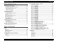
EPSON Stylus Pro 7000 Revision B Contents Chapter 1 Product Description Features ...................................................................................................... 12 Consumable Products & Options ........................................................ 13 Standard Accessories ......................................................................... 13 Print Specifications ............................................................................... 14 Printing Specifications........
EPSON Stylus Pro 7000 Chapter 2 Operating Principles Component List & Illustrations ................................................................ 55 Print Mechanism Components ............................................................ 55 EPSON Stylus Pro 7000 Body & Stand ............................................. 57 Carriage Components......................................................................... 57 Paper Feed Path & Components........................................................
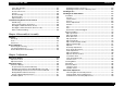
EPSON Stylus Pro 7000 Paper Not Straight ............................................................................ 101 Reload Paper ..................................................................................... 101 Please Lower Lever........................................................................... 102 Ink Out................................................................................................ 102 No Ink Cartridge ................................................................
EPSON Stylus Pro 7000 Revision B Cover Open Sensor Assembly......................................................... 200 USB ID Copy/Backup .............................................................................. 201 Extracting the USB-ID Copy Program ............................................. 201 After Extracting the Program ........................................................... 201 Running the Program .........................................................................
CHAPTER 1 PRODUCT DESCRIPTION
EPSON Stylus Pro 7000 Revision B Paper Save feature searches for the front edge of the roll paper before 1.1 Features printing to make sure no paper at the leading edge is wasted The EPSON Stylus Pro 7000 is an 24-inch wide, 6-color ink jet printer with professional color output. It has the same printheads as the EPSON Stylus Pro 9000. The EPSON Stylus Pro 7000 provides the following major features and more.
EPSON Stylus Pro 7000 Revision B 1.1.1 Consumable Products & Options Table 1-2. Consumables & Options (continued) Name Table 1-2.
EPSON Stylus Pro 7000 Revision B 1.1.
EPSON Stylus Pro 7000 Revision B 1.1.3 Paper Specifications paper from the core *3: At the point where the rear edge comes free from the core (approx. last 30 cm.), print quality is no longer guaranteed. *4: If a 3” core is used, the EPSON-exclusive optional 3” roll paper spindle is required ROLL PAPER SPECIFICATIONS C A U T IO N Paper must have no wrinkles, tears, or folds plus the surface should be smooth.
EPSON Stylus Pro 7000 Revision B Plain paper CUT SHEET SPECIFICATIONS C A U T IO N For paper meeting the following requirements, only the feeding operation is guaranteed. Paper must have no wrinkles, tears, or folds plus the surface should be smooth •Size = see Table 1-5 above (plus the following requirements) •Thickness = 0.08~0.11mm (0.003~0.0044”) •Weight = 64~90gf/m2 (17~24 lb.
EPSON Stylus Pro 7000 Revision B 1.1.4 Printable Area Table 1-7. Printable Area PW LM RM TM Heading Roll Paper Cut Sheets PW (width) 210 ~ 610mm (8.27 ~ 24”) 210 ~ 610mm (8.27 ~ 24”) PL (length) Max. 90m (298.8’) 297~915mm (11.8~36.4”) LM (left margin) 3mm/15mm* (0.12~0.59”) 3mm TM (top) 3mm/15mm* 3mm RM (right) 3mm/15mm* 3mm BM (bottom) 3mm/15mm* 14mm Note: *The size of the margin is determined by the control panel setting.
EPSON Stylus Pro 7000 Revision B 1.1.5 Ink Cartridges 1.1.6 Electrical Specifications Shape: Each ink cartridge is uniquely shaped so the cartridges do not fit in the wrong slots. Ink colors: Black, Cyan, Magenta, Yellow, Light Cyan, Light Magenta Ink life: Two years from production date Ink volume: 110ml Weight: 200g Effective ink: 83.0g Print capacity: Table 1-10.
EPSON Stylus Pro 7000 1.1.7 Reliability Revision B 1.1.8 Environmental Conditions Total print volume: 20,000 pages at A1 size Printheads: 2,000,000,000 dots/nozzle Cutter: Approximately 2,000 sheets (A1) Maintenance parts: Approximately 12,000 sheets Ink pad, Pump unit, Flushing box, Cap assembly, and Head Cleaner are all included in the SP-7000 Maintenance Kit (P/N 1054038) TEMPERATURE/HUMIDITY See the following table. Table 1-11.
EPSON Stylus Pro 7000 Revision B 1.1.9 Controller VIBRATION & SHOCK See the following table. Table 1-12. Vibration and Shock Condition Vibration Resistance Shock Resistance Operating 0.15G 10~55Hz 1G maximum 1ms Storage 0.5G 10~55Hz 2G maximum 2ms CPU: Hitachi SH7043, 33Mhz RAM: 8MB + 2MB (fixed) Interfaces: IEEE1284 USB Type B (one expansion port) Notes X/Y/Z directions Notes: * Make sure the printhead is capped during transportation and storage.
EPSON Stylus Pro 7000 Revision B 1.1.10 Conformity/Safety Approvals 1.1.11 Acoustic Noise 120V Model Approx. 50dB(A) (According to ISO 7779) Safety Standards: UL1950 CSA 22.2 No. 950 EMI: FCC part 15 subpart B class B CSA C108.8 class B 220~240V Model Safety Standards: EN 60950 EMI: EN55022 (CISPR Pub.
EPSON Stylus Pro 7000 Revision B 1.2 Interfaces 1.1.12 CE Marking 220~240V Model Low Voltage Directive 73/23/EEC: EN60950 EMC Directive 89/336/EEC EN55022 Class B EN61000-3-2 EN61000-3-3 EN50082-1 IEC801-2 IEC801-3 IEC801-4 Product Description The EPSON Stylus Pro 7000 is equipped with parallel and USB interfaces as well as an expansion slot for an optional Type-B interface. This section provides information on each of these interfaces.
EPSON Stylus Pro 7000 Revision B 1.2.1 Parallel Interface - Compatibility Mode The ERROR signal is low when there is a: Printer hardware error (fatal error) Table 1-13.
EPSON Stylus Pro 7000 Revision B Table 1-14. Data transmission times Parameter Minimum Maximum tsetup 500 ns - thold 500 ns - tstb 500 ns - tready 0 - tbusy - 500 ns tt-out* - 120 ns tt-in** - 200 ns treply 0 - tack Typical 2 us tnbusy 0 - tnext 0 - * Rise and fall time of every output signal ** Rise and fall time of every input signal Table 1-15. Typical tack time Parallel I/F mode Time required High speed (default) 0.
EPSON Stylus Pro 7000 Revision B Table 1-16. Connector Pin Assignments and signals - Forward Channel Pin No. Pin No. Signal Name Return Pin In/ Out Functional Description 1 -STROBE 19 I Data reception pulse. Data is read at the falling edge of this pules. 2-9 DATA0~7 20-27 I The DATA0 through DATA7 signals represent data bits 0 to7, respectively. Each signal is at high level when data is logical 1 and low level when data is logical 0.
EPSON Stylus Pro 7000 Revision B 1.2.2 Parallel Interface - Nibble Mode Table 1-18. Connector Pin Assignments - Reverse Channel Pin No. Table 1-17. Transmission Specifications Description 1 Signal Name HostClk Return In/ Pin Out I Host clock signal. 20-27 I The DATA0 through DATA7 signals represent data bits 0 to7, respectively. Each signal is at high level when data is logical 1 and low level when data is logical 0.
EPSON Stylus Pro 7000 Revision B 1.2.3 Parallel interface - ECP mode Table 1-19. Transmission Specifications Description Transmission mode IEEE-1284 ECP mode Synchronization Refer to IEEE-1284 specification Handshaking Refer to IEEE-1284 specification Signal level IEEE-1284 level 1 device Adaptable connector See forward channel Data trans.
EPSON Stylus Pro 7000 Revision B Table 1-20. Connector Pin Assignments - ECP Mode Table 1-20. Connector Pin Assignments - ECP Mode Pin No. 1 2-9 10 11 Signal Name Return In/ Pin Out HostClk Data0-7 19 20-27 PeriphClk PeriphAck 28 29 Functional Description nReverseReq uest 30 I This signal goes low to change to the reverse channel. 32 nPeriphRequ est 29 O This signal produces a host interrupt.
EPSON Stylus Pro 7000 Revision B 1.2.4 USB Device ID Standard :“Universal Serial Bus Specifications Revision 1.0” “Universal Serial Bus Device Class Definition for Printing Devices Version 1.0” Bit rate :12Mbps (Full speed device) Data encoding :NRZI Adaptable connector :USB series B <00H><4EH> MFG: EPSON CMD: ESCPL2, BDC MDL: Stylus[SP]Pro[SP]7000 CLS: PRINTER DES: EPSON[SP]Stylus[SP]Pro{SP]7000 NOTE: To use USB interface: set “PARA.I/F=COMPAT.” in the Printer Settings Menu.
EPSON Stylus Pro 7000 Revision B 1.2.5 TYPE-B Optional Interface 1.2.6 Preventing Data Transfer Time-Outs The EPSON Stylus Pro 7000 supports a Type-B interface (level 2). Generally, hosts abandon data transfer to peripherals when a peripheral is in the busy state for dozens of seconds continuously. To prevent hosts from entering this kind of time-out period, the printer slows down the data reception rate to about one byte per second when there is less than 4kb of free space in the printer buffer.
EPSON Stylus Pro 7000 Revision B Interface status and selection 1.2.7 Interface Selection The SP 7000 has one slot for an optional Type-B interface and two built-in interfaces; the USB and parallel interfaces. The printer has only two internal BUS lines for the interfaces, so the parallel and USB interfaces share one line while the other line is exclusive to the Type-B interface.
EPSON Stylus Pro 7000 Revision B 1.3 PHYSICAL SPECIFICATIONS SETUP GUIDELINES PRINTER DIMENSIONS & WEIGHT When setting up the printer on a desk or table top, refer to the instruction and illustration below. (When setting up the printer using the optional stand, see the setup guide that comes with the stand for details.) Dimensions: 1100 x 572 x 560mm (WxDxH) (43.8 x 22.8 x 22.3 inches) Weight: 43.5Kg (95.7 lb.s) 1. Make sure the printer is 60~80cm (24~32”) off the floor. 2.
EPSON Stylus Pro 7000 Revision B CUTTER SPECIFICATIONS Attributes: Consumable item that is replaced by the user, and it is made of very hard steel, so the blade can be chipped. Handle carefully to avoid cuts to yourself and to avoid chipping the blade. Life: The cutter can cut well over 2,000 sheets of paper, but the actual wear-and-tear depends on the type and thickness of the paper used.
EPSON Stylus Pro 7000 Revision B 1.4 Control Panel Table 1-22. Buttons and Functions This section describes the control panel, the buttons, the lights, and the way you make settings.
EPSON Stylus Pro 7000 Revision B LED INDICATORS Table 1-23.
EPSON Stylus Pro 7000 Revision B 1.4.1 Indicator Status in Normal Mode Table 1-26. Pause Indicator Table 1-24. Operate Indicator Printer Status Indicator With power on and in any status other than those listed below. On While processing data and during power off sequence Flashing Fatal error Flashing Reset, timer IC reset/NVRAM clear On Table 1-25.
EPSON Stylus Pro 7000 Revision B 1.4.2 Control Panel Messages Table 1-29. Control Panel Messages (continued) Display Message Table 1-28. Paper Source Indicator Printer Status Indicator Selected paper source On Fatal error Flashing Roll paper and sheet sizes are different Flashing Reset, timer IC reset/NVRAM clear On READY * WAIT * Printer status and error messages appear on the control panel display. The table below lists the messages. INK CHARGING nnn% Table 1-29.
EPSON Stylus Pro 7000 Revision B 1.4.3 Panel Display Priority Table 1-29. Control Panel Messages (continued) Display Message UNABLE TO PRINT RELOAD PAPER REMOVE PAPER PAUSE INK LOW MAINTENANCE REQ.
EPSON Stylus Pro 7000 Revision B To use cut sheets 1.5 Loading Paper smaller than A3+ size cut sheets To automatically cut off the printed roll paper after printing: 1. Select Sheet using the Paper Source button. 2. Make sure the paper set lever is in the forward (set) position, and load a sheet in the paper insertion slot 3. Load the paper from the paper insertion slot and align it with the paper guideline.
EPSON Stylus Pro 7000 Revision B Exiting SelecType mode 1.6 SelecType Settings Select one of the following methods to exit SelecType mode: Entering SelecType mode Press the Pause button while in SelecType mode; the printer is ready To access the control panel settings, press the SelecType button while the printer is not printing. The printer enters the SelecType mode and cannot print. Using SelecType mode 1. TEST PRINT MENU PRINTER STATUS MENU PAPER CONFIG. MENU Replace the cutter.
EPSON Stylus Pro 7000 Revision B Platen gap 1.6.1 Printer Setting Menu You can adjust the platen gap using this option. (See “Platen Gap Mechanism” on page 70 for details.) Table 1-31. Printer Setting Menu Display Message Options Notes PLATEN GAP Auto Wide Adjusts the platen gap. (Normally, leave set to Auto.) PAGE LINE ON OFF When Auto Cut Off is selected on the control panel, this setting determines whether a line for manual cutting is printed.
EPSON Stylus Pro 7000 Revision B 1.6.2 Test Print Menu 1.6.2.2 Status sheet Table 1-32. Test Print Menu Display Message Item Notes NOZZLE CHECK Print Check the printout, any missing lines mean the nozzle(s) are clogged. STATUS SHEET Print Prints the current printer settings. 1.6.2.1 Nozzle check Version: BO289C Ink Pad: 94% Note: the actual pattern prints in color: black, cyan, magenta, light cyan, light magenta, and yellow The firmware version is described as the date the firmware was set.
EPSON Stylus Pro 7000 Revision B Ink Pad = waste ink count, see below Code page = PC 437 (US/Europe) or PC 850 Version = Firmware version E***** F 100~81% remaining Ink Left = see below E**** F 80~61% remaining E***** F 100~81% remaining E*** F 60~41% remaining E**** F 80~61% remaining E** F 40~21% remaining E*** F 60~41% remaining E* F 20~1% remaining E** F 40~20% remaining E F Less than 1% remaining (Maintenance Req 0100) E* F 20%~near end when the ink pads are cal
EPSON Stylus Pro 7000 Revision B 1.6.3 Printer Status Menu 1.6.4 Paper Configuration Settings All consumable items and maintenance parts either run out of their contents or wear out. To determine how much contents (ink) or useful life remains, compare the message and value shown on the control panel display to the corresponding value below and the messages in the table below. E***** E**** E*** E** E* E F F F F F F Table 1-35. Paper Config.
EPSON Stylus Pro 7000 5. Revision B Press Item and confirm that “THICK. PAT. = Print” appears on the display. Then press Enter to print the paper thickness pattern. 1.6.5 Cutter Replacement Menu Print the Status Sheet from the Test Print menu in SelecType mode and see page 43 for information on determining when the cutter needs to be replaced. The following table includes the steps/messages that must be followed to replace the cutter. Table 1-36.
EPSON Stylus Pro 7000 Revision B 1.6.6 Head Alignment Menu The head alignment function allows you to perform the parallelism adjustment. See the illustrations and table below for details. To perform the parallelism adjustment: 1. Load A1-size roll paper. 2. Press the SelecType button and select the Head Alignment Menu. Then press the Item button. 3. If using EPSON special media (paper thickness = 0.2~1.2mm), select “STD”. If using other media, enter the paper thickness in 0.1mm increments.
EPSON Stylus Pro 7000 Revision B 1.7 Maintenance Request Table 1-37. Head Alignment Menu Display Messages Item Notes Select the thickness, to 0.1mm, of the paper you are using to check the platen gap. Normally, leave set to Standard. There are several consumable parts in the printer, and the printer employs separate counters to keep track of each one. The “Maintenance Req. 0100” message appears on the display to warn the user when the Waste Ink pads are about 99% full. PAPER THICK STD 0.0~1.
EPSON Stylus Pro 7000 Revision B 1.8 Service Requests Table 1-38. Service Errors (continued) Service Code When “Service Req nnnnnnnn” appears on the LCD display, a fatal error requiring a service technician has occurred. The nnnnnnnn indicates what needs to be fixed to return the printer to a working state. Table 1-38.
EPSON Stylus Pro 7000 Revision B 1.8.1 Maintenance And Diagnostic Modes MAINTENANCE MODE When the printer is not functioning properly, there are three modes that help you detect what is wrong and can help you fix the problem. These modes are “Maintenance Mode”, “Maintenance Mode 2”, and “Self-Diagnostic Mode”. To enter a mode, press and hold down the appropriate button (described below) while turning on the printer. To enter: For details on how to make settings, see “SelecType Settings” on page 40.
EPSON Stylus Pro 7000 Revision B Table 1-40. Maintenance Mode 2 - (NVRAM) counter value menu MAINTENANCE MODE 2 To enter: While Pressing the Paper Source + Cut/Eject + Paper Feed ↓ buttons, turn the printer on. Table 1-40. Maintenance Mode 2 - (NVRAM) counter value menu LCD Message INIT.
EPSON Stylus Pro 7000 SELF-DIAGNOSTIC MODE Power-on button: Revision B 1.9 Firmware Update Paper Feed ↓ + Cut/Eject + Cleaning This mode is used primarily for replacing worn-out printer parts and adjustment operations. For details, see Chapter 5, "Adjustment". C H E C K P O IN T The information contained in this section is not to be shared publicly.
EPSON Stylus Pro 7000 Revision B 1.10 Jumper Settings 1.11 Initialization The factory default settings for jumper and DIP switch on the Main Board (C299MAIN) are as follows. There are three ways to initialize the EPSON Stylus Pro 7000: Table 1-41.
EPSON Stylus Pro 7000 Revision B 1.12 Transportation Mode To prepare the printer for transportation (drain ink), the user must enter the transportation mode as follows. 1. With the printer turned on, remove all ink cartridges. 2. Turn off the printer. The printer automatically drains the ink and shows the progress as a percent on the LCD panel. The Paper Set lever must be in the set position; otherwise the ink drain sequence won’t execute.
CHAPTER 2 OPERATING PRINCIPLES
EPSON Stylus Pro 7000 Revision B 2.1 Component List & Illustrations Table 2-1. Printer Mechanism Components (continued) Part This section explains the print mechanism and operating principles for the EPSON Stylus Pro 7000. Drive voltage Description Paper feed components 2.1.1 Print Mechanism Components PF motor +42VDC DC Servo motor The printer mechanism of EPSON Stylus Pro 7000 consists of the following mechanism parts.
EPSON Stylus Pro 7000 Revision B Table 2-1.
EPSON Stylus Pro 7000 Revision B EPSON STYLUS PRO 7000 BODY & STAND CARRIAGE COMPONENTS The carriage component functions are described in detail on page 60. AC inlet P-Edge sensor (underneath carriage) Home position sensor Control Panel Linear encoder sensor Platen gap HP sensor Figure 2-2. Carriage Components/Main Parts Figure 2-1.
EPSON Stylus Pro 7000 Revision B PAPER FEED PATH & COMPONENTS Secondary Roller Assembly PF Motor & belt Roll paper R = Paper Width flag L = Paper Set Lever flag P-Rear sensor Frontal view of sensor flags Sideways view of sensor flags P-Front sensor Paper Set Lever Second assembly from right Paper suction fans Figure 2-3. Paper Feed Components - 1 Figure 2-4.
EPSON Stylus Pro 7000 Revision B INK SYSTEM COMPONENTS Ink cartridge holder ELECTRICAL CIRCUIT BOARDS Flushing box Pump motor Ink cartridge Main board Waste ink pads Power supply board Maintenance assembly Figure 2-5. Ink System - Main Parts Figure 2-6.
EPSON Stylus Pro 7000 Revision B 2.2 Description of Components Carriage 2.2.1 Carriage Movement To print on paper as wide as A1+ (24 inches), the carriage must be quite stable and must travel further than the usual carriage. To increase stability, the SP 7000 uses a carriage guide rail instead of the carriage guide shaft. The carriage comes into direct contact with the printer frame using a set of bearings which are attached to the carriage.
EPSON Stylus Pro 7000 Revision B CARRIAGE & CARRIAGE COMPONENTS Do not remove or loosen the screws that secure the CR guide rail, also do not remove the carriage. These parts are adjusted to 1/100th of a mm at the factory. C A U T IO N The SP 7000 uses a special system to ensure the distance between the printhead nozzles and paper remains the same for all supported paper types. The carriage is composed of two sections; main carriage and subcarriage.
EPSON Stylus Pro 7000 Revision B Platen Gap home position flag The PG HP flag is located on the PG gear on the right side of the carriage. This gear connects with the PG gear assembly when the carriage is in the home position and the Pump motor is active. The PG origin sensor is a reflective sensor which detects when this flag is in the PG origin position. Screw Carriage home position flag The CR HP flag is located on the right side of the carriage.
EPSON Stylus Pro 7000 Revision B 2.2.2 Paper Feed Assembly Secondary Roller Assembly CR Guide Rail PF RAIL The main paper feed components are the CR Guide Rail, the Grid Roller Assembly which is attached to the PF Rail, and the Secondary Roller Assembly which attaches to the back of the CR Guide Rail and faces the Grid Roller Assembly. The Grid Roller Assembly is made up of three equal lengths of rollers and their coupling.
EPSON Stylus Pro 7000 Revision B PAPER-FEEDING-RELATED SENSORS Note that the P-Thick and Paper Set Lever sensors as well as their corresponding flags are located next to each other. The sensors employ the two metal flags on top of the Secondary Roller unit (second from the HP side when facing the printer). The left flag is used to determine the paper thickness and the right flag is used to determine the Paper Release Lever position. The following sensors aid in the paper feeding process.
EPSON Stylus Pro 7000 Revision B Pump assembly (head cleaner) 2.2.3 Maintenance Assembly The maintenance assembly for the SP 7000 is similar to the maintenance assembly in the EPSON Stylus Pro 9000. If you are not familiar with the SP 9000, see the following for a detailed description. See Figure 2-5 on page 59 for an illustration of the cleaning.
EPSON Stylus Pro 7000 Revision B 2.2.4 CR Lock Mechanism The printer uses a spring to activate the carriage lock and an electromagnetic solenoid to release it. The spring forces the carriage lock up into the opening at the bottom of the subcarriage when the carriage is in the home position. However, when the CR Motor is running, the solenoid prevents the lock from engaging the carriage.
EPSON Stylus Pro 7000 Revision B 2.2.5 Ink Supply Mechanism INK-RELATED SENSORS There is only one ink cartridge holder for all six cartridges. The design of the holder makes it quite easy to install and replace ink cartridges from the front of the printer. To prevent users from accidently installing a color ink cartridge in the wrong slot, the cartridges have slightly different designs.
EPSON Stylus Pro 7000 Revision B Cover open sensor To ensure proper paper feeding and to prevent paper jams, the front cover must be closed during printing. There is one cover-open sensor that detects when the cover is open using an interlock switch, and this sensor is located near the left side of the main printer opening. When the cover is open, the relay that controls the current to the CR motor and PF motor cuts off the flow of that current.
EPSON Stylus Pro 7000 Revision B 2.3 Printer Mechanism Operation Outline This section describes the various parts of the printer mechanism and how those parts work. the carriage travels. If the position of the carriage according to the Software Servo is different from the position according to the encoder, a fatal error occurs (Service Call 00010005). See page 60 for details on carriage sensors and other parts. 2.3.1 Carriage Mechanism The carriage speed is determined by a software servo system.
EPSON Stylus Pro 7000 Revision B PLATEN GAP MECHANISM CR guide rail To produce high quality printouts, the printer must maintain a constant distance between the printhead nozzles and the paper. To do this the printer measures the thickness of the paper and adjusts the height of the carriage accordingly. View of right side of carriage Carriage The carriage is composed of two parts; the main carriage which is secured to the CR guide rail via bearings, and the subcarriage which holds the printheads.
EPSON Stylus Pro 7000 Revision B When the carriage is in the home position, the PG motor can drive the cam via a series of gears. The motor turns counter clockwise to turn the cam and raise or lower the subcarriage to a set height. The actual platen gap position used during printing depends on the paper thickness as well as the control panel Platen Gap setting. NOTE: You can manually set the platen gap. See Platen Gap in “Printer Setting Menu” on page 41 for information on making this setting. Table 2-4.
EPSON Stylus Pro 7000 Revision B PAPER FEED MECHANISM The EPSON Stylus Pro 7000 feeds roll paper and cut-sheet paper using friction, and the two sensors along the paper feed path provide all necessary information for controlling the paper feed process. The sensors are the P-Rear sensor located on the right near the top of the paper feed path and the P-Front sensor located on the right under the carriage path. See Figure 2-12, "Paper Feed Sensors" on page 64.
EPSON Stylus Pro 7000 Revision B Paper size detection - right and left edges Error type: Reload Paper Return The edge on HP side is found No Yes Paper exists? CR determines distance from opposite side to HP- No Opposite edge is determined Yes Paper exists? CR determines distance from HP to opposite edge (signal CR detects paper edge (HP) side Determine “Nopaper” signal level No Paper loaded CR moves to expected no-paper location Yes Paper exists? CR moves to near vertical guideline Per
Operating Principles Printer Mechanism Operation Outline Return CR moves to 30mm inside right edge Right-top edge detected? No Printer detects leading edge Yes P-Width sensor = Max. reverse feed and feed paper until P-Front = off CR moves to preset position Reverse feed +40mm Max. reverse feed, P-Front sensor P-Front sensor = on? Yes CR moves to 30mm inside left edge Max.
EPSON Stylus Pro 7000 Revision B After paper is loaded in the printer, the printer performs the above left, right, and leading edge detection operations to make sure the paper is inside the printable range of the printheads. If any of these edges is outside of this area, a “Reload Paper” errors. Basic loading procedure Make sure the left edge (near the HP) is lined up with the vertical line of holes in the Lower Paper Guide.
EPSON Stylus Pro 7000 Revision B 2.4 Summary of Control Circuit Operations CN7 Control Panel IC8 CPU/C90A14CA This section summarizes the functions of the (C299MAIN) Main Board and the controls used to operate the printer. 5VDC 28VDC 42VDC IC80 RESET IC Reset signal -2VDC IC15 REGULA TOR IC69 BUS DRV/ LV161284 3.3V DC CN1 Parallel I/F IC13 ASIC/E05B61AA CN2 Type-B Slot Stop signal CN3 USB I/F IC62 USB CTRL/ USS725 IC39 SRAM/8KB IC61 EEPROM D/A adj.
EPSON Stylus Pro 7000 Revision B Table 2-6. Control Circuit Operation (continued) Table 2-6.
EPSON Stylus Pro 7000 Revision B 2.4.1 Power Supply Board Summary Table 2-7. PS Board Signal Summary Depending on the printer model, either 100V AC or 220V AC is supplied to the printer when the printer is plugged into an live outlet. When plugged into a live power outlet, the power supply board is working. C A U T IO N Even after pressing the power switch to turn off the printer, power is supplied to and from the power supply board.
CHAPTER 3 TROUBLESHOOTING
EPSON Stylus Pro 7000 Revision B 3.1 Outline 3.1.2 Remember See this chapter for detailed troubleshooting instructions if the printer is not working properly. Before beginning disassembly turn the printer off, wait for a few seconds after the LCD panel goes blank, and then remove the power cord from the outlet. Also remove any interface cables. 3.1.1 First... C A U T IO N Before starting, confirm or attempt the following: There are no foreign materials inside the printer.
EPSON Stylus Pro 7000 Revision B 3.1.4 Maintenance Errors There are several consumable parts in the printer, and the printer employs separate counters to keep track of each one. The “Maintenance Req. 0100” message appears on the display to warn the user when the Waste Ink pads are about 99% full. The printer can continue to print even though the “Maintenance Req. 0100* message appears instead of the “Ready” or “Printing” message.
EPSON Stylus Pro 7000 Revision B 3.1.5 Service Errors Table 3-1. Service Errors (continued) Service Code When “Service Req nnnnnnnn” appears on the LCD display, a fatal error requiring a service technician has occurred. The nnnnnnnn indicates what needs to be fixed to return the printer to a working state. Explanation 100000004 CPU Vector 4 - General illegal instruction 100000006 CPU Vector 6 - Slot illegal instruction Table 3-1.
EPSON Stylus Pro 7000 Revision B 3.2 Troubleshooting Using the Error Messages Table 3-2. LCD Panel Error Messages LCD message The EPSON Stylus Pro 7000 performs self-diagnostic tests using the data supplied by its various sensors, and if an error is detected by one or more sensors, a corresponding error message appears on the control panel display.
EPSON Stylus Pro 7000 Revision B Table 3-3. Messages That Indicate Service is Necessary Error Code Description Refer to Maintenance Call nnnn 0100 Waste Ink pads is almost full (less than 1% remaining) page 93 00000100 Waste Ink pads must be replaced 00000101 Service Call nnnnnnnn Table 3-3.
EPSON Stylus Pro 7000 Revision B Table 3-4.
EPSON Stylus Pro 7000 Revision B Table 3-6. Maintenance Call nnnn Item Description ERRORS Error messages appear on the LCD to notify the user that the printer cannot print properly under the current conditions. When an error message appears, printing stops and data transfer from the host PC stops. (The parallel interface signal = /ERROR -> “LOW” and BUSY -> “HIGH” and data cannot be entered.
EPSON Stylus Pro 7000 Revision B Table 3-10. Please Load Paper Table 3-8. Please Load xxx Item Description LCD message Please Load xxx LED indicator status Details Recovery Item Description LCD message Please Load Paper Paper check indicator is on and the currently selected paper path indicator flashes. The paper path information is supplied by the PP remote command. LED indicator status The Paper Check indicator in on. Roll paper and cut sheet size settings differ.
EPSON Stylus Pro 7000 Revision B Table 3-13. Paper Not Cut Table 3-12. Cover Open Item Description Item Description LCD message Cover Open LCD message Paper Not Cut LED indicator status N/A LED indicator status Paper Check indicator flashes. Details The front cover is open.When the cover is open the CR cannot move and no printer operations such as cleaning can be performed. If the cover is left open for a long period of time, the printheads may be affected adversely.
EPSON Stylus Pro 7000 Revision B Table 3-15. Correctly Load Paper Table 3-14. Paper Skew Item Description Item Description LCD message Paper Skew LCD message Correctly Load Paper LED indicator status Paper Check indicator flashes. LED indicator status Paper Check indicator flashes. Details Paper skew error occurred. The lateral (horizontal) position of the leading edge and rear edge are off by over 3mm.
EPSON Stylus Pro 7000 Revision B Table 3-18. Replace Ink Cartridge Table 3-16. Return Paper Lever Item Description Item Description LCD message Return Paper Lever LCD message Replace Ink Cartridge LED indicator status N/A LED indicator status The Ink End indicator for the incorrect slot (if an ink cartridge is installed in the wrong slot) or empty ink cartridge is on. Details The Paper Set Lever was moved to the release position during operation.
EPSON Stylus Pro 7000 Revision B Table 3-21. Remove Paper Table 3-19. No Cartridge Item Description Item Description LCD message No Cartridge LCD message Remove Paper LED indicator status The Ink End indicator is on for the ink cartridge that is missing or improperly installed. LED indicator status Paper Check LED is on. Details No ink cartridge installed or the ink cartridge is not fully installed. Details Paper is too thick to allow for head cleaning.
EPSON Stylus Pro 7000 Revision B Table 3-24. Fatal Error Code List (continued) FATAL ERRORS Fatal error messages appear on the LCD panel to warn users that an unrecoverable error has occurred. However, in some cases the printer may recover if turned off and back on. Table 3-23. Fatal Error Item Description LCD message Service Call nnnnnnnn LED indicator status All LED indicators flash. Details A fatal error occurs for one of the following reasons.
EPSON Stylus Pro 7000 Revision B 3.3 Errors That Require a Service Technician SERVICE CALL 00000101 Problem MAINTENANCE CALL 0100 Problem The waste ink pads are almost full, causing a warning error. The printer can continue printing, but this messages overrides status messages such as Ready or Printing.
EPSON Stylus Pro 7000 Revision B SERVICE CALL 00010001 SERVICE CALL 00010002 Problem Problem PF motor out of step - the length of the PF motor internal encoder’s pulse is too long or too short compared to the regular pulse. Solution Make sure there is nothing blocking the grid rollers. If that does not solve the problem, check the PF motor encoder connection. If there still is a problem, try the following.
EPSON Stylus Pro 7000 Revision B Replace the encoder sensor SERVICE CALL 00010004 Replace the CR motor Problem CR motor encoder check error The CR motor makes small revolutions clockwise and counterclockwise. When it turns, the printer checks the encoder output signals to make sure the motor is turning at the correct speed/ distance. If the encoder doesn’t send the correct signal or output data, an error occurs.
EPSON Stylus Pro 7000 Revision B Solution SERVICE CALL 00010006 Replace the Main Board Problem CR motor overcurrent - Feedback from the CR motor (IC33) driver’s 10-pin output (Sense signal) indicates that the CR motor’s current is irregular.
EPSON Stylus Pro 7000 Revision B Replace the PG motor SERVICE CALL 00010009 Replace the Main Board Problem System interrupt watchdog time-out error due to sensor-related error Solution Replace the Main Board SERVICE CALL 0001000D SERVICE CALL 0001000E Problem SERVICE CALL 0001000A Problem CR origin sensor malfunction - CR home position sensor malfunction Cover sensor malfunction - one or both cover open sensors (interlock switch) located at either end of the cover shaft is malfunctioning
EPSON Stylus Pro 7000 Revision B SERVICE CALL 00020000 (NVRAM ERROR) SERVICE CALL 00020001 (INTERNAL RAM ERROR) SERVICE CALL 00020002 (SRAM ERROR) SERVICE CALL 00020003 (DRAM ERROR) Problem Unusual condition detected.
EPSON Stylus Pro 7000 Revision B 3.4 General Errors PAPER OUT This section describes error that can be solved by the user. Problem Paper is not loaded. C H E C K P O IN T By using “Check: Test” function in the built-in self-diagnostic mode, you can check control panel, sensors, encoders function. Refer to Chapter 5, Adjustment, for more details. The rear edge of roll paper has been detected. The print job using cut sheets is finished or the rear edge of cut-sheet paper has been detected.
EPSON Stylus Pro 7000 Revision B LOAD XXX PAPER PAPER JAM Problem Problem The selected paper source (according to the remote PP command) and the paper type selected on the control panel do not match. Solution Load the correct paper or change the panel setting to match the type of paper loaded in the printer. A paper jam occurs when during printing, paper feeding, or paper cutting the carriage is not able to move properly (due to paper catching on some part).
EPSON Stylus Pro 7000 Revision B PAPER NOT CUT RELOAD PAPER Problem Problem The paper that was supposed to be cut was not cut completely, or the paper was cut but is still in front of the P-Front sensor. Solution Remove the cut paper if it is on or near the Front Cover and Lower Paper Guide. Replace the cutter if it is worn out. This error occurs when, 1) The front edge is loaded too far and the paper is not in the loading position after it is reverse fed.
EPSON Stylus Pro 7000 Revision B If the error recurs even after reloading the paper, make sure the paper-end sensor on top of the carriage is installed correctly and working properly. INK OUT Problem One or more ink cartridges have run out of ink, a near-end cartridge has been reinstalled, or an unsupported ink cartridge has been installed.
EPSON Stylus Pro 7000 Revision B 3.5 Troubleshooting Based on Your Printout REMOVE PAPER Problem Printer cannot perform cleaning because of thick paper. (The printheads are too far away from the Cap Assembly.) This error occurs under the following conditions. This section describes conceivable print quality problems that may occur with this printer and the troubleshooting points for those errors. Table 3-25.
EPSON Stylus Pro 7000 3. Revision B If the extra ink charge does not clear the clogged nozzles, confirm the following. UNEVEN PRINTING/POOR RESOLUTION There is no damage to or foreign materials in/around the rubber of If printout quality suffers from unevenness, poor quality, or similar problems, check the following. the Cap Assembly The Cap Assembly valve is operating normally (if it is not, the Cap 1.
EPSON Stylus Pro 7000 Revision B SMUDGED OR MARRED PRINTOUT (FRONT) WHITE OR BLACK BANDING The front, or top, side of the paper can become smudged or marred if it rubs against the printhead surface. If this happens, verify the following. If white or black banding (lines across the page) appear on your printout, try the following. 1. 1. Cleaning 2. If multiple cleaning cycles don’t clear the banding problem, try adjusting the heads as described below. 2.
CHAPTER 4 DISASSEMBLY & ASSEMBLY
EPSON Stylus Pro 7000 Revision B 4.1 Summary This section describes the disassembly and assembly methods for the EPSON Stylus Pro 7000. However, full assembly instructions are not given apart from following the disassembly instructions in reverse order, and where special instructions are necessary, reassembly points are provided. Where “Caution” and “Reassembly” notes are given, be sure to confirm these contents BEFORE starting the corresponding procedure.
EPSON Stylus Pro 7000 Revision B 4.1.1 Warnings Before proceeding with any disassembly or assembly work, make absolutely sure of the following. W A R N IN G The power switch is located on the control panel. Any time the printer is plugged into a power outlet, power is flowing through the PS board. Unless otherwise stated, always turn off the printer, wait several seconds, and then unplug the power cable from the outlet before servicing a printer.
EPSON Stylus Pro 7000 W A R N IN G C A U T IO N Revision B Danger of explosion if the battery is incorrectly replaced. Replace only with the same or equivalent type recommended by the manufacture. Dispose the used batteries according to government’s law and regulations. C A U T IO N Risque d’explosion si la pile est remplacée incorrectment. Ne remplacer que par une pile du même type ou d’un type équivalent recommandé par le fabricant.
EPSON Stylus Pro 7000 C H E C K P O IN T Revision B If you find it is necessary to perform service on a part not described in this chapter, be sure to check the afterservice parts situation before beginning the service. If you need to remove the ink tubes or other ink related parts, see “Transportation Mode” on page 53 to drain the ink before removing anything. If necessary (i.e.
EPSON Stylus Pro 7000 Revision B 4.1.3 Screw List Table 4-2. Screws (continued) Type Color Truss screw M4x8 white (+) Truss screw Toothed washer M3 white outer teeth Toothed washer M4 white outer teeth The following table lists all the screws used in this printer. Table 4-2.
EPSON Stylus Pro 7000 Revision B 4.2 Disassembly Flow Refer to the following flowchart when determining the disassembly flow. 4.2.1 Remove Panel & Housing 4.2.2 Remove Circuit Board 4.2.3 Disassemble Printer Mechanism Panel Unit Power Supply Board Replace Waste Ink Pads L/R Side Covers C299MAIN Board Replace Printheads H Top Cover CR Motor / Pulley Assembly Front Cover PF Motor / Pulley Assembly Roll Cover Maintenance Assembly Lower Paper Guide Sensors Rear Panel 4.2.
EPSON Stylus Pro 7000 Revision B 4.2.1 Removing the Housing 4.2.1.1 Panel Unit Removal This sections describes the removal procedure for printer housing parts. See below for an illustration of the housing parts. Roll Cover Assembly 1. Upper Paper Guide (behind H Top Cover) H Top Cover Release the clips on both sides of the control panel unit and pull slightly away from the R Side Cover.
EPSON Stylus Pro 7000 2. Revision B 4.2.1.2 R Side Cover Removal Remove the FFC cable from the connector and hook. Panel Unit Connector Hook 1. Remove the control panel unit as described in 4.2.1.1 “Panel Unit Removal”. 2. Open the roll paper cover. 3. Push back the Paper Set Lever to the released position, remove two black screws (CBP: M4x10) from the lever handle, and remove the handle. 4. Using a (-) driver or similar tool, remove the lever opening cap.
EPSON Stylus Pro 7000 5. Revision B Open the Roll Cover and from the inner side, remove one black screw (CBP:M4x10). 7. Open the front cover and remove one black screw (CPP: M4x12). Roll Cover One screw on inside of right cover One screw Figure 4-9. R Side Cover Removal 3/4 8. Figure 4-7. R Side Cover Removal 1/4 6. Return the Paper Set Lever to the set position, and pull off the R Side Cover to the right.
EPSON Stylus Pro 7000 Revision B 4.2.1.3 L Side Cover Removal 4.2.1.4 I/C Holder Cover Removal 1. Open the roll paper cover. 1. Remove the L Side cover as described in 4.2.1.3 “L Side Cover Removal”. 2. From the inner side, remove one black screw (CBP:M4x10). 2. Open the I/C Holder Cover. 3. Remove two white screws (CBS:M3x10). Roll Cover One screw I/C Holder Cover Frame I/C Holder Cover Figure 4-11. L Side Cover Removal 1/2 3.
EPSON Stylus Pro 7000 Revision B 4.2.1.5 H Top Cover Removal 1. Remove the R Side Cover as described in 4.2.1.2 “R Side Cover Removal”. 2. Remove the L Side Cover as described in 4.2.1.3 “L Side Cover Removal”. 3. Remove the I/C Holder Cover as described in 4.2.1.4 “I/C Holder Cover Removal”. 4. Open the Front Cover 5. From the right side, remove two screws (CUPS:M4x8) and from the left side, remove three screws (CUPS:M4x8). H Top Cover Two screws Figure 4-14.
EPSON Stylus Pro 7000 Revision B 4.2.1.6 Rear Cover Removal 1. 4. Remove three white screws (CBS:M4x8) securing the lower section of the cover, and remove three white screws (CBS:M4x8) securing the upper section of the cover. 5. Remove the Rear Cover by pulling to the rear (lift and pull if necessary). From the rear, remove two white screws (CPS:M3x12) securing the optional interface cover, and remove the optional interface cover.
EPSON Stylus Pro 7000 Revision B 4.2.1.7 Paper Guide L2 Removal 1. From the front, remove four white screws (Truss:M4x6), and remove the Paper Guide L2. When replacing the Paper Guide L2, make sure the five tabs at the top of the guide slide in between the metal and black cushion. Then secure with the screws. Paper Guide L Paper Guide L2 Paper Guide L2 Two screws Five tabs If just one of the tabs is not inserted properly, roll paper will most likely still feed normally, but cut sheets might not.
EPSON Stylus Pro 7000 Revision B 4.2.1.8 Roll Paper Cover Removal 3. 1. Open the Roll Paper Cover. 2. Remove two white screws (CPS:M4x8) securing the black spindle support on the left, and then remove the spindle support. Remove two white screws (CPS:M4x8) securing the gray spindle support on the right, and then remove the spindle support. Roll Paper Cover Roll Paper Cover Two screws Brake pin Brake pin Two screws Spindle support Spindle support Figure 4-21.
EPSON Stylus Pro 7000 Revision B 4.2.1.9 Front Cover Removal 4. 1. Open the Front Cover. 2. Push in the two hooks to the left of the cover and remove the front shaft cover. Front cover Spring catch E-ring spring L Remove the two resin stopper clips (white plastic) from the front cover support shaft on the left, and then pull out the front cover support shaft to the left. Be aware that the front cover spring L and Front Cover come free at this time.
EPSON Stylus Pro 7000 Revision B 4.2.2 Circuit Board Removal This section explains how to remove the Circuit Board (C299PSU) and the Main Board (C299MAIN). 4.2.2.1 Power Board Removal W A R N IN G Unplug the AC power cable and wait at least five minutes before removing the power supply board to make sure there is no residual power left in the board’s condensers. 1. Remove the Rear Cover as described in “Rear Cover Removal” on page 118. 2.
EPSON Stylus Pro 7000 Revision B 4.2.2.2 C299MAIN Board Removal Table 4-4. C299MAIN Board Connectors 1. Remove the Rear Cover as described in “Rear Cover Removal” on page 118. 2. Remove the cables from the following connectors. Table 4-4.
EPSON Stylus Pro 7000 3. Revision B Remove the two screws (CP(W) M3x8) securing the Type-B Option Slot Cover, and remove the cover. Then remove seven screws (CP(W) M3x6) securing the Main board and remove the board. Three screws 4.2.2.3 AC Inlet Removal 1. Remove the Rear Cover as described in “Rear Cover Removal” on page 118. 2. Remove the connector from CN001 on the PS board. 3. Remove one white screw (CUPS:M4x8) securing the AC inlet, the AC inlet ground cable, and the toothed washer (M4). 4.2.
EPSON Stylus Pro 7000 Revision B 4.2.3 Printer Mechanism Disassembly This section describes the Printer Mechanism components and the procedure for disassembly. C A U T IO N Do not remove or loosen the screws that secure the CR guide rail, also do not remove the carriage. These parts are adjusted to 1/100th of a mm at the factory. Do not attempt any kind of service or adjustment to the frame or parts attached directly to the frame.
EPSON Stylus Pro 7000 Revision B 4.2.3.1 Replacing the Waste Ink Pads 2. To keep the printhead clean and maintain quality, the printer drains waste ink away from the printhead surface and nozzles into the Waste Ink Pads.
EPSON Stylus Pro 7000 4. Revision B The waste ink box clamp is held on by hooks. While pulling out the hooks to release them, remove the clamp from the box.
EPSON Stylus Pro 7000 Revision B 4.2.3.2 Removing the Suction Fans 1. Remove Paper Guide L2 as described in “Paper Guide L2 Removal” on page 119. 2. Remove the Waste Ink Box from the printer as described in steps 1 to 3 only of “Replacing the Waste Ink Pads” on page 126. 3. Remove the two screws (CP(W):M4x8) and one screw (CP(W):M4x40) securing the fan duct, and then remove the fan duct. Suctions fans One screw Fan duct Two screws One screw Connector Figure 4-32. Suction Fan Removal 4.
EPSON Stylus Pro 7000 Revision B 4.2.3.3 Replacing the Printheads C A U T IO N A D J U S T M E N T R E Q U IR E D 3. The printer uses two printheads, B Head and C Head, and although they are similar you need to make sure you do not mix the heads. One is for dark inks and the other is for light inks. Therefore make sure you prepare and install the correct replacement head.
EPSON Stylus Pro 7000 5. Revision B Remove one screw (CP(W) M3x6) securing the damper holder, unhook the ink tubes from the damper holder, and then remove the damper holder. Ink tubes Ink tubes Damper holder 6. Pull out the dampers. To pull out the dampers, place the tip of a flat-head screwdriver or similar tool under the protrusion on the left side of a damper and steady the damper with the forefinger of your other hand. Gently but firmly pull the damper straight out.
EPSON Stylus Pro 7000 7. Revision B Using round-nosed pliers, remove the “Tension Spring, 9.9” from the C head on the right. 10. Repeat steps 7 through 9 for the B head. C H E C K P O IN T Printhead voltage ID Tension Spring, 9.9 When replacing the printheads, fold the flat cable behind the printhead and make sure the printhead snaps fully into place. When properly installed, the printhead ID will be directly behind and at the same height as the PG Cam Shaft.
EPSON Stylus Pro 7000 Revision B 4.2.3.4 Removing the CR Board Assembly 1. 6. Remove the R Side Cover as described in “R Side Cover Removal” on page 114. 2. Remove the L Side Cover as described in “L Side Cover Removal” on page 116. 3. Remove the I/C Holder Cover as described in “I/C Holder Cover Removal” on page 116. 4. Remove the H Top Cover as described in “H Top Cover Removal” on page 117. While holding down the CR Board (left edge), remove two FFC cables from the FFC lock-type connectors.
EPSON Stylus Pro 7000 Revision B 4.2.3.5 Removing the Cutter Housing C H E C K P O IN T Remember to use a plastic tie band to secure the encoder sensor, P_EDGE sensor, and ground cables in front of the cutter housing. Otherwise, the cables may rub against and interfere with the linear encoder. Before each step in this operation, take a good look at the relative parts and where they are or how they are housed.
EPSON Stylus Pro 7000 C A U T IO N Revision B Do not tighten the four screws securing the cutter housing too tightly. They can pull out the female screws on the carriage side, which warps the cutter housing. Since the encoder sensor is attached to the cutter housing, the encoder may have problems (trust me!). If you run into the following or similar errors after replacing the cutter housing, loosen the screws a little and try again. Service Req. 0001000F Service Req.
EPSON Stylus Pro 7000 Revision B 4.2.3.6 Removing the Cutter Solenoid 4. 1. Remove the cutter housing as described in “Removing the Cutter Housing” on page 133. 2. Push the cutter down (second tab from top) while moving the cutter cap (first tab from top) to the right to release it from the CR lock guide. Remove the cutter and cutter spring. 3. Remove the cutter cap, cutter solenoid core, and cutter solenoid spring.
EPSON Stylus Pro 7000 Revision B 4.2.3.7 Removing the CR Encoder Sensor 4.2.3.8 Removing the P_Edge Sensor 1. Remove the cutter housing as described in “Removing the Cutter Housing” on page 133. 1. Remove the cutter housing as described in “Removing the Cutter Housing” on page 133. 2. Remove one screw (CPP M3x8) securing the CR Encoder Sensor, ground, and washer (M3). Then remove the CR Encode Sensor. 2. Remove one screw (CBP M3x6) securing the P_Edge sensor and remove the sensor.
EPSON Stylus Pro 7000 Revision B 4.2.3.9 Removing the Ink Cartridge Holder & Slots 7. The Ink Cartridge Holder is made up of six individual slots, one for each color of ink. The following instructions describe how to access and remove one of those slots. C A U T IO N A D J U S T M E N T R E Q U IR E D Pull out the cables through the opening in the L Side frame, and remove the cables from the four clamps.
EPSON Stylus Pro 7000 9. Revision B Remove one screw (CUPS M3x6) securing the Cover-open sensor to the rear of the I/C Holder Frame. Then remove the Cover-open sensor. 12. Remove six screws (CUPS M3x6) and two screws (CUPS M4x6) securing the I/C Holder Frame on the top. I/C Holder Frame Cover-open sensor Two screws One screw One screw (M3x6) One screw (M4x6) Six screws Figure 4-53. Holder Frame Removal - top Figure 4-51. Cover-Open Sensor & Holder Frame Removal - R side 10.
EPSON Stylus Pro 7000 Revision B 14. Unscrew the six ink tube screws (M6) between the ink pipes and ink cartridge holder slots. Also remove the O-rings. Ink pipes Ink tube screws and O-rings Figure 4-54. Disconnecting the Ink Pipes 15. For the slot you want to remove, remove the corresponding two screws (CPS M3x12) securing the slot frame to the base. Remove that slot frame. Two screws Slot frame Figure 4-55.
EPSON Stylus Pro 7000 Revision B 4.2.3.10 Removing the Ink Cartridge Sensor 1. 2. Remove the Ink Cartridge Slot as described in “Removing the Ink Cartridge Holder & Slots” on page 137. Remove the Ink Cartridge Sensor cable from the hooks as shown below, and then remove the cable completely through the bottom. 4. Remove two screws (CUPS M3x6) securing the needle frame and remove the frame. 5. Remove one screw (CBS M2x8) securing the I/C sensor to the needle frame and remove the I/C sensor.
EPSON Stylus Pro 7000 Revision B 4.2.3.11 Removing the CR Motor/Pulley Assembly 1. Remove the R Side Cover as described in “R Side Cover Removal” on page 114. 2. Remove the L Side Cover as described in “L Side Cover Removal” on page 116. 3. Remove the Rear Cover as described in “Rear Cover Removal” on page 118. 4. Remove the CR Motor cable from the C299MAIN board connector (refer to Table 4-4, “C299MAIN Board Connectors,” on page 123 for details) and harness clamps.
EPSON Stylus Pro 7000 Revision B 4.2.3.12 Removing the PF Motor Assembly 1. Remove the R Side Cover as described in “R Side Cover Removal” on page 114. 2. Remove the L Side Cover as described in “L Side Cover Removal” on page 116. 3. Release the PF Motor harnesses from the harness clamp attached to the inner side of the L Side Frame. Then, disconnect their connectors and take them out from the hole in the L Side Frame.
EPSON Stylus Pro 7000 Revision B 4.2.3.13 Removing the Maintenance Assembly A D J U S T M E N T R E Q U IR E D Two Sensor Harnesses If you replace the waste ink absorbers because the service call error 0000100 occurs, you need to replace the specified parts* in the Maintenance Assembly. After replacing them, be sure to initialize the following counters: Clamp Waste ink counter Pump Motor ASSY.
EPSON Stylus Pro 7000 Revision B 6. Perform steps 1 and 2 of the “Replacing the Waste Ink Pads” on page 126. 7. Remove the four (CUPS M4x6) screws securing the Maintenance Base Assembly to the printer main body and remove the Maintenance Base Assembly. Maintenance Base Assembly Screw (M4x6) Screws (M4x6) (+) Screw Driver Figure 4-67. Removing the Maintenance Base Assembly - 3 Figure 4-65. Removing the Maintenance Base Assembly - 1 8.
EPSON Stylus Pro 7000 C A U T IO N Revision B When reassembling the Maintenance Bracket, be sure to lift up the bracket as you secure the screws. Otherwise you may Cause damage to the nozzle surface by scraping the nozzle surface on the capping flag (no error message!) Cause clogged nozzles and/or cause the printer to leak ink if the cap and nozzle surface do not form a good seal in the capping position; make sure both caps are tightly sealed like the one on the left (no error message!).
EPSON Stylus Pro 7000 Revision B 4.2.3.14 Removing the Pump Motor Assembly 1. Remove the Maintenance Assembly as described in “Removing the Maintenance Assembly” on page 143. 2. Release the harness for the Pump Motor Assembly from the cable clamp. 3. Remove the three (CP(W) M3x8) screws securing the Pump Motor Assembly to the Maintenance Base Assembly and remove the Pump Motor Assembly. Pump Motor Assembly Clamp Screws (M3x8) Figure 4-69.
EPSON Stylus Pro 7000 Revision B 4.2.3.15 Removing the Cap Assembly 1. Remove the Maintenance Assembly as described in “Removing the Maintenance Assembly” on page 143. 2. Remove the four (CUPS M4x3) screws securing the R Side Frame Sub Assembly and remove the R Side Frame Sub Assembly. C A U T IO N R Side Frame Sub Assembly Check for the points below when removing/mounting the Cap Assembly. Push the cap part down to the valve part and check that the cap part rebounds with spring force.
EPSON Stylus Pro 7000 Revision B 4.2.3.16 Removing the Pump Assembly 4.2.3.17 Removing the Cleaner Head 1. Remove the Maintenance Assembly as described in “Removing the Maintenance Assembly” on page 143. 1. Remove the Maintenance Assembly as described in “Removing the Maintenance Assembly” on page 143. 2. Remove the Cap Assembly as described in “Removing the Cap Assembly” on page 147. 2. Remove the Cap Assembly as described in “Removing the Cap Assembly” on page 147. 3.
EPSON Stylus Pro 7000 Revision B 4.2.3.18 Removing the Flushing Box Assembly 1. Remove the Maintenance Assembly as described in “Removing the Maintenance Assembly” on page 143. 2. Using tweezers, remove the Cleaner Head from the Pump Assembly. NOTE: Make sure the Cleaner Head surface is free from any dirt, dust, or grease. Also, when mounting it, use tweezers to keep the wiping side of the Cleaner Head clean. 3.
EPSON Stylus Pro 7000 Revision B 4.2.3.19 Removing the HEAD_SLIDE Sensor Assembly 1. 2. 3. 4. Remove the R Side Cover as described in “R Side Cover Removal” on page 114. Push the carriage lock using your finger to unlock the carriage and move the carriage from the home position to the left. 5. Remove the Rear Cover as described in “Rear Cover Removal” on page 118. Remove the one (CP(W) M3x6) screw securing the HEAD_SLIDE Sensor Assembly and remove the HEAD_SLIDE Sensor Assembly. 6.
EPSON Stylus Pro 7000 Revision B 4.2.3.20 Removing the CR_HP Sensor 1. Remove the R Side Cover as described in “R Side Cover Removal” on page 114. 2. Push the carriage lock using your finger to unlock the carriage and move the carriage from the home position to the left. 3. Disconnect the harness from the CR_HP Sensor connector. 4. Release the hook fixing the CR_HP Sensor and remove the CR_HP Sensor. Hooks CR_HP Sensor Connector Figure 4-77.
EPSON Stylus Pro 7000 Revision B 4.2.3.21 Removing the Release Sensor/P_THICK Sensor P_THICK Sensor Right: Release Sensor that detects the paper hold sensor condition (set or released). Left: Detection flag P_THICK Sensor that detects paper thickness (normal or thick) 1. Remove the R Side Cover as described in “R Side Cover Removal” on page 114. 2. Remove the L Side Cover as described in “L Side Cover Removal” on page 116. 3.
EPSON Stylus Pro 7000 Revision B 4.2.3.22 Removing the P_FRONt Sensor Assembly Paper Guide L 1. Remove the R Side Cover as described in “R Side Cover Removal” on page 114. 2. Remove the L Side Cover as described in “L Side Cover Removal” on page 116. 3. Remove the I/C Holder Cover as described in “I/C Holder Cover Removal” on page 116. 4. Remove the H Top Cover as described in “H Top Cover Removal” on page 117. 5. Remove the Rear Cover as described in “Rear Cover Removal” on page 118. 6.
EPSON Stylus Pro 7000 Revision B 4.2.3.23 Removing the P_REAR Sensor Assembly 1. Remove the R Side Cover as described in “R Side Cover Removal” on page 114. 2. Remove the L Side Cover as described in “L Side Cover Removal” on page 116. 3. Remove the I/C Holder Cover as described in “I/C Holder Cover Removal” on page 116. 4. Remove the H Top Cover as described in “H Top Cover Removal” on page 117. 5. Remove the Rear Cover as described in “Rear Cover Removal” on page 118. 6.
EPSON Stylus Pro 7000 Revision B 4.2.3.24 Removing the Cover Sensor Assembly 1. Perform the Steps 1 to 13 in “I/C Holder Cover Removal” on page 116. 2. Separate the harnesses for the Cover Sensor Assembly from the six harness connectors for the Ink Cartridge Sensor and harness bundle for the Cover Sensor Assembly. 3. Remove the two (CP(W) M2x12) screws securing the Cover Sensor Assembly and Cover SW Holder, and remove the Cover Sensor Assembly.
CHAPTER 5 ADJUSTMENT
EPSON Stylus Pro 7000 Revision B 5.1 Adjustment Outline 5.1.1 Adjustment Tools This section describes the adjustment procedures necessary after replacing certain parts and explains how to perform those adjustment procedures. The necessary tools for performing adjustment procedures on this printer are shown below. Table 5-1. Adjustment Tools Before beginning any adjustment procedure, make sure of the following.
EPSON Stylus Pro 7000 Revision B 5.1.2 Adjustment Items Table 5-2. Service Parts & Required Adjustments (continued) All parts that require adjustment when replaced are listed in the table below. Service Operation Table 5-2. Service Parts & Required Adjustments Service Operation Printhead replacement C299 Main Board replacement (board is alive) C299 Main Board replacement (board is dead) Adjustment Items 1. 2. 3. 4. 5. 6. 7. 1. 2. 3. 4. 5. 6. 7. 8. 9. 1. 2. 3. 4. 5. 6.
EPSON Stylus Pro 7000 Revision B 5.2 Adjustment Steps REQUIREMENTS FOR PARAMETER BACKUP This section describes the detailed steps for performing the adjustment procedures listed in Table 5-2. 5.2.1 Parameter Backup (Conforms to PCMCIA Rel 2.1/JEIDA Ver 4.2 (Type II) / 5V Read/Write operation) Part # 1050073 (Fujitsu: MB98A81183-15) Memory card writing utility The Main Board contains NVRAM (EEPROM) which is used to store the parameter information and firmware commands that control the printer.
EPSON Stylus Pro 7000 Revision B BACKING UP PARAMETERS FROM MAIN BOARD TO PC CARD DOWNLOADING PARAMETERS FROM PC CARD TO NEW BOARD 1. 1. Make sure the access cover is removed from the top of the Upper Paper Guide, and make sure the Control Panel is attached. 2. Insert the PC card containing the backup data (top facing the outside of the printer) into the PC card slot connector on the Main Board, and turn on the printer. 3. Make sure the following message appears on the LCD.
EPSON Stylus Pro 7000 Revision B BACKUP/DOWNLOAD ERROR RECOVERY If an error occurs during the backup or download procedure, the following message appears on the LCD. End [Error] If you see the message above, one of the following errors has occurred. Flash memory/ write error Flash memory/ erase error PC card/ write error PC card/ erase error Using a different PC card, try the operation again.
EPSON Stylus Pro 7000 Revision B 5.2.2 Firmware Update UPDATING FIRMWARE VIA THE PC Since the firmware is written into the Flash ROM on the Main Board, to replace the Main Board you need to write the firmware to the new Flash ROM on the new Main Board as described below. C A U T IO N C H E C K P O IN T 1. After updating the firmware, the printer must perform an initial ink charge. For this purpose, always follow the instructions below after updating the firmware. 1.
EPSON Stylus Pro 7000 Revision B UPDATING FIRMWARE FROM A MEMORY CARD 1. Make sure “Ready” appears on the LCD. Press the SelecType button multiple times until “Printer Status Menu” appears. Then press the Item button. “Version B xxxxx” appears. Write down the version number. 2. Turn off the printer. 3. Remove the access cover from the rear of the printer, and insert the prepared firmware card (xxxxxxxx.ROM) into slot CN20. The top surface of the card faces the outside of the printer.
EPSON Stylus Pro 7000 Revision B 5.3 Self-Diagnostics Use the Control Panel buttons to activate a Self-Diagnostic function, as described in the table below. This section gives detailed descriptions of all adjustments necessary to properly service and maintain this printer. 1. Make sure the Paper Set Lever is in the Set (forward) position. 2. Press the following buttons on the Control Panel while turning on the printer. [Paper Feed +] + [Paper Feed -] + [Enter] 3.
EPSON Stylus Pro 7000 Revision B 5.4 Self-Diagnostic Mode Menus [SelecType] [Paper Source] [Enter] Another kind of menu In the Self-Diagnostic mode, you can select from the following menus. Check: Test Table 5-4. Self-Diagnostic Menus Message Description [Pause] Check: Test Verifies certain information such as RAM, version number, panel, sensors, fatal-error history and encoder. Check: Adjustment Adjusts certain mechanism such as printheads, sensors, and feed path.
EPSON Stylus Pro 7000 Revision B 5.4.1 Test Menu The menu items and their order in the menu are shown below. The Test menu tests or checks the operation of the control circuit board. [Pause] returns you to previous menu Table 5-5. Test Menu Items Test Item Version Control Panel [SelecType] • • • • • • • Other menus Test: Version Program Backup parameters DIP-SW Board Rev.
EPSON Stylus Pro 7000 Revision B VERSION CONTROL PANEL This function confirms the firmware version and dip switch settings. This function allows you to check the operation of the control panel buttons, LED indicators, and LCD panel. [Pause] returns you to previous menu [Pause] returns you to previous menu [SelecType] [SelecType] Ver. Firm Panel: Key XXXXXX [Enter] Panel: Key XXXXXX "XXXXXX" = name of pushed button Ver. Parameter Pnl XXX 16 bit hexadecimal 0~FF Ver.
EPSON Stylus Pro 7000 Revision B SENSORS [Pause] returns you to previous menu This function allows you to confirm whether the sensors are operating properly. The current status (ON or OFF) of the sensors (one at a time) is shown in the LCD display, and you need to check the sensor operation by hand. For example, to check the Paper Set Lever position sensor, move the lever up and down.
EPSON Stylus Pro 7000 Revision B SENSOR ADJUSTMENT C A U T IO N When you make these adjustments, make sure to avoid After replacing the C299 MAIN board or one of the sensors: P_EDGE, P_FRONT and P_REAR, you need to adjust the corresponding volume (variable resistor) on the main board to determine the correct detection level of sensors.
EPSON Stylus Pro 7000 Revision B P_EDGE Sensor adjustment 7. 1. If necessary, remove the access cover on the rear cover and enter the "Test Menu" in the self-diagnostic mode. Select "Sensors" check mode 2. Select “Sen:EdgeAD” from the sensor menu. 3. Push the cutter cap to release the carriage lock and move the carriage about 20cm (roughly 9 inches) to the left. Make sure the panel shows 018 or less. 4.
EPSON Stylus Pro 7000 Revision B P_FRONT Sensor P_REAR Sensor 1. If necessary, remove the access cover on the rear cover and enter the "Test Menu" in the self-diagnostic mode. Select "Sensors" check mode. 1. If necessary, remove the access cover on the rear cover and enter the "Test Menu" in the self-diagnostic mode. Select "Sensors" check mode. 2. Select “Sen:FrontAD” from the sensor menu, and make sure the front cover is closed. Remove any paper from the printer. 2.
EPSON Stylus Pro 7000 Revision B ENCODER ELEC. This function confirms the operation of the CR Motor and PF Motor encoders. This function allows you to check the maintenance record and fatal-error record stored in the control circuit. See the Table 3-3, “Messages That Indicate Service is Necessary,” on page 84 for details on the error messages. To check an encoder, follow the instructions below for the corresponding encoder.
EPSON Stylus Pro 7000 Revision B Record: Maintenance menu Table 5-9.
EPSON Stylus Pro 7000 Revision B 5.4.2 Adjustment Menu Table 5-10. Adjustment Menu Items (continued) The Adjust menu allows you to make certain adjustments to the printer mechanism and controls, for example head angle adjustment, print position adjustment, paper feeding correction, and firmware-control setting.
Adjustment [Paper Source] Self-Diagnostic Mode Menus Adj Counter Clear Adj Clean Head Adj Test Print Adj Rear Sensor Pos. Adj Top & Bottom Adj Feed Adj Flush Point L Adj Flush Point R Adj Head LR Adj Adj Bi-D Adj BC Head Slant Adj C Head Slant Adj B Head Slant Adj Check Nozzle Adj Input Rank Write D/A Value Adj Check Skew Adj Cap Position [SelecType] [Pause] [Enter] Another kind of menu EPSON Stylus Pro 7000 Revision B Figure 5-13.
EPSON Stylus Pro 7000 Revision B ADJ CAP POSITION ADJ CHECK SKEW Use this function to check the actual capping position and correct the capping position parameter in the firmware if necessary. When the band turns a predetermined amount (during printing), the printer detects the paper edge using the P EDGE sensor. This value is compared to the originally detected value for the paper-edge position to determine if the paper is feeding at a slant. There may be very small differences between printers.
EPSON Stylus Pro 7000 Revision B WRITE D/A VALUE After entering B & C head ID’s, "Enter Key" appears on the LCD. If you do not replace the printheads, you can avoid wasting ink by pressing the Pause button instead of the Enter button to skip the initial-ink charge process. During the C299MAIN board production process, the head drive circuit parameters are written to the USB EEPROM. After service, these parameters must be transferred to the Flash-ROM. 5.
EPSON Stylus Pro 7000 Revision B ADJ CHECK NOZZLE Please Set Paper After the initial ink charge, this function verifies that the nozzles are properly firing ink If the some nozzles are not firing correctly or at all, you can run the cleaning operation from this menu. 1. 2. Load paper. Please Set Ink Make sure "Adj: Check Nozzle" appears on the LCD and press the Enter button. Replace any low or empty ink cartridges.
EPSON Stylus Pro 7000 Revision B ADJ X HEAD SLANT (B/C HEADS) 4. Using tweezers, or a similar tool, push in the head toward the back of the printer, and then tighten the screw. This function prints a check pattern (one-at-a-time for each head) to make sure the printheads are installed straight up-and-down. Use the patterns to determine whether one or both printheads need adjustment. To correct any slant, use "Head Adjust Lever A" as described below. 5.
EPSON Stylus Pro 7000 Revision B Push in here with tweezers to correctly set the printhead Head Adjust Lever A (in front of B/C heads) Figure 5-21.
EPSON Stylus Pro 7000 Revision B ADJ B/C HEAD HEIGHT This function matches the height of the B head nozzles and C head nozzles. Assuming the B head nozzles are correct, The printer prints a test pattern and if the two sets of lines do not match up vertically, you need to adjust the height of the C head using the Head Height Lever. 1. Make sure "BC Slant Check End" appears in the LCD, and press Enter. 2. After the check pattern prints, "BC Slant Check End" appears in the LCD.
EPSON Stylus Pro 7000 7. Revision B Select “Print Adj Pattern” with the SelecType or Item button, and print the pattern again to make sure the heads are lined up. Adjust again if necessary. If there is no slant, press Enter. Printing Pattern Check the pattern for offset lines or segments and change the adjust lever position if necessary. [Enter] BC Slant Check End End adjustment/ next menu [SelecType]/[Item] Print Adj. Pattern Figure 5-24.
EPSON Stylus Pro 7000 Revision B ADJ BI-D Correct The Bi-D adjustment description is divided into three sections. Printing the adjustment patterns: described below Judging the adjustment patterns: described below Modifying the adjustment parameters: described on the next page The first section describes how to print the new Bi-D adjustment patterns along with several other adjustment patterns.
EPSON Stylus Pro 7000 Revision B To modify the adjustment parameters: (1) 1. Enter the Self Diagnostics mode by holding down the “Paper Feed +”, “Paper Feed -”, and “Enter” buttons while turning on the printer. 2. P ress the Item button until “C heck: A djustm ent” appears on the display, and then press E nter. 3. Press the Item button until “Adj:Bi-d” appears on the display, and then press Enter. 4. M ake sure “[E nter] A djust P rint” appears, and press E nter.
EPSON Stylus Pro 7000 Revision B 6. Referring to the table below, press the SelecType or Item button until you find the pattern that needs adjustment on the LCD display. Repeat from step 3 until all Bi-D adjustment items are correct. Table 5-11. Bi-D Adjustment Items Item 10. “xD LM: y” appears, and press Paper Feed + or Paper Feed - to change the Light Magenta value. Press Enter to finish.
EPSON Stylus Pro 7000 Revision B 1. Make sure "Bi-D" appears on the LCD, and press the Enter button. 2. After all the patterns print, "BiD, 200, N, B: vvv" appears in the LCD. 3. At this point, you need to check the vertical alignment of the lines on the printed test pattern. If all the lines are correctly lined up as in the above sample, (make sure "BiD End" appears in the LCD and) press the Enter button to finish.
EPSON Stylus Pro 7000 Revision B HEAD GAP ADJUSTMENT #9 This function corrects the gap between the B head and the C head. The adjustment pattern is printed in one direction, and referring to the printed test patterns, you can correct any gap between the heads. The adjustment items are as follows. #10 Table 5-12.
EPSON Stylus Pro 7000 Revision B FLUSH POINT ADJUSTMENT This function corrects the flushing position of the carriage to make sure the carriage is properly positioned over the F Box during the flushing operation. 1. Put a piece of paper over the flushing box. 2. Make sure "Adj. Flush Point R" appears in the LCD, and press the Enter button. 3. The carriage moves to the flushing position and begins flushing. 4. After flushing is finished, "Point R NNN" (NNN = numeric position) appears.
EPSON Stylus Pro 7000 Revision B FEED ADJUSTMENT 1. Make sure "Adj. Feed" appears in the LCD, and press the Enter button. 2. The printer prints a check pattern (lines) while feeding the paper at a fixed distance. 3. After the pattern is printed, "V Length 1000.0mm" appears. Using a regular ruler (and the Scale Stopper, code number 1047746/1047745), measure the printed pattern from the top line to the bottom line. Then enter this measurement using the item select +/- buttons in 0.1mm increments. 4.
EPSON Stylus Pro 7000 Revision B ADJ TOP & BOTTOM Bottom margin This function sets the distances between the P FRONT sensor and heads, cutter and heads, as well as the P EDGE sensor and heads. You can also use this function to adjust the top, bottom, and side margins. 1. Make sure "Adj. Top & Bottom" appears, and press the Enter button. 2. The printer prints a check pattern (lines) and cuts off the paper at a fixed distance. 3.
EPSON Stylus Pro 7000 Revision B ADJ REAR SENSOR POSITION Input this measurement. This function makes sure the P REAR sensor correctly detects the rear edge of cut-sheet paper to allow the user to print with the largest possible printable area but without printing off the edge of the paper and marring future printouts. The printer prints an A3-size test pattern.
EPSON Stylus Pro 7000 Revision B TEST PATTERN PRINT This function prints a test pattern plus certain printer information/settings that you can refer to when performing printer adjustment procedures. For a list of the information that is printed, see the following table. To print the list of variable items you need to enter the printer’s serial number when prompted. The serial number is located on the back of the printer, next to the power connector. [SelecType]/ [Item] Print: Nozzle Check Table 5-13.
EPSON Stylus Pro 7000 Revision B CLEAN HEAD (DRAIN INK) C A U T IO N This function allows you to drain the ink from the ink delivery system including the printheads. Perform the Clean Head function before moving the printer. Adj Clean Head Enter After draining the ink and performing any necessary operation and/or moving the printer, be sure to perform the initial ink charge as described in “Cleaning Menu” on page 194.
EPSON Stylus Pro 7000 Revision B COUNTER CLEAR 5.4.3 Cleaning Menu This function resets (to the original condition) the following counters which are stored in memory on the Main Board. Using this menu you can select a cleaning mode and initiate that cleaning operation. Also you can select whether or not the printer performs the initialcleaning cycle as well as forcefully start the initial-cleaning cycle. Table 5-14.
EPSON Stylus Pro 7000 Revision B 5.4.4 Print Menu "UPDATE" ITEMS The Print menu performs the same test-printing functions as the "Test Print" option on the Adjustment menu. For details, see “Test Pattern Print” on page 192. 5.4.5 Parameter Menu Using this menu you can reset or change the parameters for the printer mechanism controls. However, the parameters on this menu can also be modified from the Adjust menu.
EPSON Stylus Pro 7000 Revision B Ink Parameters You can reset the Initial Ink Charge flag, causing the printer to perform the initial ink charge the next time the printer is turned on. Update: Ink Parameter Paper Feed [+]/[-] Init Ink Charge Flag: SET Init Ink Charge Flag: RESET Update Parameter? Enter Updating Parameter Figure 5-43.
EPSON Stylus Pro 7000 Revision B 5.5 Mechanism Adjustment This section describes the mechanism adjustments you need to perform when replacing or removing certain parts. The parts and their corresponding adjustments are as follows. Table 5-15.
EPSON Stylus Pro 7000 Revision B CR TIMING BELT TENSION ADJUSTMENT PF TIMING BELT TENSION ADJUSTMENT This adjustment is necessary for service operations that require you to remove/loosen the CR Motor or CR Steel Belt. When replacing or re-installing the CR Steel Belt, you need to confirm the tension of the CR Steel Belt. Tighten or loosen the screws on the Driven Pulley to increase or decrease the tension.
EPSON Stylus Pro 7000 Revision B P THICK SENSOR ASSEMBLY ADJUSTMENT Trigger arm When removing/replacing the P THICK sensor, verify the sensor operation using the Self-Diagnostic mode as described below. P_THICK sensor 1. Remove the Top Cover as described in Chapter 4. 2. Press the following buttons and turn on the printer to enter the SelfDiagnostics mode. Paper Set Lever Position sensor [Paper Feed ↓] + [Cut/Eject] + [Cleaning] 3.
EPSON Stylus Pro 7000 Revision B COVER OPEN SENSOR ASSEMBLY When removing/replacing the Cover Assembly or the Front Cover, verify the sensor operation using the Self-Diagnostic mode as described below. 1. Flag Press the following buttons and turn on the printer to enter the SelfDiagnostics mode. [Paper Feed ↓] + [Cut/Eject] + [Cleaning] 2. Press the SelecType or Item button until "Check: Test" appears in the LCD, then press the Enter button to select the Test menu. 3.
EPSON Stylus Pro 7000 Revision B 5.6 USB ID Copy/Backup Each printer has a unique USB ID which is stored in the NVRAM (EEPROM) on the C299MAIN board. The USB ID is unique for each printer in the same way a serial number is unique. Example USB-ID: NE001XXXXXXXXXXXX0 (X =0~9 or A~Z) If you need to replace the C299MAIN board during service, then you first need to copy and back up the USB ID.
EPSON Stylus Pro 7000 Revision B 5.6.1 Running the Program 9. There are two ways to use the program, the first one is given in the next section and it described how to copy the USB ID from the old C299MAIN board and copy it to the new board. If for some reason that does not work, write a new USB ID to the new board as described on the next page. C A U T IO N When performing either of the following procedures, do not turn off the printer or computer until you finish the very last step.
CHAPTER 6 MAINTENANCE
EPSON Stylus Pro 7000 Revision B 6.1 General Maintenance Issues W A R N IN G This section explains necessary maintenance items and their details for this product. Basically for this product, service technicians are required to visit the user’s location where the EPSON Stylus Pro 7000 is used, and perform necessary maintenance/service on-site while following the precautions below. Service technicians have to be extra careful not to cause any accident to the product or the user’s environment.
EPSON Stylus Pro 7000 Revision B . C A U T IO N Due to the printer’s size, when performing any service or Maintenance maintenance operations, confirm there is plenty of space for the operation. Due to the printer’s size and weight, make sure any area you move the printer to or any surface you place the printer on is stable. Since the EPSON Stylus Pro 7000 is quite heavy (approximately 43.5 Kg for the printer body plus another 8.5 Kg for the stand), be careful when handling it.
EPSON Stylus Pro 7000 Revision B 6.1.1 Periodic Maintenance Items 6.1.2 Product Life Information The printer uses sensors and counters to determine when consumable items need to be replaced. When a consumable part has reached its predetermined end-of-life according to the corresponding counter, a message appears. See the table below for parts which require periodic replacement. The table below shows the product life about the printer body, each mechanism and various parts.
EPSON Stylus Pro 7000 Revision B 6.1.3 Important Maintenance Items During Service Operations Check the following items during printer maintenance/service and perform any necessary operations. 6.1.4 Lubrication and Glue Unlike the EPSON Stylus Pro 9000, this printer requires some grease and glue as described below. Table 6-4. Grease and Glue Application Table 6-3.
CHAPTER 7 APPENDIX
EPSON Stylus Pro 7000 Revision B 7.1 Wiring Diagrams The following illustration shows the connection between the printer mechanism and the electrical circuits.
EPSON Stylus Pro 7000 Revision B Table 7-1. Electrical Circuit Connector List (cont.) Table 7-1.
EPSON Stylus Pro 7000 Revision B 7.2 Parts List Table 7-2. Parts List (cont.) Ref. # Part Name Quantity 400 P/S CABLE 1 Table 7-2. Parts List Ref.
EPSON Stylus Pro 7000 Revision B Table 7-2. Parts List (cont.) Table 7-2. Parts List (cont.) Ref. # Part Name Quantity Ref.
EPSON Stylus Pro 7000 Revision B Table 7-2. Parts List (cont.) Table 7-2. Parts List (cont.) Ref. # Part Name Quantity Ref. # Part Name Quantity 501 HOLDER,GUIDE,I/C,UPPER 6 608 CR TAPE CABLE 1 502 FRAME ASSY.,NEEDLE 6 609 TUBE GUIDE 1 503 INK SENSOR K ASSY 1 610 BOARD ASSY.
EPSON Stylus Pro 7000 Revision B Table 7-2. Parts List (cont.) Ref.
EPSON Stylus Pro 7000 Revision B 7.3 Exploded View Diagram The illustrations in the following pages show the printer components and arrangement. The part numbers in the illustrations refer to the illustration numbers in Table 7-2, page 162. No.1: Frame Assembly No.2: Paper Feed Assembly No.3: Head Assembly No.4: Carriage Assembly No.5: Frame Assembly No.6: Maintenance Assembly No.7: Ink Cartridge Holder Assembly No.8: Cable Guide No.9: Board Base Assembly No.
EPSON Stylus Pro 7000 Revision B RAME ASS A A 105 102 104 102 103 101 101 EPSON Stylus Pro 7000 PM-7000C No.1 Rev.01 10180 Figure 7-2.
EPSON Stylus Pro 7000 Revision B P ASS 154 155 153 152 151 156 EPSON Stylus Pro 7000 PM-7000C No.2 Rev.01 10180 Figure 7-3.
EPSON Stylus Pro 7000 Revision B EAD ASS 315 312 314 313 308 310 316 311 305 307 307 306 303 305 309 306 307 305 305 306 307 307 306 303 305 306 307 305 306 304 301 304 302 EPSON Stylus Pro 7000 PM-7000C No.3 Rev.01 10180 Figure 7-4.
EPSON Stylus Pro 7000 Revision B CR ASS 362 357 358 361 358 355 351 353 360 356 B 351 352 354 359 363 358 EPSON Stylus Pro 7000 B PM-7000C No.4 Rev.01 10180 Figure 7-5.
EPSON Stylus Pro 7000 Revision B 173 RAME ACCESSR 172 176 175 407 406x7 4082 400 409 410 x5 403x4 405x4 403x6 409 184 404 402 401 EPSON Stylus Pro 7000 PM-7000C No.5 Rev.01 10180 Figure 7-6.
EPSON Stylus Pro 7000 Revision B 457 MENTE ASS 455 454 451 461 464x3 458 465x3 463x3 459 452 453 460 456 462 459 460 460 EPSON Stylus Pro 7000 PM-7000C No.6 Rev.01 10180 Figure 7-7.
EPSON Stylus Pro 7000 Revision B I ASS 515x6 501x6 516x6 508 507 506 505 504 514x6 513x6 512x6 510x6 503 511x6 502x6 509x6 (503-508) EPSON Stylus Pro 7000 PM-7000C No.7 Rev.01 10180 Figure 7-8.
EPSON Stylus Pro 7000 Revision B CABLE IDE 610 609 608 607 61112 6136 614 61212 605 604 606 601 EPSON Stylus Pro 7000 602 603 PM-7000C No.8 Rev.01 10180 Figure 7-9.
EPSON Stylus Pro 7000 Revision B 702 BARD BASE ASS 703 300 202 701 201 200 including 201,202 EPSON Stylus Pro 7000 PM-7000C No.9 Rev.01 10180 Figure 7-10.
EPSON Stylus Pro 7000 Revision B 802 183 CER ASS 811 814 801 804 816 803 804 185 186 187 188 189 805 190 819 810 813 818 822 803 820 821 177 181 817 815 170 809 182 171 807 808 179 174 902 178 901 180 806 180 EPSON Stylus Pro 7000 PM-7000C No.10 Rev.01 10180 Figure 7-11.
EPSON Stylus Pro 7000 Revision B 7.4 Component Layout The illustrations below show the C299MAIN Board component layout. Figure 7-12.
EPSON Stylus Pro 7000 Revision B Figure 7-13.
EPSON Stylus Pro 7000 Revision B 7.5 Circuit Diagrams The circuit diagrams for the C299MAIN Board are provided in the following pages. C299MAIN (1/2) C299MAIN (2/2) C299SUB Figure 7-14. C299SUB Board Component Side Figure 7-15.