Epson SureColor F7170 ® User’s Guide ®
Copyrights and Trademarks All rights reserved. No part of this publication may be reproduced, stored in a retrieval system, or transmitted in any form or by any means, electronic, mechanical, photocopying, recording, or otherwise, without the prior written permission of Seiko Epson Corporation. The information contained herein is designed only for use with this Epson printer. Epson is not responsible for any use of this information as applied to other printers.
Contents Chapter 1 Introduction Important Safety Instructions . . . . . . . . . . . . . . . . . . . . . . . . . . . . . . . . . . . . . . . . . . . . . . . . . . 6 When choosing a location for this product . . . . . . . . . . . . . . . . . . . . . . . . . . . . . . . . . . . . 6 When setting up this product . . . . . . . . . . . . . . . . . . . . . . . . . . . . . . . . . . . . . . . . . . . . . . 6 When using this product . . . . . . . . . . . . . . . . . . . . . . . . . . . . . . . . . . . . . . . . . . .
Before Printing . . . . . . . . . . . . . . . . . . . . . . . . . . . . . . . . . . . . . . . . . . . . . . . . . . . . . . . . . . . . Saving Optimal Settings for the Current Media (Print Media Settings) . . . . . . . . . . . . . . . . . Parameters Stored in Media Setting Banks . . . . . . . . . . . . . . . . . . . . . . . . . . . . . . . . . . Saving Settings . . . . . . . . . . . . . . . . . . . . . . . . . . . . . . . . . . . . . . . . . . . . . . . . . . . . . . . Changing Heater Settings . . . . . . .
Chapter 5 Problem Solver When a Message Is Displayed . . . . . . . . . . . . . . . . . . . . . . . . . . . . . . . . . . . . . . . . . . . . . . When a Maintenance Call/Service Call Occurs . . . . . . . . . . . . . . . . . . . . . . . . . . . . . . . . . . Troubleshooting . . . . . . . . . . . . . . . . . . . . . . . . . . . . . . . . . . . . . . . . . . . . . . . . . . . . . . . . . . You cannot print (because the printer does not work) . . . . . . . . . . . . . . . . . . . . . . . . .
Chapter 1 Introduction Important Safety Instructions Read all of these instructions before using the printer. Also be sure to follow all warnings and instructions marked on the printer. When choosing a location for this product ❏ Place this product on a flat, stable surface that is larger than this product. This product will not operate properly if it is tilted or at an angle. ❏ Avoid places subject to rapid changes in temperature and humidity.
❏ If you use an extension cord with this product, make sure the total ampere rating of the devices plugged into the extension cord does not exceed the cord’s ampere rating. Also, make sure the total ampere rating of all devices plugged into the wall outlet does not exceed the wall outlet’s ampere rating. ❏ If damage occurs to the plug, replace the cord set or consult a qualified electrician. If there are fuses in the plug, make sure you replace them with fuses of the correct size and rating.
❏ If fluid enters your eyes, rinse immediately with water. Failure to observe this precaution could result in bloodshot eyes or mild inflammation. ❏ If fluid enters your mouth, consult a physician immediately. ❏ If fluid is swallowed, do not force the person to vomit, and consult with a physician immediately. If the person is forced to vomit, fluid may get caught in the trachea, which can be dangerous. The lithium batteries in this product contain Perchlorate Material - special handling may apply. See www.
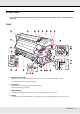
Printer Parts Your product may look different from the illustrations in this guide, but the instructions are the same. Front 1 Maintenance cover (left) Open this cover to clean the area around the print head. It is normally closed when the printer is in use. See “Cleaning Around the Print Head” on page 91. 2 After heater The after heater can be used to rapidly dry ink after printing. See “Heating & Drying” on page 68.
5 Roll core holder Place an empty roll core for media take-up on these holders. There are two holders: one on the left and one on the right. See“Media Loading and Take-Up” on page 48. 6 Roll core holder locking screw The locking screws keep the roll core holders in place once they have been attached to the roll core. There are two locking screws: one on the left and one on the right. 7 Roll support Rest media temporarily on these supports when removing the take-up roll.
21 Chip unit check lamp This lamp turns on when a message related to the chip unit is displayed. On: An error occurred. Check the message on the control panel’s screen. Off: No error. 22 AC inlets #1 and #2 Connect the power cables. Make sure you connect both cables. 23 LAN port See “LAN port” on page 13. 24 USB port Connects the USB cable. 25 Maintenance cover (right) Open this cover to perform maintenance around the print head. Normally closed when using the printer.
Slider (chip holder) 1 Slider Attach the chip unit included with the ink pack before refilling the ink. See “Chip Unit Replacement and Ink Refills” on page 104. 2 Ink inlet cover Open this cover to refill the ink tank with ink. 3 Chip unit A unit that includes an IC chip. This is included with the ink pack.
LAN port 1 RJ-45 connector Connects the LAN cable. Use a shielded twisted pair cable (category 5 or higher). 2 Data lamp (orange) Indicates the network connection status and whether the printer is receiving data. On: Connected Flashing: Receiving data 3 Status lamp (green/red) The color indicates network connection speed.
Interior Dirt on any of the following parts may reduce print quality. Regularly clean or replace these parts as described in the chapters listed in the reference sections below. 1 Print head The print head prints by moving left and right while emitting ink. Cleaning may be required. See “Cleaning Around the Print Head” on page 91. 2 Media holding plate The media holding plates prevent the media from riding up and keep fuzz on the cut edge of the media from touching the print head.
7 Caps Except during printing, these caps cover the print head nozzles to prevent them from drying out. Cleaning may be required. See “Part Cleaning” on page 89. 8 Wiper The wiper removes ink from the print head nozzles. Cleaning or replacement may be required. See “Part Cleaning” on page 89 See “Replacing the Wiper and Wiper Cleaner” on page 101. Back 1 Drive switch The drive switch is used to feed the media during loading and to rewind the media for replacement.
7 Handle After placing media on the right roll holder, rotate the handle to apply pressure to the roll core. Control Panel 1 P button (power button) Turns the power on and off. 2 P light (power light) The printer's operational status is indicated by a lit or flashing light. On: The power is on. Flashing: The printer is receiving data or performing head cleaning or other operations during shut-down. Off: The power is off.
3 M button (media setup button) Press this button to display the Media Setup menu, which contains such items as Media Remaining, Select Media, Customize Settings, and Print Media List. This button is disabled during printing. See “The Media Setup Menu” on page 119. 4 Display Displays the printer's status, menus, error messages, and so on. See “Understanding the Display” on page 18. 5 Menu button Press this button to display menus. See “Using the Control Panel Menu” on page 114.
12 W button (pause/cancel button) The printer enters pause status if this is pressed while printing. To release the pause status, press the W button again, or select Pause Cancel on the screen and then press the Z button. To cancel print jobs being processed, select Job Cancel on the screen and then press the Z button. Pressing this button when menus are displayed closes the menus and returns the printer to ready status.
3 Media info If a media setting bank number created with this printer is selected as the print media, the number (from 1 to 30) will be displayed. When RIP Settings is selected, 0 will be displayed. The selected platen gap is shown as follows. 1.5 2.0 2.5 The media remaining is not displayed if Off is selected for Remaining Setup in the Media Remaining menu. See “The Media Setup Menu” on page 119. 4 Chip unit status The display changes as shown below when an error is detected in the installed chip unit.
5 Waste ink bottle status Displays the approximate amount of space available in the waste ink bottle. The display changes as shown below when the waste ink bottle is nearly full or an error occurs . Normal Warning or error 1 1 Status indicators The status of the waste ink bottle is shown as follows. No error. The indicator changes to show the amount of space available. The waste ink bottle is almost full. Ready a new waste ink bottle. The waste ink bottle is full. Replace with a new waste ink bottle.
Features This wide-format color ink jet printer supports roll media up to 1626 mm (64 inches) in width. The main features of this printer are described below. Realizing High Productivity Improved Drying Characteristics The printer is equipped with an after heater that can be used to rapidly dry ink after printing. Media Feeding Unit Accommodates High-Capacity Rolls The standard media feeding unit can handle high-capacity rolls with external diameters of up to 250 mm (9.
Ease of Maintenance Print quality can only be ensured through daily maintenance, and the printer is constructed with this in mind. Lamp and Alarm Error Alerts When an error occurs, an alarm will sound and the alert lamp will light. The large alert lamp is highly visible, even at a distance. An alarm sounds simultaneously to prevent time wasted while stoppages due to errors go unnoticed.
Notes on Usage and Storage Installation Space Make sure that you secure the following space, clear of any other objects, so that paper ejection and consumable replacement are not obstructed. For the external dimensions of the printer, see “Specifications Table” on page 175. 100 mm (3.9 in.) 500 mm (19.7 in.) 1750 mm (68.9 in.) 1000 mm (39.4 in.) 3620 mm (142.5 in.) mm 00 in.) 10 9.4 (3 2903 mm (114.3 in.) 500 mm (19.7 in.
❏ We recommend performing maintenance on the following components as required. Failure to perform appropriate maintenance will shorten print head life. See “Maintenance Around the Print Head” on page 88. Component to be cleaned Frequency Print head When colors in the printout are faint or missing even after head has been cleaned. Wiper When the printout is smudged or not clear.
Head cleaning will be performed automatically after the printer is turned on. Head cleaning helps maintain print quality. Do not turn the printer off until cleaning is complete. Leaving the printer for too long without turning it on may result in a malfunction. Repair work for such malfunction will be charged. ❏ If you will not be using the printer for more than 2 weeks, maintenance must be performed by a service engineer before and after this period. This maintenance work will be charged.
Notes on Handling Ink Packs and Ink Tanks Note the following points when handling ink packs and ink tanks. ❏ Do not remove the ink tanks Ink tanks are calibrated when installed. Removing them can harm quality and functionality. ❏ Store ink packs at room temperature out of direct sunlight.
❏ Packaging materials can be used to store media and should not be thrown away. ❏ Avoid locations that are subject to direct sunlight, excessive heat, or humidity. ❏ When not in use, media should be removed from the printer, rewound, and inserted in its original packaging for storage. Leaving media in the printer for extended periods may cause it to deteriorate. Handling Media After Printing To maintain long lasting, high quality print results, note the following points.
Software Name Summary EPSON LFP Remote Panel 2 EPSON LFP Remote Panel 2 is used to update firmware from a computer and copy the media settings bank created in the printer’s setup menu to a computer. See “Starting EPSON LFP Remote Panel 2” on page 28 and “Exiting EPSON LFP Remote Panel 2” on page 28. Epson Drivers and utilities Install the Epson communications driver (EPSON SC-F7100 Series Comm Driver).
Uninstalling Software Important: ❏ Log in as an administrator. ❏ Enter the administrator password when prompted and then proceed with the remainder of the operation. ❏ Exit any other applications that may be running. This section describes how to uninstall EPSON LFP Remote Panel 2 and the Epson communications driver. 1. Turn off the printer, and unplug the interface cable. 2. Go to the Control Panel and click Uninstall a program from the Programs category. 3.
Chapter 2 Basic Operations Loading and Exchanging Media c Caution: ❏ Be careful not to trap your hands or fingers when opening or closing the front cover. Failure to observe this precaution could result in injury. ❏ Secure the media in place by the following procedure. Injury may occur if the media falls. ❏ Do not rub your hands along the edges of the media. The edges are sharp and can cause injury. Note: For information on the media that can be used in the printer, see “Supported Media” on page 163.
Important: ❏ Load media immediately before printing. The pressure rollers may crease media left in the printer. The media may also become wavy or curled, causing jams or resulting in the media coming into contact with the print head. ❏ If the following points are not observed when handling media, small amounts of dust and lint may stick to the media surface and cause in ink drops in the prints. ❏ Do not place exposed media directly on the floor.
c Caution: ❏ The after heater may be hot; observe all necessary precautions. Failure to observe the necessary precautions could result in burns. ❏ Because the media is heavy, it should not be carried by one person. When loading or removing the media, use at least two persons. 1. Remove the media holding plates, if installed. 2. Turn on the printer by pressing the P button. 3. Loosen the roll holder fixing screws and adjust the roll holders so that the gap between the two is wider than the media.
Important: If the right holder handle shaft is not visible, rotate the handle forward until it stops. The media can not be properly loaded if the handle shaft is not visible. 4. Place media on the roll support oriented according to how it is rolled (see below) and position it as indicated by the mark on the label.
If the label does not have a loading position, mark it on the label as instructed in the Setup Guide. Note: Be sure the option selected for Roll Type in the Customize Settings menu matches how the media is rolled. Roll Type defaults to Printable Side Out. Be sure to select Printable Side In after loading media rolled printable side in. For more information see “Roll Type” on page 70. 5.
7. Raise the roll holder lever on the right side of the printer to lift the media into position, then firmly insert the roll holder. If the roll of media has an outer diameter which is less than 140 mm (5.5 inches), lift it up by your hands, and place it on the roll holder as described in step 5. 8. To ensure that the roll holder is inserted into the roll core sufficiently, push the center section on the side of the roll holder toward the roll end.
9. Tighten the roll holder screw to fix the roll holder in place. Important: If the roll holder fixing screw is loose, the roll holder may move during printing. This could cause stripes and unevenness in the prints. 10. Rotate the handle until part A in the illustration below is fully inserted. Important: Once part A is hidden, do not turn the handle any further. Failure to observe this precaution could damage the roll holder.
11. Confirm that the right and left edges of the attached roll are aligned, and realign them if necessary. 12. Raise the media loading lever. 13. Pull out the edge of the media and insert it into the printer.
Note: Media that is heavy and difficult to unroll can be fed by pressing the drive switch on the left roll holder. Printable side out Printable side in 14. Insert the media past the pressure rollers and lower the media loading lever to hold it in place. Confirm that the left edge of the media passes over the center of the square in the label on the loading guide. Important Perform steps 14 to 4 in reverse order and repeat the loading process if the left edge of the media is not within the guides.
15. Go to the front of the printer and open the front cover. 16. Hold the center of the media and raise the media loading lever. 17. Pull the media straight forward to the leading edge of the after heater. 18. Close the front cover. 19. Rewind the leading edge of the media to the front cover. For media with the printable side out, press the u button. For media with the printable side in, press the d button.
Confirm that the paper was fed straight with the media straight and taut. Note: We recommend using the r button on the control panel to set Media Suction to 2, which helps to ensure that the media is rewound straight. 20. Open the front cover. 21. Lower the media loading lever to hold the media in place. 22. Attach the media holding plates.
First, position the plates so that the edges of the media are in the centers of the round holes. Important: Always position the plates so that the edges of the media are at the centers of the round holes. Incorrect positioning causes banding (horizontal banding, lines, or strips of uneven color) during printing.
23. Align the white lines of the plates with the white lines of the platen and push the plates down to lock them in place and keep them from lifting. Important: ❏ Do not use the media holding plates with media that is more than 0.4 mm (0.02 inch) thick. The media holding plates could touch and damage the print head. ❏ Move the media holding plates to the left and right edges of the platen when they are not in use. ❏ Do not use the media holding plates if the sides of the printed media are smudged or torn.
Viewing and Changing Media Settings The control panel displays the following information once the media is loaded. This display can be used to view or change the following two options: ❏ Remaining Setup On: The printer displays the amount of media remaining. Off: The printer does not display the amount of media remaining.
See “Saving Settings” on page 66. 1. Select an option. To print with current settings: Use the d/u buttons to select Keep Settings Above and press the Z button. Proceed to step 6. To change settings: Use the d/u buttons to select Change Settings and press the Z button. 2. Select the items you want to change and press the Z button. 3. Select the desired option and press the Z button. 4. Press the y button to display the dialog shown in step 2 and then press the y button again. 5.
Exchanging Media To replace the media after printing, print the amount of media remaining, cut the media, and remove the roll. Printing the Amount of Media Remaining The printer displays the amount of media remaining and any media low warnings in the control panel. This makes it possible to determine whether the media requires replacement before printing. The amount of media remaining can only be displayed if the correct length is entered when the media is loaded.
4. Press the Z button to print the amount of media remaining. Cutting Media Use a cutter (not included) to cut the media when printing is complete. This section described how to use a cutter to cut the media. c Caution: ❏ The after heater may be hot; observe all necessary precautions. Failure to observe the necessary precautions could result in burns. ❏ When cutting media, be careful not to cut your fingers or hands with the cutter or other blades. 1. Confirm that the printer is ready to print. 2.
If you have printed the amount of media remaining, press the u button to rewind the media so that this information will remain on the roll after the media is cut. 3. Remove the media holding plates. 4. Cut the media with the cutter. Pass the blade of the cutter down the cutting groove.
Important: To continue printing after cutting, do not rewind the media past the cutter groove (on the pressure roller side). If the leading edge of the media is curled, stop rewinding before the media reaches the inner side of the front cover. Note: If you are using the auto take-up reel unit, set the Auto switch on the auto take-up reel unit to Off before using the Manual switch to position the media over the cutting groove. Removing Media You can now remove the media from the roll holders.
c Caution: ❏ Be sure that your hands or hair do not get caught in the auto take-up reel unit while it is in operation. Failure to observe this precaution could result in injury. ❏ Perform the following procedure to correctly secure the roll core for the auto take-up reel unit into place. Injury may occur if the take-up roll falls. Important: ❏ We recommend using a take-up roll core with the same width as the media.
2. After confirming that the media is loaded correctly, press the d button to feed the media as far as the auto take-up reel unit roll core holder. Important: Always press the d button to feed the media as far as the roll core holder. If the media is pulled by hand, the media may twist during take-up. 3. Loosen the roll core holder locking screws and adjust the roll core holders so that the gap between the two is wider than the media. Center the roll supports between the roll holders.
4. Align the right roll core holder with the right edge of the media and tighten the locking screw. 5. Insert the roll core onto the right holder. 6. Confirm the following: the left roll core holder is fully inserted into the roll core, and the roll core and edges of the media are not misaligned. Important: If the edges of the media are misaligned, the media cannot be taken up correctly. To correct misalignment, loosen the right roll core holder locking screw, and then restart from Step 4. 7.
Confirm that the roll core and edges of the media are not misaligned. Important: Stop when part A is no longer visible. The take-up reel unit may not function as expected if the holder is inserted too far. 8. Tighten the roll core holder locking screw to fix the roll core holder in place.
9. Rotate the handle until part A in the illustration below is fully inserted. Important: Once part A is hidden, do not turn the handle any further. Failure to observe this precaution could damage the roll core holder. If part A is not hidden even after turning the handle until it can no longer be turned, the roll core holder may not be fully inserted. Return to step 6. For information on take-up with the printed side out, see the following section.
In the order shown in the illustration, tape the media to the take-up roll core. When attaching in the center, tape while pulling the center of the media straight. When attaching on the left and right, tape while pulling the media sideways. Important: If the media is lifted up between the attached pieces of tape, the media will not be taken up correctly. We recommend either adding tape and attaching it uniformly or fixing creases at the leading edge of the media. 2.
3. Flip the Manual switch to to wrap the media once around the roll core. 4. Confirm that the media is not loose.
Confirm differences in tension on the right and left by lightly tapping on both edges of the media. Important: As shown in the identified sections in the illustration below, if the tension of the left and right edges of the media are different, the media that follows cannot be taken up correctly. If there is slack on one side, flip the Manual switch to to rewind the media, remove the tape, and then restart from Step 1.
5. Confirm that the edges of media taken up on the roll core are not misaligned. Important: If the edges of media taken up on the roll core are misaligned, the media that follows cannot be taken up correctly. When misaligned, rewind the media, remove the tape, and then restart from Step 1. 6. Flip the Auto switch to .
Take-Up With the Printed Side Facing In 1. Pass the media under the media guide bar, and then attach the media to the take-up roll core. In the order shown in the illustration, tape the media to the take-up roll core. When attaching in the center, tape while pulling the center of the media straight. When attaching on the left and right, tape while pulling the media sideways. Important: If the media is lifted up between the attached pieces of tape, the media will not be taken up correctly.
3. Flip the Manual switch to to wrap the media once around the roll core. 4. Confirm that the media is not loose.
Confirm differences in tension on the right and left by lightly tapping on both edges of the media. Important: As shown in the identified sections in the illustration below, if the tensions of the left and right edges of the media are different, the media that follows cannot be taken up correctly. If there is slack on one side, flip the Manual switch to to rewind the media, remove the tape, and then restart from Step 1.
5. Confirm that the edges of media taken up on the roll core are not misaligned. Important: If the edges of media taken up on the roll core are misaligned, the media that follows cannot be taken up correctly. When misaligned, rewind the media, remove the tape, and then restart from Step 1. 6. Flip the Auto switch to .
Removing the Take-up Roll c Caution: ❏ Because the media is heavy, it should not be carried by one person. When loading or removing the media, use at least two persons. ❏ Perform the following procedure to properly remove the take-up roll. Injury may occur if the take-up roll falls. 1. Set the Auto switch to Off. 2. Cut the media and roll the cut end onto the take-up reel. See “Cutting Media” on page 46. 3. Rotate the handle of the left roll core holder.
4. To prevent the media from sliding off the roll, support the roll at its left end. 5. Loosen the left roll core holder locking screw and remove the roll core holder from the roll. 6. Lower the roll onto the roll support. 7. To prevent the media from sliding off the roll, support the roll at its right end. 8. Loosen the right roll core holder locking screw and remove the roll core holder from the roll.
9. Lower the roll onto the roll support. Before Printing To maintain print quality, perform the following inspection before starting work each day. ❏ Print a check pattern to check for clogged nozzles. ❏ Perform head cleaning if parts of the pattern are faint or missing. See “Checking for Clogged Nozzles” on page 84. See “Head Cleaning” on page 86.
Parameters Stored in Media Setting Banks Media setting banks store the following: ❏ Setting Name ❏ Feed Adjustment ❏ Platen Gap ❏ Head Alignment ❏ Heating & Drying ❏ Media Suction ❏ Head Movement ❏ Multi-Strike Printing ❏ Roll Type ❏ Tension Measurement ❏ Feeding Tension ❏ Take-up Tension ❏ Feed Speed For more information on these items, see “The Media Setup Menu” on page 119.
Saving Settings Follow the steps below to save media settings. Choosing a Media Setting Bank 1. After confirming that the printer is ready to print, press the Menu button. The settings menu will be displayed. 2. Select Media Setup and press the Z button. 3. Use the d/u buttons to select Customize Settings and press the Z button. 4. Use the d/u buttons to select a media setting bank number between 1 and 30 and then press the Z button. Note that any settings already saved to the printer will be overwritten.
3. After entering the name, press the Z button. Feed Adjustment (manual) Feed Adjustment is used to correct banding (horizontal banding, lines, or strips of uneven color). You need to visually inspect prints and enter a correction by hand. For more information on feed adjustment, see “Feed Adjustment” on page 76. Platen Gap Adjust the platen gap (the gap between the print head and the media) if prints are smudged. 1. Use the d/u buttons to select Platen Gap and press the Z button. 2.
Heating & Drying Set the temperature of the after heater. Note: Adjust Heater Temperature as follows: ❏ Set the heater to the temperatures recommended in the documentation provided with the media, if available. ❏ Raise the temperature if the prints are blurred or smudged or the ink clots. Note, however, that raising the temperature too high can cause the media to shrink, wrinkle, or deteriorate. 1. Use the d/u buttons to select Heating & Drying and press the Z button. 2.
Recommended setting values for Blank Area Feed Number of passes Blank Area Feed 1 Mode 1 2 to 4 Mode 2 5 to 8 Mode 3 After Heater Feed (1) Use the d/u buttons to select After Heater Feed and press the Z button. (2) Use the d/u buttons to select whether to feed media to the after heater after printing (On/Off). 3. After finishing the configuration, press the Z button. 4. Press the y button twice to return to the customize settings menu.
1. Use the d/u buttons to select Multi-Strike Printing and press the Z button. 2. Use the d/u buttons to choose a value. 3. Select the desired option and press the Z button. 4. Press the y button to return to the customize settings menu. Roll Type Choose Printable Side Out or Printable Side In according to how the media is rolled. 1. Use the d/u buttons to select Roll Type and press the Z button. 2. Use the d/u buttons to select the desired setting and press the Z button. 3.
If you have previously performed Feed Adjustment, you will need to perform it again after adjusting Media Tension. See “Feed Adjustment (manual)” on page 67. 1. Use the d/u buttons to select Feeding Tension and press the Z button. 2. Use the d/u buttons to select the item you want to change. Selecting Auto (1) Select Auto and press the Z button. (2) Confirm that the checkbox has been selected and press the Z button. (3) Press the y button to return to the customize settings menu.
(3) After finishing the configuration, press the Z button. (4) Press the y button twice to return to the customize settings menu. Feed Speed Choose a slower feed speed if media is creased or torn or sticks together during printing. The lower the value, the slower the speed. 1. Use the d/u buttons to select Feed Speed and press the Z button. 2. Use the d/u buttons to choose a value. 3. Select the desired option and press the Z button. 4. Press the y button to return to the customize settings menu.
Use the following procedure. Note: ❏ Temperature settings can be stored separately for each media type. See “Saving Optimal Settings for the Current Media (Print Media Settings)” on page 64. ❏ The time needed for the heaters to reach the specified temperatures varies with the ambient temperature. 1. After checking that the printer is ready, press the Drying menu. button to display the Heating & 2. Use the d/u buttons to select the desired option and press the Z button. 3. Choose a value.
In Head Alignment, you can select the following adjustment methods. ❏ Manual(Uni-D) Select for unidirectional printing. ❏ Manual(Bi-D) Select for bidirectional printing. For Head Alignment, you need to check the pattern and enter the optimum adjustment value for alignment. Notes on correct adjustment: The condition of media is important for correct head alignment. Observe the following points when loading media. ❏ Head Alignment varies with the media being used.
5. Use the d/u buttons to select a media setting bank number between 1 and 30 and then press the Z button. Note that any settings already saved in the printer will be overwritten. 6. Use the d/u buttons to select Head Alignment and press the Z button. 7. Use the d/u buttons to select Manual(Uni-D) or Manual(Bi-D) and press the Z button. 8. An alignment pattern will be printed. When printing is complete, the media will automatically be fed to a position where the pattern is clearly visible.
Note: To rewind the media, press the u button. Stop rewinding before the media is past the cutter groove (on the pressure roller side). If the leading edge of the media is curled, stop rewinding before the media reaches the inner side of the front cover. 12. When the final color has been configured, the printer returns to a ready state. Feed Adjustment Feed Adjustment is used to correct banding (horizontal banding, lines, or strips of uneven color).
Using a Test Pattern 1. Confirm that the media has been pulled to the prescribed position. Correct adjustment may not be possible if the media is not pulled sufficiently. See “Loading and Exchanging Media” on page 30. 2. After confirming that the printer is ready to print, press the Menu button. The settings menu will be displayed. 3. Select Media Setup and press the Z button. 4. Use the d/u buttons to select Customize Settings and press the Z button. 5.
10. Using a ruler that shows millimeters, measure the distance between the “+” symbols. Use values measured at #1 and #2. 11. Pattern length is displayed on the control panel. Select the values measured in Step 10. Use the l/r buttons to select the number of #1 and press the Z button. Use the l/r buttons to select the number of #2 and press the Z button. 12. If configuration is finished, the printer returns to a ready state.
Performing Feed Adjustment During Printing Feed adjustment during printing is recommended for minor banding issues. 1. Press the button during printing. 2. An adjustment value will be displayed. Use the d/u buttons to select a value. If the feed amount is too small, black bands (dark stripes) will appear; adjust the feed amount upwards. If, in contrast, the feed amount is too large, white bands (pale stripes) will appear; adjust the feed amount downwards. 3.
Printable area The gray area in the illustration below shows the printable area. The arrow indicates the feed direction. The positions of items 1 to 2 are as follows: 1 (right edge of media) On selected for Media Size Check: The right edge of the media. Off selected for Media Size Check: Right edge reference position *1 2 (left edge of media) On selected for Media Size Check: The left edge of the media.
*2 When media holding plates are attached, within 5 mm (0.2 inch) of the left and right edges of the media is recognized as the media edge. For example, if the Side Margin is set to 5 mm (0.2 inch), the actual margin is 10 mm (0.4 inch). Note that if the media holding plates are attached incorrectly, this value fluctuates. See “Loading Media” on page 31. *3 The value when jobs are printed continuously. Differs by the length the media was pulled when the media is loaded.
Chapter 3 Maintenance Daily Maintenance To maintain print quality, perform the following inspection and cleaning before starting work each day. Cleaning the Platen, Pressure Rollers, and Media Holding Plates c Caution: ❏ The after heater may be hot; observe all necessary precautions. Failure to observe the necessary precautions could result in burns. ❏ Be careful not to trap your hands or fingers when opening or closing the front cover. Failure to observe this precaution could result in injury.
Remove particles of paper and dust from the pressure rollers using a soft-bristled brush. 6. Clean the media holding plates and platen. Dampen a soft cloth in water, wring it out thoroughly, and use it to remove lint and dust from the media holding plates on both the left and right sides and from the platen.
Checking for Clogged Nozzles We recommend that you check the nozzles for clogs each time you print to ensure quality results. Ways to Check for Clogs There are two ways to check for clogs. ❏ Print Nozzle Pattern At specified intervals, the printer prints a test pattern at the start of normal printing. When printing is complete, you can visually inspect the pattern to determine whether there may be faint or missing colors in the preceding or following printout. See “The Printer Setup Menu” on page 124.
This section explains how to print and inspect a check pattern. 1. After confirming that the printer is ready, press the # button. The Maintenance menu will be displayed. 2. Select Nozzle Check, select a print position, and press the Z button. 3. A nozzle pattern will be printed. 4. Inspect the nozzle pattern. Example of clean nozzles: The pattern contains no gaps. Example of clogged nozzles: Perform head cleaning if any segments are missing from the pattern. See “Head Cleaning” on page 86.
Always remove clogs from the nozzles of all colors before resuming use. If clogged nozzles (including clogged nozzles for colors that are not used) remain after resuming use, the clogs can no longer be removed. 5. The menus close when printing is complete. If you will use the margin of media on which a check pattern has been printed, use the u button to rewind the media until the Print Start Position reaches the position of the pressure roller.
❏ Cleaning Cycle Head cleaning is performed automatically at selected intervals of 1 to 10 pages. See “The Printer Setup Menu” on page 124. This section explains how to clean the head if you find that the nozzles are clogged on printing a test pattern. 1. Pressing the # button when the printer is ready to print displays the Maintenance menu. Pressing the # button when printing is paused takes you to step 3. 2. Use the d/u buttons to select Cleaning and press the Z button. 3.
❏ Use the d/u buttons to choose the nozzle arrays with faint or missing segments in the nozzle check pattern and press the Z button. ❏ After selecting the arrays you wish to clean, select Proceed and press the Z button. 5. Select a cleaning level and press the Z button. Select Execute (Light) first. The menu will close when cleaning is complete. Print a nozzle pattern and inspect the results to determine whether the problem has been resolved. See “Checking for Clogged Nozzles” on page 84.
❏ A metal or plastic tray made from polypropylene (PP) or polyethylene (PE) (not included) Used cleaning sticks, wipers, and wiper cleaners taken from the printer can be placed here. Notes on Cleaning ❏ Remove the media from the printer before proceeding. ❏ Complete the task within 10 minutes to prevent the print head drying out. An alarm will sound after 10 minutes. ❏ Never touch the belts, circuit boards, or any parts that do not require cleaning.
(3) Caps (4) Wiper rail Moving the Print Head This section describes how to position the print head for part cleaning. Important: Be sure to follow the steps below when positioning the print head. Moving the print head manually could cause malfunction. 1. Confirm that the printer is on and press #. The Maintenance menu will be displayed. 2. Use the d/u buttons to select Head Maintenance and press the Z button. 3. Press the Z button to move the print head to the part cleaning position. 4.
Cleaning Around the Print Head Inspect the area around the print head and remove any ink stains as described below. 1. Use a cleaning stick to wipe areas 1 and 2. Important: Be sure to use a narrow cleaning stick to clean between the nozzles (the areas shown in the illustration). Do not touch the nozzle surface. Touching the nozzle surface with the cleaning stick could damage the print head. 1 Nozzle area: Clean as shown in the illustration. 2 Other areas: Wipe adhered ink, lint, and dust.
2. Ink spatters on the base of the print head can be removed using a clean room wipe (not included). Important: ❏ Be sure not to touch the nozzle surface during cleaning. Failure to observe this precaution could damage the print head. ❏ The parts shown below are sensors. Be careful not to touch this area with your hands or clean room wipes. Failure to observe this precaution could affect print quality. Cleaning the Wiper and Caps 1. Clean the front and back of the wiper with a cleaning stick.
If there is ink on the attachment points, remove the wiper for cleaning. Proceed to step 2. 2. Remove the wiper. Holding the wiper by the attachment point, tilt it to the left and lift it out.
3. Clean the front and back of the wiper with a cleaning stick. 4. Clean the bottom of the wiper with a cleaning stick. 5. Clean the attachment points with a cleaning stick. 6. Return the wiper when cleaning is complete.
Place the wiper on the attachment point and press it down until it clicks into place. 7. Clean the area around the outside of the caps with a cleaning stick. Important: Do not touch the insides of the caps. Failure to observe this precaution could deform the affected parts. Cleaning the Wiper Rail Important: Neglecting to clean the wiper rail can impair the performance of the wiper, causing product malfunction. 1.
2. Remove the wiper cleaner. Grasp the cleaner as shown and lift it from the printer. 3. Clean the area shown in the illustration. 4. Return the wiper cleaner that was removed in Step 2 to its original position.
Place it on the attachment point and press down until you hear a click. 5. Close both maintenance covers and press the Z button. The menus will close when the print head returns to its normal position. Disposing of Waste Ink When to Dispose of Waste Ink Be sure to replace the waste ink bottle when the following message is displayed on the control panel. ❏ Prepare empty waste ink bottle. ❏ Replace waste ink bottle and press Z.
c Caution: ❏ Store waste ink in a location out of reach of children. ❏ Wear protective eyewear and gloves when replacing waste ink bottle. ❏ Should waste ink contact your skin or enter your eyes or mouth, immediately take the following actions: ❏ If fluid adheres to your skin, immediately wash it off using large volumes of soapy water. Consult a physician if the skin appears irritated or is discolored. ❏ If fluid enters your eyes, rinse immediately with water.
Replacing the Waste Ink Bottle 1. Raise the stopper. 2. Remove the waste ink bottle from the waste ink bottle holder.
Note: If the underside of the stopper is stained, wipe it. 3. Insert the waste ink tube into the mouth of the new waste ink bottle and place the waste ink bottle in the holder. Tightly seal the lid on the used waste ink bottle. Important: ❏ Be sure to confirm that the waste ink tube is inserted in the mouth of the waste ink bottle. Ink will spill onto the surrounding area if the tube is not inserted in the bottle. ❏ You will need the lid for the waste ink bottle when disposing of waste ink.
Replacing the Wiper and Wiper Cleaner Replace the wiper and wiper cleaner if the printout is faint or smudged or segments are missing even after cleaning. 1. Confirm that the printer is on and press #. The Maintenance menu will be displayed. 2. Use the d/u buttons to select Head Maintenance and press the Z button. 3. Press the Z button to move the print head to the cleaning position. 4. Open the right maintenance cover. 5. Remove the wiper cleaner.
Grasp the cleaner as shown and lift it from the printer. 6. Insert a new wiper cleaner. Place the wiper cleaner on the attachment point and press down until you hear a click. 7. Remove the wiper.
Holding the wiper by the attachment point, tilt it left and lift it out. 8. Insert new wiper. Remove the cap on the wiping part of the wiper, then place the wiper on the attachment point and press down until you hear a click. 9. Press the Z button when the replacement procedure is complete. 10. Close the maintenance cover and press the Z button. The menus will close when the print head returns to its normal position.
Chip Unit Replacement and Ink Refills Time Period for Chip Unit Replacements and Ink Refills If the message Chip unit expended is displayed on the control panel, this means that the chip unit needs to be replaced soon. Obtain an ink pack of the appropriate color as soon as possible. You will be unable to print if the chip unit for even one color needs to be replaced. If the Chip unit expended message is displayed during a print job, you can replace the chip unit and refill the ink while printing continues.
Procedure for Chip Unit Replacement and Ink Refills You can use the same procedure to replace chip units for all colors. c Caution: ❏ Store ink packs in a location out of reach of children. ❏ Wear protective eyewear and gloves when refilling ink. Be sure to read the Material Safety Data Sheet (MSDS) before using ink packs. You can download it at your local Epson Web site.
Important: ❏ Epson recommends the use of genuine Epson ink packs. Epson cannot guarantee the quality or reliability of non-genuine ink. The use of non-genuine ink may cause damage that is not covered by Epson’s warranties, and under certain circumstances, may cause erratic printer behavior. Information about non-genuine chip unit status may not be displayed, and use of non-genuine ink is recorded for possible use in service support.
Important: When the remaining ink is 70 mm (2.8 inches) or more from the bottom of the ink tank and a message appears stating, Refill Ink Tank, it is time to replace the ink tank. We recommend replacing the ink tank at this time. Replacements and repairs will be provided for a fee. During replacements and repairs, the ink in the ink tank is discarded. This is necessary because fine dirt, dust, and other foreign bodies in the ink cause the ink tank to malfunction.
4. Remove the chip unit from the slider. 5. Attach the chip unit supplied with the new ink pack to the slider. Check to confirm that the color of the label on the slider matches the color of the label on the chip unit when installing.
6. Hold the slider level and insert it, then lower the lock lever. Important: Do not push the slider in with too much force. Failure to observe this precaution could damage the printer. 7. Shake the new ink pack horizontally for approximately 5 cm (2 inches) left and right for 5 seconds (approximately 15 times).
8. Open the slider ink inlet cover. 9. Remove the ink inlet cap from the ink tank. 10. Cut or tear off the ink pack spout opening. 11. Fill the ink tank with the ink from the ink pack.
Insert the spout of the ink pack into the ink tank ink inlet groove and slowly tilt to pour out the ink. Important: Get all the ink out of the ink pack so that there is none remaining. Do not use the ink in an ink pack to refill multiple ink tanks. This can prevent the proper display of messages from the remaining ink warning system.
12. Put the ink inlet cap back on the ink tank. 13. Close the slider ink inlet cover. Disposal of Used Consumables Dispose of used ink packs and chip units, as well as printed media following local laws and regulations, for example by consigning waste to industrial waste disposer.
Parts That Are Periodically Replaced The following parts require periodic replacement. The time until the following parts need to be replaced depends on the conditions of use: ❏ Print head ❏ Ink holder ❏ Damper kit ❏ Pump cap ❏ Ink supply tank The part life varies with operating conditions. Base the decision to replace the print head on the quality of the prints.
Chapter 4 Using the Control Panel Menu Menu Operations The menus are used as shown below.
Menu List The following items and parameters can be set and executed in the Menu. See the reference pages for more details on each item. Menu Item Media Setup Media Remaining See “The Media Setup Menu” on page 119. Parameter Remaining Setup On, Off Length 5.0 to 99.
Menu Item Parameter 1 to 30 (media setting bank number) Setting Name Up to 22 half-size characters Feed Adjustment Manual Platen Gap 1.5, 2.0, 2.
Menu Item Parameter Printer Setup Side Margin(Right) 3 to 25 mm (0.12 to 1.00 inch) See “The Printer Setup Menu” on page 124. Side Margin(Left) 3 to 25 mm (0.12 to 1.00 inch) Print Start Position 0 to 800 mm (0.00 to 32.00 inches) Media Size Check On, Off Media End Check On, Off Media Skew Check On, Off Print Nozzle Pattern Off, 1 to 10 pages Periodical Cleaning Light Off, 1 to 240 hours Medium Heavy Power Maintenance See “The Maintenance Menu” on page 126.
Menu Item Network Setup IP Address Setting See “The Network Setup Menu” on page 128. Parameter Auto - Panel IP: 000.000.000.000 – 255.255.255.255 SM: 000.000.000.000 – 255.255.255.255 DG: 000.000.000.000 – 255.255.255.255 Print Status Sheet Print Restore Settings Yes, No Preference Date And Time MM/DD/YY HH:MM See “The Preference Menu” on page 128.
Details of the Menu The Media Setup Menu The Media Setup menu can be accessed directly by pressing the M button. indicates default settings. Media Remaining Item Parameter Explanation Remaining Setup On Off Choose On to display and record, or Off to not display and not record, the amount of media remaining. Length, Remaining Alert, and Print Remaining Length options are available when On is selected.
RIP Settings Item Parameter Explanation Platen Gap 1.5 Change Platen Gap (the gap between the print head and the media) for the media setting bank selected in the software RIP. 2.0 2.5 The default setting of 2.0 is recommended in most situations. Choose 1.5 if print quality is unsatisfactory. Choose 2.5 if printout is scratched or smudged. Choosing a larger gap than required may result in ink stains inside the printer, reduced print quality, or shorter product life.
Item Parameter Explanation Restore Settings Yes If Yes is selected, the configured RIP Settings are returned to the default settings. No 1 to 30 (media setting bank number) Item Parameter Setting Name Feed Adjustment Explanation Assign the media setting bank a name up to 22 half-size characters long. Using distinctive names makes it easier to select banks for use.
Item Parameter Explanation Media Suction 0 to 10 Suction is required to maintain the correct distance between the media and the print head; the amount needed varies with the type of media. Excessive suction can increase the gap between the print head and thin or flexible media, potentially reducing print quality or preventing the media feeding normally. In such cases, you will need to lower media suction. The suction power is weakened when the parameter is lowered.
Item Parameter Explanation Auto - Manual 1 to 6 Auto is recommended in most situations. If Media Size Check is not On when Auto is set, the appropriate tension is not applied because the media width cannot be detected. If Media Size Check is Off, set Take-up Tension to Manual and then set the recommended value for the media width. If Take-up Tension is set to Auto and creases appear during printing or black bands (dark stripes) appear in the prints, set Take-up Tension to Manual.
The Printer Setup Menu indicates default settings. Item Parameter Explanation Side Margin(Right) 3 to 25 mm (0.12 to 1.00 inch) Choose the width of the right margin when media is loaded in the printer. For more information, see “Printable area” on page 80 Side Margin(Left) Print Start Position 3 to 25 mm (0.12 to 1.00 inch) Choose the width of the left margin when media is loaded in the printer. 0 to 800 mm (0.00 to 32.
Item Light Parameter Explanation Off/1 to 240 hours Choose the frequency—never (Off) or after 1 to 240 hours—and strength with which the printer performs head cleaning. Periodic head cleaning will not be performed while Off is selected. If a value between 1 and 240 hours is selected, auto head cleaning will be performed after the specified number of hours.
The Maintenance Menu The Maintenance menu can be accessed directly by pressing the # button. Item Parameter Explanation Nozzle Check Print A nozzle pattern will be printed. Inspect the pattern visually and perform head cleaning if you detect faint or missing colors. See “Checking for Clogged Nozzles” on page 84. Print At Right Print At Center The menu displayed depends on the Media Size Check setting and the width of the loaded media.
The Print Logs Menu These items are used to track consumables. Item Parameter Explanation Print Job Log Sheet Print You can print the job information saved in the printer (up to 10 jobs). The information includes the media and ink used in each job, making it easier to track the use of consumables. Notes on ink consumption: This is a simple tool for estimating ink consumption for a given print job. EPSON DOES NOT WARRANT ACCURACY.
The Network Setup Menu indicates default settings. Item Parameter Explanation Auto - Panel IP: XXX.XXX.XXX.XXX Choose whether IP addresses are obtained automatically (Auto) or manually (Panel) using DHCP. If Panel is selected, enter an IP address, subnet mask, and default gateway address. Contact your system administrator for detailed information. IP Address Setting SM: XXX.XXX.XXX.XXX DG: XXX.XXX.XXX.XXX Print Status Sheet Print Use Print Status Sheet to print the current network status.
Item Parameter Explanation Alert Sound Setting On Enable (On) or disable (Off) the alarm that sounds when an error occurs. If the alarm is sounding, press the OK button to turn it off. Off Alert Lamp Setting On Off Enable (On) or disable (Off) the alert lamp that lights when an error occurs. The Reset All Settings Menu Parameter Explanation Yes Select Yes to reset all settings in the Preference menu except Date And Time, Language, Unit: Length, and Unit: Temperature.
Chapter 5 Problem Solver When a Message Is Displayed If one of the following messages is displayed, read and follow the instructions below. Messages What to do Prepare empty waste ink bottle. The waste ink bottle is getting full. Ready a new waste ink bottle. See “Options and Consumable Products” on page 162. Chip Unit Error Chip unit not recognized. Reattach or replace. Remove and reinsert the chip unit. If the same error still occurs, replace with a new chip unit.
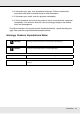
When a Maintenance Call/Service Call Occurs Error messages What to do Maintenance Request A part used in the printer is nearing the end of its service life. Contact your dealer or Epson Support and tell them the maintenance request code. You cannot clear the maintenance request until the part is replaced. A service call occurs if you continue to use the printer. Call For Service XXXX Error XXXX Power off and then on. If this doesn’t work, note the code and call for service.
o When using a USB hub, is it being used correctly? In the USB specification, daisy-chains of up to five USB hubs are possible. However, we recommend that you connect the printer to the first hub connected directly to the computer. Depending on the hub you are using, the operation of the printer may become unstable. If this should occur, plug the USB cable directly into your computer's USB port. o Is the USB hub recognized correctly? Make sure the USB hub is recognized correctly on the computer.
Test pattern does not print correctly o Perform head cleaning. The nozzles may be clogged. Print a test pattern again after performing head cleaning. See “Head Cleaning” on page 86. o Has the printer been left unused for a long time? If the printer has not been used for a long time, the nozzles may have dried up and have been clogged. Steps to take when the printer has not been used for a long time. See “Notes When Not Using the Printer” on page 24.
o Are media settings correct? Confirm that the media settings in the software RIP or on the printer match the media actually in use. o Is Data Width selected for Head Movement? Selecting Data Width for Head Movement in the setup menu increases print speed but may slightly reduce print quality. For better quality results, select Printer Full Width for Head Movement. See “The Printer Setup Menu” on page 124.
The printed surface is scuffed or soiled. o Is the media too thick or too thin? Check media specifications to confirm that it is compatible with the printer. If you are using a software RIP, contact the manufacturer for information on the settings and media that can be used. o Is the media wavy? Certain types of media may develop waves under some conditions (humidity and temperature) while installed in the printer.
Horizontal lines or strips of uneven color (banding) Multiple causes are possible. Perform the following sequence until the print results have improved. Before starting work, always perform a nozzle check and Head Alignment. If nozzles are clogged or the head is misaligned, no measures will result in improvements. See “Checking for Clogged Nozzles” on page 84 and “Correcting Print Misalignment (Head Alignment)” on page 73. 1. Check the attachment of the media holding plates.
Perform the following sequence until the print results have improved. 1. Cut sections of media with wrinkles or waviness. If media is stored inappropriately or left loaded in the printer, wrinkles and waviness may occur. If media is used in this state, the print head and the raised surface of the media may contact and cause staining. Cut sections with wrinkles or waviness before using media.
o Try selecting Off for Tension Measurement in the setup menus. Automatic tensioning may fail to maintain some types of media at the appropriate tension, resulting in excessive slack or other tensioning problems that interfere with printing. See “Tension Measurement” on page 70. Media jams o Is the media creased or folded? Media with a strong curl or that is folded back on its leading edge or creased may cause jams or other media feed problems. Do not use media affected by these types of problems.
3. Remove the media holding plates, if installed. Important: Cease use of the printer if the media holding plates are deformed. Continued use could damage the pressure rollers or print head. Contact Epson Support. See “Contacting Epson Support” on page 179. 4. If the print head is over the media, move it away from the jam. Important: Move the print head only after removing the media holding plates. Contact with deformed media holding plates could damage the print head. 5. Raise the media loading lever.
6. Pull the media to the cutter groove and use a cutter to remove torn or creased portions. 7. Manually rewind the cut media. 8. Remove any media that remains inside the printer. 9. Turn on the power to the printer and perform a nozzle check. Check the printed pattern, and if there are any clogs, perform head cleaning. See “Checking for Clogged Nozzles” on page 84.
Two hexagon wrenches are included with the printer. For parallel adjustment of the media feeding unit, use the large hexagon wrench. Parallel adjustment of the media feeding unit 1. Open the front cover and raise the media loading lever. 2. Face the rear side of the printer and loosen the 4 screws using the hexagon wrench.
3. Loosen the roll holder fixing screws and adjust the roll holders so that the distance between the two is wider than the roll core. 4. Tighten the roll holder fixing screw to align the left roll holder with the position of dotted line. 5. Insert the adjustment paper into the roll core.
6. Insert the roll core into the left roll holder. Insert the right roll holder into the roll core, and then tighten the roll holder fixing screw. Important: Insert the right roll holder into the roll core until part A in the illustration below cannot be seen.
7. Bring the adjustment paper to a position 5 cm (2 inches) from the right edge of the roll core, and then insert it into the printer.
8. At the front side of the printer, keep the adjustment paper taut, place a ruler on the front side of the white line on the platen, and then draw a line with a pen or other writing instrument. 9. Pull out the adjustment paper from the rear side, move it to a position 5 cm (2 inches) from the left edge of the roll core, and then insert it into the printer.
10. At the front side of the printer, keep the adjustment paper taut and check the positions of the white line on the platen and the line drawn in Step 8. If the drawn line and white line are misaligned as shown in the illustration below, proceed to Step 11. If they are aligned, proceed to Step 12. 11.
The adjustment is complete when the drawn line reaches the position of the dotted line. 12. Use the hexagon wrench to tighten and firmly secure the 4 screws.
13. Pull out the adjustment paper from the printer, loosen the right roll holder fixing screw, and move away the roll holder. 14. Pull out the roll core.
1. Use a hexagon wrench (large) to loosen the 4 screws. 2. Loosen the roll core holder locking screws and adjust the roll core holders so that the distance between the two is wider than the roll core. 3. Tighten the roll core holder locking screw to align the right roll core holder with the position of dotted line.
4. Insert the roll core into the right roll holder. Insert the left roll core holder into the roll core, and then tighten the roll core holder locking screw. Important: Insert the left roll holder into the roll core until part A in the illustration below cannot be seen, and then tighten the roll holder locking screw. 5. Move the adjustment paper to a position 5 cm (2 inches) from the left edge of the roll core, and then insert it into the printer.
Pass the adjustment paper behind the rear side of the media guide bar, and then insert it into the printer. 6. Pull out the adjustment paper, move it to a position 5 cm (2 inches) from the right edge of the roll core, and then insert it into the printer.
Pass the adjustment paper behind the rear side of the media guide bar, and then insert it into the printer. 7. Keep the adjustment paper taut and check the positions of the white line on the platen and the line drawn in Step 5.
If the drawn line and white line are misaligned as shown in the illustration below, proceed to Step 8. If they are aligned, proceed to Step 9. 8. While checking the state of the two lines on the front side of the printer, use the hexagon wrench (large) to adjust the screw so that the drawn line aligns with the position of the dotted line.
If the drawn line is below the white line, rotate the adjustment screw clockwise. If the drawn line is above the white line, rotate the adjustment screw counterclockwise. One turn of the screw moves the line about 1 mm. 9. Use the hexagon wrench (large) to tighten and firmly secure the 4 screws.
10. Pull out the adjustment paper from the printer. 11. Move the adjustment paper to a position 5 cm (2 inches) from the left edge of the roll core, pass it through the media guide bar, and then insert it into the printer.
12. Keep the adjustment paper taut, place a ruler on the front side of the white line on the platen, and then draw a line with a pen or other writing instrument.
13. Pull out the adjustment paper. Bring the adjustment paper to a position 5 cm from the right edge of the roll core, and then insert it into the printer. 14. Keep the adjustment paper taut and check the positions of the white line on the platen and the line drawn in Step 12.
If the drawn line and white line are misaligned as shown in the illustration to the right, proceed to Step 15. If they are aligned, proceed to Step 18. 15. Use a hexagon wrench (small) to loosen the 2 screws.
16. While checking the state of the two lines, use the hexagon wrench (large) to adjust the screw so that the drawn line aligns with the position of the dotted line. While pressing on the media guide bar with your hand, align the lines by rotating the adjustment screw. If the drawn line is below the white line, rotate the adjustment screw counterclockwise. If the drawn line is above the white line, rotate the adjustment screw clockwise. One turn of the screw moves the line about 1 mm. 17.
18. Pull out the adjustment paper from the printer, loosen the left roll core holder locking screw, and remove the roll core holder. 19. Pull out the roll core. Other Problems The after heater switches off automatically. o The after heater will turn off if no print job is received for some time and no error occurs. The time before the after heater turns off automatically can be selected using the Heat Off Timer option in the setup menu. See “The Printer Setup Menu” on page 124.
The control panel display keeps turning off. o Is the printer in sleep mode? The printer enters sleep mode when the Heat Off Timer expires and the heaters turn off. The time before the after heater turns off can be selected using the Printer Setup menu. See “The Printer Setup Menu” on page 124. The after heater will be reactivated and sleep mode will end when a print job is received, the media loading lever is used, or another operation involving printer hardware is performed.
Chapter 6 Appendix Options and Consumable Products The following options and consumable products are available for use with your printer. For the latest information, see the Epson website. Important: Refilling the ink tank with an ink pack not specified in this manual can damage the printer. Epson is not responsible for any damages or injuries incurred through the use of non-Epson ink packs, even if the printer is still within warranty.
Supported Media Print quality is greatly affected by the type and quality of media used. Choose a media suited to the task at hand. For information on use, refer to the documentation supplied with the media or contact the manufacturer. We recommend that you print a test run and check the results before purchasing media in large quantities. Important: Do not use media that is wrinkled, scuffed, torn, or dirty. Roll core size 2 or 3 inch Roll outer diameter Up to 250 mm (9.
Moving and Transporting the Printer This section describes how to move and transport the product. Moving the Printer This section assumes that the product is being moved to another location on the same floor without traversing stairs, ramps, or lifts. See “Transport” on page 174 for information on moving the printer between floors or to another building. c Caution: Do not tilt the product more than 10 degrees forward or back while moving it.
Important: Use the casters on the dedicated printer stand to move the printer indoors a short distance over a level floor. They cannot be used for transport. Post-move setup After moving the printer, follow the steps below to ready it for use. 1. Check that the new location is appropriate. See the Setup Guide. 2. If the media guide bar was removed, reattach it. See “Removing and Attaching the Media Guide Bar” on page 165. 3. Plug in the power cables and turn the printer on. See the Setup Guide. 4.
Important: Remove the bar using two or more people. If the media guide bar locking screws are removed, the media guide bar will fall. Have one person hold the media guide bar while the screws are being removed. If the media guide bar falls, it may be deformed.
2. Use a hexagon wrench (large) to rotate the two screws a couple of turns to loosen them. 3. Remove the left bracket.
4. Use a hexagon wrench (large) to remove the screw. 5. Use a hexagon wrench (large) to remove two screws.
6. Use a hexagon wrench (large) to rotate the two screws a couple of turns to loosen them. 7. Remove the right bracket.
Attaching the Media Guide Bar 1. Attach the right bracket. 2. Use the hexagon wrench (large) to tighten and firmly secure the two screws that were provisionally secured.
3. Use the hexagon wrench (large) to tighten and firmly secure the two screws. 4. Use the hexagon wrench (large) to tighten and firmly secure the screw.
5. Attach the left bracket. 6. Use the hexagon wrench (large) to tighten and firmly secure the two screws that were provisionally secured.
7. Use the hexagon wrench (small) to tighten the four screws and secure the media guide bar. Important: Attach the bar using 2 or more people. If the media guide bar falls, it may be deformed. Have 1 person hold the media guide bar when the screws are being secured. 8. Perform parallel adjustment.
For the parallel adjustment, see “Parallel adjustment of the auto take-up reel unit” on page 148 and perform Steps 1 through 4, and Step 11 and later. Transport Before transporting the printer, contact your dealer or Epson Support. System Requirements Consult the documentation for your software RIP.
Specifications Table Printer Specifications Printing method On-demand ink jet Nozzle configuration 360 nozzles × 2 rows × 4 colors (black, cyan, magenta, yellow) Resolution (maximum) 720 × 1440 dpi Control code ESC/P raster (undisclosed command) Media feed method Friction feed Built-in memory 512 MB for Main 128 MB for Network Interface Hi-Speed USB-Compatible with the USB 2.0 Specification.
Printer Specifications Operating Temperature/Humidity Range Dimension Storage (minimum) dimensions: 2620 (W) × 1013 (D) × 1311 (H) mm or 103.2 (W) × 39.9 (D) × 51.6 (H) inches Maximum dimensions: 2620 (W) × 1198 (D) × 1650 (H) mm or 103.2 (W) × 47.2 (D) × 65.0 (H) inches Weight *2 Approx. 269 kg (593.1 lb) *1 Use a shielded twisted pair cable (category 5 or better). *2 With supplied media system installed; ink not included.
Ink Specifications Type Dedicated ink pack Sublimation transfer ink Black, Cyan, Magenta, Yellow Use by date See the date printed on the ink pack (at normal temperature) Print quality guarantee expiry 25 days (from the day the ink tank was refilled from the ink pack) Storage temperature Uninstalled: -20 to 40°C or -4 to 104oF (within a month at 40°C or 104oF) Installed: -20 to 35°C or -4 to 95oF (within a month at 40°C or 104oF) Transporting: -20 to 60°C or -4 to 140oF (within a month at 40°C or 10
FCC Compliance Statement For United States Users This equipment has been tested and found to comply with the limits for a Class A digital device, pursuant to Part 15 of the FCC Rules. These limits are designed to provide reasonable protection against harmful interference when the equipment is operated in a commercial environment.
Appendix A Where To Get Help New :See comments to select sections you need. The word “other” indicates products except for inkjet, SPC, Page, and SIDM. Contacting Epson Support Epson provides technical support and information on the installation, configuration, and operation of professional printing products through the Epson Preferred Limited Warranty Plan. Dial (888) 377-6611, 6 AM to 6 PM, Pacific Time, Monday through Friday. Days and hours of support are subject to change without notice.
Appendix B Software License Terms Open Source Software Licenses Bonjour This printer product includes the open source software programs which apply the Apple Public Source License Version1.2 or its latest version ("Bonjour Programs"). We provide the source code of the Bonjour Programs pursuant to the Apple Public Source License Version1.2 or its latest version until five (5) years after the discontinuation of same model of this printer product.
1.3 "Covered Code" means the Original Code, Modifications, the combination of Original Code and any Modifications, and/or any respective portions thereof. 1.
(a) You must retain and reproduce in all copies of Original Code the copyright and other proprietary notices and disclaimers of Apple as they appear in the Original Code, and keep intact all notices in the Original Code that refer to this License; and (b) You must include a copy of this License with every copy of Source Code of Covered Code and documentation You distribute or Externally Deploy, and You may not offer or impose any terms on such Source Code that alter or restrict this License or the recipient
3. Your Grants.
8. NO WARRANTY OR SUPPORT. The Covered Code may contain in whole or in part pre-release, untested, or not fully tested works. The Covered Code may contain errors that could cause failures or loss of data, and may be incomplete or contain inaccuracies. You expressly acknowledge and agree that use of the Covered Code, or any portion thereof, is at Your sole and entire risk.
11. Ownership. Subject to the licenses granted under this License, each Contributor retains all rights, title and interest in and to any Modifications made by such Contributor. Apple retains all rights, title and interest in and to the Original Code and any Modifications made by or on behalf of Apple ("Apple Modifications"), and such Apple Modifications will not be automatically subject to this License.
13.3 Independent Development. Nothing in this License will impair Apple's right to acquire, license, develop, have others develop for it, market and/or distribute technology or products that perform the same or similar functions as, or otherwise compete with, Modifications, Larger Works, technology or products that You may develop, produce, market or distribute. 13.4 Waiver; Construction.
The Original Code and all software distributed under the License are distributed on an 'AS IS' basis, WITHOUT WARRANTY OF ANY KIND, EITHER EXPRESS OR IMPLIED, AND APPLE HEREBY DISCLAIMS ALL SUCH WARRANTIES, INCLUDING WITHOUT LIMITATION, ANY WARRANTIES OF MERCHANTABILITY, FITNESS FOR A PARTICULAR PURPOSE, QUIET ENJOYMENT OR NON-INFRINGEMENT. Please see the License for the specific language governing rights and limitations under the License.
3. Altered versions--including, but not limited to, ports to new operating systems, existing ports with new graphical interfaces, versions with modified or added functionality, and dynamic, shared, or static library versions not from Info-ZIP--must be plainly marked as such and must not be misrepresented as being the original source or, if binaries, compiled from the original source.