. EPSON SureColor S30670 S50670 S70670 User’s Guide ®
Copyrights and Trademarks All rights reserved. No part of this publication may be reproduced, stored in a retrieval system, or transmitted in any form or by any means, electronic, mechanical, photocopying, recording, or otherwise, without the prior written permission of Seiko Epson Corporation. The information contained herein is designed only for use with this EPSON printer. Epson is not responsible for any use of this information as applied to other printers.
Contents Chapter 1 Introduction Important Safety Instructions . . . . . . . . . . . . . . . . . . . . . . . . . . . . . . . . . . . . . . . . . . . . . . . . . . 7 When choosing a place for this product. . . . . . . . . . . . . . . . . . . . . . . . . . . . . . . . . . . . . . 7 When setting up this product . . . . . . . . . . . . . . . . . . . . . . . . . . . . . . . . . . . . . . . . . . . . . . 7 When using this product . . . . . . . . . . . . . . . . . . . . . . . . . . . . . . . . . . . . . . . . . . .
Chapter 2 Basic Operations Loading and Exchanging Media . . . . . . . . . . . . . . . . . . . . . . . . . . . . . . . . . . . . . . . . . . . . . . 39 Loading Media - S70670/S50670 . . . . . . . . . . . . . . . . . . . . . . . . . . . . . . . . . . . . . . . . . 39 Loading Media - S30670 . . . . . . . . . . . . . . . . . . . . . . . . . . . . . . . . . . . . . . . . . . . . . . . . 58 Viewing and Changing Media Settings . . . . . . . . . . . . . . . . . . . . . . . . . . . . . . . . . . . . .
Chapter 4 Using the Control Panel Menu Menu Operations . . . . . . . . . . . . . . . . . . . . . . . . . . . . . . . . . . . . . . . . . . . . . . . . . . . . . . . . . Menu List . . . . . . . . . . . . . . . . . . . . . . . . . . . . . . . . . . . . . . . . . . . . . . . . . . . . . . . . . . . . . . . Details of the Menu . . . . . . . . . . . . . . . . . . . . . . . . . . . . . . . . . . . . . . . . . . . . . . . . . . . . . . . The Media Setup Menu . . . . . . . . . . . . . . . . . . . . . . . . . . . .
Appendix A Where To Get Help Contacting Epson Support. . . . . . . . . . . . . . . . . . . . . . . . . . . . . . . . . . . . . . . . . . . . . . . . . . 184 Chapter B Software License Terms Open Source Software Licenses . . . . . . . . . . . . . . . . . . . . . . . . . . . . . . . . . . . . . . . . . . . . . Bonjour. . . . . . . . . . . . . . . . . . . . . . . . . . . . . . . . . . . . . . . . . . . . . . . . . . . . . . . . . . . . . Other Software Licenses . . . . . . . . . . . . . . . . . . . . . . . .
Chapter 1 Introduction Important Safety Instructions Read all of these instructions before using the printer. Also be sure to follow all warnings and instructions marked on the printer. When choosing a place for this product ❏ Place this product on a flat, stable surface that is larger than this product. This product will not operate properly if it is tilted or at an angle. ❏ Avoid places subject to rapid changes in temperature and humidity.
❏ The printer requires two power cables with a combined capacity of 20 A at 100 V or 10 A at 240 V. If the combined capacity can not be supplied by a single outlet, connect the cables to different outlets with independent power sources. ❏ If you plan to use the printer in Germany, observe the following: To provide adequate short-circuit protection and over-current protection for this printer, the building installation must be protected by a 10 or 16 amp circuit breaker.
❏ If you remove an ink cartridge for later use, protect the ink supply area from dirt and dust, and store it in the same environment as this product. Note that there is a valve in the ink supply port, making covers or plugs unnecessary, but care is needed to prevent the ink from staining items that the cartridge touches. Do not touch the ink supply port or surrounding area. The lithium batteries in this product contain Perchlorate Material - special handling may apply. See www.dtsc.ca.
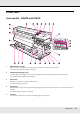
Printer Parts Front section - S50670 and S70670 1 Maintenance cover (left) Open this cover to clean the area around the print head. Normally closed when using the printer. See “Cleaning Around the Print Head” on page 126. 2 Additional print drying system The additional print drying system can be used to rapidly dry ink after printing. Available separately for the S70670. See the Additional Print Drying System Setup Guide. 3 After heater The heater can be used to rapidly dry ink after printing.
6 Roll core holder locking screw The locking screws keep the roll core holders in place once they have been attached to the roll core. There are two lift levers: one on the left and one on the right. 7 Roll support Place the used roll core for media take-up on these holders. There are two supports: one on the left and one on the right. 8 Auto switch Use this switch to select the auto take-up direction. Choose Off to disable auto take-up.
21 USB port Connects the USB cable. 22 Maintenance cover (right) Open this cover when performing regular maintenance. Normally closed when using the printer. See “Regular Maintenance” on page 121. 23 Media loading lever After loading media, lower the media loading lever to keep the media in place. Raise the lever to release the media prior to removal. 24 Alert lamp This lamp lights or flashes when an error occurs.
Front section - S30670 1 Maintenance cover (left) Open this cover to clean the area around the print head. Normally closed when using the printer. See “Cleaning Around the Print Head” on page 126. 2 After heater The heater can be used to rapidly dry ink after printing. See “Heating & Drying” on page 97. 3 Roll core holder Place the used roll core for media take-up on these holders. There are two holders: one on the left and one on the right. See“Media Loading and Take Up” on page 82.
8 Manual switch Use this switch to select the manual take-up direction. The selected option takes effect when the Auto switch is in the Off position. 9 Casters There are two casters on each leg. Once installation is complete, the front casters should be kept locked while the printer is in use. 10 Airflow vents These vents vent air from inside the printer. Do not obstruct these vents. 11 Waste ink bottle (tank) holder Place the waste ink bottle in this holder.
On/flashing : An error has occurred; the type of error is indicated by how the lamp lights or flashes. Check the message on the control panel’s screen. Off : No error. 24 Control panel See “Control panel” on page 20. 25 Front cover Open when loading media, cleaning the inside of the printer, or removing jammed media. Normally closed when using the printer. Inside - S70670, S50670 Dirt on any of the following parts may reduce print quality.
4 Pressure rollers (high) There are ten rollers in total; the high pressure rollers are the two on the outside edges. They press down on the edges of the media during ink layering. See “Cleaning the Platen Heater, Pressure Rollers, and Media Holding Plates” on page 112. See “High Print Quality” on page 27. 5 Pressure rollers (low) There are ten rollers in total; all of which are low pressure rollers apart from the two on the outside edges. They press down on the media during normal (non-layer) printing.
Inside - S30670 Dirt on any of the following parts may reduce print quality. Regularly clean or exchange these parts as described in the chapters listed in the reference sections below. 1 Print head The print head prints by moving left and right while emitting ink. We recommend that you clean the area around this unit once a week. Make sure the print head is at the far left side of the printer before cleaning. See “Cleaning Around the Print Head” on page 126.
7 Caps Except during printing, these caps cover the print head nozzles to prevent them from drying out. We recommend that the caps be cleaned once a week. See “Regular Part Cleaning” on page 124. 8 Wiper The wiper removes ink from the print head nozzles. We recommend that this unit be cleaned once a week. It is included in the maintenance kit and needs to be replaced about once every six months (or more often, depending on usage).
5 Pre-heater Heats the media before printing so that the print area is not subject to sudden changes in temperature. 6 Roll support Rest media on these supports before placing it on the roll holders. There are two supports: one on the left and one on the right. 7 Handle After placing media on the right roll holder, rotate the handle to press the holder and apply pressure to the roll core. LAN port 1 RJ-45 connector Connects the LAN cable. Use a shielded twisted pair cable (category 5 or higher).
Control panel 1 P button (power button) Turns the power on and off. 2 P light (power light) The printer's operational status is indicated by a lit or flashing light. On : The power is on. Flashing : The printer is receiving data or performing head cleaning or other operations during shut-down. Off : The power is off.
4 Display Displays the printer's status, menus, error messages, and so on. See “Understanding the Display” on page 22. 5 Menu button Press this button to display menus. See “Using the Control Panel Menu” on page 147. 6 y button (back button) Press this button to exit to the previous menu when options are displayed. See “Menu Operations” on page 147.
12 W button (pause/cancel button) The printer enters pause status if this is pressed while printing. To release the pause status, press the W button again, or select Pause Cancel on the screen and then press the Z button. To cancel print jobs being processed, select Job Cancel on the screen and then press the Z button. Pressing this button when menus are displayed closes the menus and returns the printer to ready status.
3 Media info From left to right, this display shows the selected media, platen gap, media width, and media remaining. If a media setting bank number created with this printer is selected as the print media, the number (from 1 to 30) will be displayed. When RIP Settings is selected, 0 will be displayed. The selected platen gap is shown as follows. : 1.5 : 2.0 : 2.5 The media remaining is not displayed if Off is selected for Remaining Setup in the Media Remaining menu.
Note: You can also check the level of ink remaining using the Ink Level option in the menus. See “The Ink Level Menu” on page 160. 2 Ink color codes BK : Black Y : Yellow M : Magenta C : Cyan MS Metallic Silver LK Light Black OR Orange LC Light Cyan LM Light Magenta WH White 5 Waste ink bottle status Displays the approximate amount of space available in the waste ink bottle. The display changes as shown below when the waste ink bottle is nearly full or an error occurs .
6 Head strike detection status This is displayed by the S50670 only. : The printer checks whether the media lifts during printing. : The printer does not check whether the media lifts during printing. See the “The Maintenance Menu” on page 159. 7 Additional print drying system status (system included with the S50670 and optional for other models) This display shows settings for the optional additional print drying system. No icon : Not installed, or it is not installed correctly.
Features This wide-format color ink jet printer supports roll media up to 1626 mm (64 inches) in width. The main features of this printer are described below. Realizing High Productivity Triple Heaters The three heaters listed below support improved productivity and print quality. The pre-heater: Warms media before printing to protect the print area from sudden changes in temperature. The platen heater: Ensures that the ink adheres evenly. The after heater: Can be used to rapidly dry ink after printing.
Additional Print Drying System Available The additional print drying system (included with the S50670; optional with other models) can be used for increased drying performance and improved productivity. It is recommended when using the S70670 in 10 color mode, as the white and metallic silver inks are slow to dry.
In addition to roll supports that give you a place to rest media during installation, the printer offers lift levers that allow heavy media to be effortlessly raised to the level of the roll holders. Virtually Odorless Solvent Ink The distinctive odor of solvent-based inks has been reduced with our solvent inks. This not only improves the work environment during printing but ensures that items intended for indoor display can be exhibited in any venue.
Notes on Usage and Storage Installation space Make sure that you secure the following space, clear of any other objects, so that paper ejection and consumable replacement are not obstructed. For the external dimensions of the printer, see “Specifications Table” on page 180. 100 mm (3.9 in.) 1750 mm (68.9 in.) 500 mm (19.7 in.) 1000 mm (39.4 in.) 3620 mm (142.5 in.) mm 00 in.) 10 9.4 (3 2903 mm (114.3 in.) 500 mm (19.7 in.
❏ Do not bend or tug the waste ink tube. Ink could spill inside or around the printer. ❏ The following components require regular maintenance at recommended intervals or according to the frequency with which the printer is used. Failure to perform regular maintenance could result in loss of print quality. In the absence of the appropriate maintenance, continued use could damage the print head. See “Regular Maintenance” on page 121.
Notes when not using the printer If you are not using it, note the following points when storing the printer. If it is not stored correctly, you may not be able to print properly the next time it is used. Additional precautions are required for white and metallic silver inks. See “Specialty Inks” on page 35. ❏ The pressure rollers may crease media left in the printer. The media may also become wavy or curled, causing jams or resulting in the media coming into contact with the print head.
Whether head washing is required depends on the length of time the printer will be left unused. ❏ S70670 (8 color mode): 2 weeks or more ❏ S50670 (4 color mode): 3 weeks or more ❏ S30670: 1 month or more See the “The Maintenance Menu” on page 159 for more information. Notes on handling ink cartridges Note the following points when handling ink cartridges to maintain good print quality. Additional precautions are required for white and metallic silver inks. See “Specialty Inks” on page 35.
❏ Use a cleaning stick from the supplied maintenance kit to wipe ink from the ink supply port of cartridges that have been removed from the printer before all the ink is used. Dried ink on the supply port may cause ink leaks when the cartridge is reinserted and used. While cartridges are in storage, keep the ink supply ports free of dust. The ink supply port has a valve in it so it does not need to be capped.
Notes on Handling ❏ Do not fold the media or damage the printable surface. ❏ Do not touch the printable surface. Moisture and oils from your hands can affect print quality. ❏ When handling media, hold it by both edges. We recommend wearing cotton gloves. ❏ Keep the media dry. ❏ Packaging materials can be used to store media and should not be thrown away. ❏ Avoid locations that are subject to direct sunlight, excessive heat, or humidity.
Specialty Inks The term “specialty inks” is used for white and metallic silver inks. White and metallic silver inks are prone to settling (components settling to the bottom of the liquid). Using the ink in this state can cause a decline in print quality and printer malfunction. This section describes precautions for handling white and metallic silver inks. The S30670 does not support specialty inks.
❏ If print results are uneven, circulate or refresh the ink. See “Maintenance Procedures for Specialty Inks” on page 117. Using the Supplied Software Contents of the Software CD The following applications are available on the supplied software CD. Install as required. For information about these applications, see the on-line help for the application in question. Note: ❏ The supplied disk does not contain printer drivers. A software RIP is required for printing.
2. Click the desired item in the EPSON LFP Remote Panel 2 main window. See EPSON LFP Remote Panel 2 help for more information. Exiting EPSON LFP Remote Panel 2 Click Finish in the EPSON LFP Remote Panel 2 main window. Uninstalling Software Important: ❏ Log in to an “Computer administrator” account (an account with Administrators group privileges). ❏ Enter the administrator password when prompted and then proceed with the remainder of the operation. ❏ Exit any other applications that may be running.
4. Select the target printer icon, and then click OK. 5. Follow the on-screen instructions to continue. When the delete confirmation message appears, click Yes. If you are reinstalling the EPSON communications driver, restart the computer.
Chapter 2 Basic Operations Loading and Exchanging Media The process for loading media varies with the model of printer or type of media feeding unit used. Choose the method suited to your particular setup. c Caution: ❏ The heaters and media holding plates may be hot; observe all necessary precautions. Failure to observe the necessary precautions could result in burns. ❏ Be careful not to trap your hands or fingers when opening or closing the front cover.
When the Standard Media Feeding Unit Is Installed This section uses the S70670 to illustrate the process of loading media when the supplied media feeding unit is installed. c Caution: Because the media is heavy, it should not be carried by one person. When loading or removing the media, use at least two persons. 1. Turn on the printer by pressing the P button.
Printable side out Printable side in Note: Be sure the option selected for Roll Type in the Customize Settings menu matches how the media is rolled. Roll Type defaults to Printable Side Out. Be sure to select Printable Side In after loading media rolled printable side in. For more information see “Roll Type” on page 98. 4. Place the left edge of the media in any of the black squares on the bar in back of the printer and the right edge on any of the holes on the back of the printer.
Note: If the label with black squares is not in place, affix the label as described in the Setup Guide. 5. Raise the lift lever on the left side of the printer to lift the media into position, then firmly insert the roll holder. If the roll of media has an outer diameter which is less than 140mm (5.5 inches), lift it up by your hands, and set it to the roll holder. The roll core will not reach the holder when raised using the lift lever. 6. Tighten the roll holder screw to fix the roll holder in place.
If the roll of media has the outer diameter which is less than 140mm (5.5 inches), lift it up by your hands, and set it to the roll holder as described in Step 5. 8. Tighten the roll holder screw to fix the roll holder in place.
9. Rotate the handle until part A in the illustration below is fully inserted. Important: Once part A is hidden, do not turn the handle any further. Failure to observe this precaution could damage the roll holder. 10. Raise the media loading lever.
11. Pull out the media and insert it into the printer. Note: Media that is heavy and difficult to unroll can be fed by pressing the drive switch on the left roll holder. Printable Side Out Printable Side In 12. Insert the media past the pressure rollers and lower the media loading lever to hold it in place. 13. Go to the front of the printer and open the front cover.
14. Hold the center of the media and raise the media loading lever. 15. Pull the media straight forward until the edge is past the label on the left side of the after heater. Keep the right edge of the media parallel with the scale markings on the two labels on the right side of the after heater. Important: Perform Steps 14 to 3 in reverse order and repeat the loading process if the right edge of the media is not within the scale markings.
Position the low pressure rollers 5 mm (0.20 inch) and the high pressure rollers 10 mm (0.39 inch) from the edges of the media, keeping them in the bounds shown by the black labels (see “Printable area - S70670/S50670” on page 107, “Printable Area S30670” on page 110, and “High Print Quality” on page 27). 17. Move unused rollers and rollers that can not be positioned over the media to the sides of the black labels. 18. Lower the media loading lever to hold the media in place.
Note: If you would prefer to print from the very start of the roll, press the u button in the control panel to rewind the media slightly. Be sure, however, to stop rewinding before the leading edge of the media is over the cutter groove (on the pressure roller side). 19. Attach the media holding plates at either side of the media. First, position the plates so that the edges of the media are in the centers of the round holes.
Important: ❏ Do not use the media holding plates with media that is more than 0.4 mm (0.02 inch) thick. The media holding plates could touch and damage the print head. ❏ Move the media holding plates to the left and right edges of the platen when they are not in use. ❏ Do not use the media holding plates if the sides of the printed media are smudged or torn. ❏ Leave left and right margins of over 10 mm (0.39 inch) when using the media holding plates.
Important: When white and metallic silver inks are installed, maintenance will be performed automatically to prevent ink accumulating in the printer and causing clogs. Because turning the printer off prevents maintenance being performed, leading to printer malfunction, we recommend that the printer not be turned off. 2. Loosen the roll holder fixing screws and adjust the roll holders so that the gap between the two is wider than the media.
Printable side in Note: Be sure the option selected for Roll Type in the Customize Settings menu matches how the media is rolled. Roll Type defaults to Printable Side Out. Be sure to select Printable Side In after loading media rolled printable side in. For more information, see “Roll Type” on page 98. 4. Place the left edge of the media in any of the black squares on the bar in back of the printer and the right edge on any of the holes on the back of the printer.
5. Align the media and the roll holders. Raise or lower the lifter until the media roll core is level with the roll holders. 6. Fully insert the left roll holder. Next, tighten the roll holder screw to fix the roll holder in place. 7. Fully insert the right roll holder. Next, tighten the roll holder screw to fix the roll holder in place.
8. Remove the lifter. 9. Rotate the handle until part A in the illustration below is fully inserted. Important: Once part A is hidden, do not turn the handle any further. Failure to observe this precaution could damage the roll holder. If part A is not hidden even after turning the handle until it can no longer be turned, return to step 7 and fully press the right unit into the roll core. 10. Raise the media loading lever.
11. Pull out the media and insert it into the printer. Note: Media that is heavy and difficult to unroll can be fed by pressing the drive switch on the left roll holder. Printable Side Out Printable Side In 12. Insert the media past the pressure rollers and lower the media loading lever to hold it in place. 13. Go to the front of the printer and open the front cover.
14. Hold the center of the media and raise the media loading lever. 15. Pull the media straight forward until the edge has past the label on the left side of the after heater. Keep the right edge of the media parallel with the scale markings on the two labels on the right side of the after heater. Important: Perform Steps 14 to 3 in reverse order and repeat the loading process if the right edge of the media is not within the scale markings.
Position the low pressure rollers 5 mm (0.20 inch) and the high pressure rollers 10 mm (0.39 inch) from the edges of the media, keeping them in the bounds shown by the black labels (see “Printable area - S70670/S50670” on page 107, “Printable Area S30670” on page 110, and “High Print Quality” on page 27). 17. Move unused rollers and rollers that can not be positioned over the media to the sides of the black labels. 18. Lower the media loading lever to hold the media in place.
Note: If you would prefer to print from the very start of the roll, press the u button in the control panel to rewind the media slightly. Be sure, however, to stop rewinding before the leading edge of the media is over the cutter groove (on the pressure roller side). 19. Attach the media holding plates at either side of the media. First, position the plates so that the edges of the media are in the centers of the round holes.
Important: ❏ Do not use the media holding plates with media that is more than 0.4 mm (0.02 inch) thick. The media holding plates could touch and damage the print head. ❏ Move the media holding plates to the left and right edges of the platen when they are not in use. ❏ Do not use the media holding plates if the sides of the printed media are smudged or torn. ❏ Leave left and right margins of over 10 mm (0.39 inch) when using the media holding plates.
Center the roll supports between the roll holders. Important: If the right holder handle shaft is not visible, rotate the holder forward until it stops. The media can not be properly loaded if the handle shaft is not visible. 3. Place media on the roll support oriented according to how it is rolled (see below) and position it as indicated by the mark on the label.
Printable side in If the label does not have the loading position, mark it on the label as instructed in the Setup Guide. Note: Be sure the option selected for Roll Type in the Customize Settings menu matches how the media is rolled. Roll Type defaults to Printable Side Out. Be sure to select Printable Side In after loading media rolled printable side in. For more information see “Roll Type” on page 98. 4.
If the roll of media has an outer diameter which is less than 140 mm (5.5 inches), lift it up by your hands, and place it on the roll holder. The roll core will not reach the holder when raised using the lift lever. 5. Tighten the roll holder screw to fix the roll holder in place. 6. Raise the lift lever on the right side of the printer to lift the media into position, then firmly insert the roll holder.
If the roll of media has an outer diameter which is less than 140 mm (5.5 inches), lift it up by your hands, and place it on the roll holder as described in Step 4. 7. Tighten the roll holder screw to fix the roll holder in place.
8. Rotate the handle until part A in the illustration below is fully inserted. Important: Once part A is hidden, do not turn the handle any further. Failure to observe this precaution could damage the roll holder. 9. Raise the media loading lever.
10. Pull out the media and insert it into the printer. Note: Media that is heavy and difficult to unroll can be fed by pressing the drive switch on the left roll holder. Printable side out Printable side in 11. Insert the media past the pressure rollers and lower the media loading lever to hold it in place. Confirm that the left edge of the media passes over the center of the square in the label on the pre-heater.
Important: Perform Steps 11 to 3 in reverse order and repeat the loading process if the left edge of the media is not within the guides. Do not attempt to reposition the roll holders while they are inserted in the media. 12. Go to the front of the printer and open the front cover. 13. Hold the center of the media and raise the media loading lever. 14. Pull the media straight forward until the edge is past the label on the left side of the after heater.
Keep the right edge of the media parallel to the scale markings on the two labels on the right side of the after heater. 15. Lower the media loading lever to hold the media in place. To print immediately, proceed to Step 16. For information on loading the media into the auto take-up reel unit, see “Using the Auto Take-up Reel Unit” on page 82. Note: If you would prefer to print from the very start of the roll, press the u button in the control panel to rewind the media slightly.
First, position the plates so that the edges of the media are in the centers of the round holes. Next, adjust the position so that the white line is visible in the square window and push the plates down to lock them in place and keep them from lifting. Important: ❏ Do not use the media holding plates with media that is more than 0.4 mm (0.02 inch) thick. The media holding plates could touch and damage the print head.
17. Close the front cover. Using the Optional Heavy Roll Media Feeding Unit This section describes how to load media when the optional heavy roll media feeding unit is installed. We recommend using a lifter for media over 40 kg (88.2 lb). The explanation that follows assumes that a lifter is used. The following types of lifter can be used. ❏ Fork or platform thickness: 28 mm (1.10 inches) or less ❏ Fork or platform can be lowered to approx.190 mm (7.5 inches) from the floor.
1. Turn on the printer by pressing the P button. 2. Loosen the roll holder fixing screws and adjust the roll holders so that the gap between the two is wider than the media. Important: If the right holder handle shaft is not visible, rotate the holder forward until it stops. The media can not be properly loaded if the handle shaft is not visible. 3. Place the media on a lifter oriented according to how it is rolled (see below) and move the lift to position the media as indicated by the mark on the label.
Printable side in If the label does not have the loading position, mark it on the label as instructed in the Setup Guide supplied with the optional heavy roll media system. Note: Be sure the option selected for Roll Type in the Customize Settings menu matches how the media is rolled. Roll Type defaults to Printable Side Out. Be sure to select Printable Side In after loading media rolled printable side in. For more information see “Roll Type” on page 98. 4. Align the media and the roll holders.
Raise or lower the lifter until the media roll core is level with the roll holders. 5. Fully insert the left roll holder. Next, tighten the roll holder screw to fix the roll holder in place. 6. Fully insert the right roll holder. Next, tighten the roll holder screw to fix the roll holder in place. 7. Remove the lifter.
8. Rotate the handle until part A in the illustration below is fully inserted. Important: Once part A is hidden, do not turn the handle any further. Failure to observe this precaution could damage the roll holder. If part A is not hidden even after turning the handle until it can no longer be turned, return to step 6 and fully press the right unit into the roll core. 9. Raise the media loading lever.
10. Pull out the media and insert it into the printer. Note: Media that is heavy and difficult to unroll can be fed by pressing the drive switch on the left roll holder. Printable side out Printable side in 11. Insert the media past the pressure rollers and lower the media loading lever to hold it in place. Confirm that the left edge of the media passes over the center of the square in the label on the pre-heater.
Important: Perform Steps 11 to 3 in reverse order and repeat the loading process if the left edge of the media is not within the guides. Do not attempt to reposition the roll holders while they are inserted in the media. 12. Go to the front of the printer and open the front cover. 13. Hold the center of the media and raise the media loading lever. 14. Pull the media straight forward until the edge has past the label on the left side of the after heater.
Keep the right edge of the media parallel with the scale markings on the two labels on the right side of the after heater. 15. Lower the media loading lever to hold the media in place. To print immediately, proceed to Step 16. For information on loading the media into the auto take-up reel unit, see “Using the Auto Take-up Reel Unit” on page 82. Note: If you would prefer to print from the very start of the roll, press the u button in the control panel to rewind the media slightly.
First, position the plates so that the edges of the media are in the centers of the round holes. Next, adjust the position until the white line is visible in the square window and push the plates down to lock them in place and keep them from lifting. Important: ❏ Do not use the media holding plates with media that is more than 0.4 mm (0.02 inch) thick. The media holding plates could touch and damage the print head.
17. Close the front cover. Viewing and Changing Media Settings The control panel displays the following information once the media lever is lowered. This display can be used to view or change the following two options: ❏ Remaining Setup On: The printer displays the amount of media remaining. Off: The printer does not display the amount of media remaining.
XXXXXXXXXXXXXXXXXX: Media settings are based on those stored in the printer in media settings bank No. 1. Media settings banks can store a variety of settings for different media based on the options selected in the Heater Temperature, Media Suction, Head Alignment, and other menus. Up to 30 combinations of settings can be stored by assigning them to banks No. 1 to 30.
The printer will display Ready after a brief pause, showing that it is ready to print. Transmit the data to be printed from the computer. Exchanging Media To replace the media after printing, print the amount of media remaining, cut the media, and remove the roll. Printing the Amount of Media Remaining The printer displays the amount of media remaining and any media low warnings in the control panel. This makes it possible to determine whether the media requires replacement before printing.
2. Press the M button, select Media Remaining in the menu, and press the Z button. 3. Select Print Remaining Length and press the Z button. 4. Press the Z button to print the amount of media remaining. Cutting Media Use a cutter (not included) to cut the media when printing is complete. This section described how to use a cutter to cut the media. c Caution: The heaters and media holding plate may be hot; observe all necessary precautions.
If you have printed the amount of media remaining, press the u button to rewind the media so that this information will remain on the roll after the media is cut. 3. Remove the media holding plates. 4. Cut the media with the cutter. Pass the blade of the cutter down the cutting groove.
Note: If you are using the auto take-up reel unit, set the Auto switch on the auto take-up reel unit to Off before using the Manual switch to position the media over the cutting groove. If you are using the S70670 or S50670 and do not intend to make additional prints, raise the media loading lever to prevent deformation of the pressure rollers. Removing Media You can now remove the media from the roll holders. To remove the media, reverse the steps you followed to load it.
c Caution: Be sure that your hands or hair do not get caught in the auto take-up reel unit while it is in operation. Failure to observe this precaution could result in injury. Follow the instructions in the manual when loading media or roll cores or removing media from the take-up roll. Dropping media, roll cores, or take-up rolls could result in injury.
Center the roll supports between the roll holders. 3. Align the right roll core holder with the right edge of the media and tighten the fixing screw. 4. Insert the roll core onto the right holder. 5. Insert the left holder into the roll core.
Slide the holder in until part A in the illustration below is fully inserted. Important: Stop when part A is no longer visible. The take-up reel unit may not function as expected if the holder is inserted too far. 6. Tighten the roll core holder fixing screw to fix the roll core holder in place. See the following for further instructions. For information on counterclockwise take up, see the following section. For information on clockwise take up, see “Clockwise Take Up” on page 88.
Counterclockwise Take Up 1. Attach the media to the take up roll core. Tape the media to the take up roll core in the center and then at the left and right edges. 2. Press the d button in the control panel to feed enough media for a single wrap around the roll core. 3. Flip the Auto switch to Off and press the Manual switch to around the roll core.
4. Flip the Auto switch to . 5. Lower the tension bar. 6. Press the d button to feed the media until the take up roll core begins to turn. Important: The auto take-up reel unit will not work if the tension bar is raised.
Clockwise Take Up 1. Attach the media to the take up roll core. Tape the media to the take up roll core in the center and then at the left and right edges. 2. Press the d button in the control panel to feed enough media for a single wrap around the roll core. 3. Flip the Auto switch to Off and press the Manual switch to around the roll core.
4. Flip the Auto switch to . 5. Lower the tension bar. 6. Press the d button to feed the media until the take up roll core begins to turn. Important: The auto take-up reel unit will not work if the tension bar is raised.
Removing the Take-up Roll The procedure for removing media varies depending on whether you are using the installed auto take-up reel unit or the optional auto take-up reel unit for heavy media. Follow the steps below when using the supplied auto take-up reel unit. c Caution: Because the media is heavy, it should not be carried by one person. When loading or removing the media, use at least two persons.
6. Loosen the right roll core holder fixing screw and remove the roll core holder from the roll. 7. Lower the roll onto the roll support. Before Printing To maintain print quality, perform the following inspection before starting work each day. ❏ Check the amount of ink remaining. If ink is expended during printing, printing can be resumed once the affected cartridge has been replaced.
White and metallic silver inks must be removed and shaken once every 24 hours. Although a message is displayed in the control panel 24 hours after the inks were last removed, we recommend that they be removed and shaken before the start of work. See “How to replace” on page 143. ❏ Print check pattern. Print a check pattern to check for clogged nozzles. Perform head cleaning if parts of the pattern are faint or missing. See “Checking for clogged nozzles” on page 114. See “Head Cleaning” on page 119.
❏ Head Movement ❏ Multi-Strike Printing ❏ Roll Type ❏ Tension Measurement ❏ Media Tension ❏ Feed Speed For more information on these items, see “The Media Setup Menu” on page 152. Saving Settings Follow the steps below to save media settings. Choosing a Media Setting Bank 1. After confirming that the printer is ready to print, press the Menu button. The settings menu will be displayed. 2. Select Media Setup and press the Z button. 3. Use the d/u buttons to select Customize Settings and press the Z button.
Note that any settings already saved to the printer will be overwritten. Setting Name Name the media setting bank. Using distinctive names makes it easier to select banks for use. 1. Select Setting Name and press the Z button. 2. Use the d/u buttons to display letters and symbols. When the desired character is displayed, press the r button to select the next entry position. Mistakes can be erased by pressing the l button to delete the previous character and move the cursor back one spot. 3.
Note: Feed Adjustment varies with the media used. Load the media for which feed adjustment is required under the same conditions as the actual print job. For example, if you are using the auto take-up reel unit for printing, the auto take-up reel unit should also be used for feed adjustment. Furthermore the media must be loaded and feed adjustment performed again after the heavy roll media system is installed even if feed adjustment has already been performed using standard roll media system.
Head Alignment Select Head Alignment to correct print head mis-alignment when print results seem grainy or out of focus. The Head Alignment menu contains two options: Auto and Manual. Auto head alignment aligns the head automatically using data collected by a sensor while a test pattern is printed. In manual adjustment, you need to check the pattern and enter the optimum adjustment value for alignment. This section details the steps involved in auto head alignment.
Heating & Drying Set the temperature of the heaters or turn the fan for the additional print drying system on or off (included with the S50670 and optional with other models). Note: Adjust heater temperature as follows: ❏ Set the heaters to the temperatures recommended in the documentation provided with the media, if available. ❏ Raise the temperature if the print results are blurred or smudged or the ink clots.
Head Movement Choose the range in which the print head moves during printing. 1. Use the d/u buttons to select Head Movement and press the Z button. 2. Use the d/u buttons to select the desired setting and press the Z button. For faster printing, select Data Width. For even, high-quality printing, select Printer Full Width. Multi-Strike Printing Choose the number of times each line is printed. 1. Use the d/u buttons to select Multi-Strike Printing and press the Z button. 2.
Media Tension Increase tension if creases appear in the media during printing. The higher the value, the greater the tension. If you have previously performed Feed Adjustment, you will need to perform it again after adjusting Media Tension. See “Feed Adjustment” on page 94. 1. Use the d/u buttons to select Media Tension and press the Z button. 2. Use the d/u buttons to choose a value. 3. Select the desired option and press the Z button. 4. Press the y button to return to the customize settings menu.
Platen heater: 40 °C (104 °F) After heater: 50 °C (122 °F) Heater status can be viewed in the control panel. See “Understanding the Display” on page 22. Additional Dryer defaults to On; at this setting, the fan turns on automatically when printing starts. Additional Dryer is available only when an additional print drying system is connected (system included with the S50670 and optional with other models). The following gives the procedure used when the optional additional print drying system is installed.
Additional Dryer (1) Use the d/u buttons to select On or Off. (2) Press the Z button. Correcting Print Misalignment (Head Alignment) Given that there is a slight gap between the print head and the media, the landing sites for the different colors of ink may be affected by humidity, temperature, inertial forces imparted by the print head, or the direction of the print head as it moves from right to left or left to right, or the use of two print heads (all models except S30670).
4. Use the d/u buttons to select a media setting bank number between 1 and 30 and then press the Z button. Note that any settings already saved in the printer will be overwritten. 5. Use the d/u buttons to select Head Alignment and press the Z button. 6. Use the d/u buttons to select Manual(Uni-D) or Manual(Bi-D) and press the Z button. 7. An alignment pattern will be printed. When printing is complete, the media will automatically be fed to a position where the pattern is clearly visible.
Feed Adjustment (Manual Feed Adjustment) Feed Adjustment is used to correct banding (horizontal banding, lines, or strips of uneven color). Feed Adjustment can be performed automatically or manually. For more information on automatic feed adjustment, see “Feed Adjustment” on page 94. This section explains how to perform manual feed adjustment. Two methods are available: ❏ Visually inspect print results and enter a correction by hand. ❏ Enter a correction during printing and inspect the results.
Using a Test Pattern Primary and Secondary adjustments are required. Normally the Secondary adjustment is performed after the Primary adjustment. Primary adjustment alone may be sufficient if you only wish to accurately print the length of a design. 1. After confirming that the printer is ready to print, press the Menu button. The settings menu will be displayed. 2. Select Media Setup and press the Z button. 3. Use the d/u buttons to select Customize Settings and press the Z button. 4.
When printing is complete, the media will automatically be fed to a position where the pattern is clearly visible. 10. Measure the distance between the “+” symbols. Record either the distance between the two center symbols or the average of the distances between the left, center, and right symbols. 11. Pattern length is displayed in the control panel. Using the d/u buttons, enter the value recorded in Step 10 and press the Z button. Note: To rewind the media, press the u button. Secondary Adjustment 12.
In the following example, this would be pattern number 3. 1 2 3 4 5 A 16. The pattern number is displayed in the control panel. Using the d/u buttons, enter the pattern number recorded in Step 15 and press the Z button. 17. Enter the number for each line, from A to F, and press the Z button. 18. The menus will close after you enter the pattern number for the last line. Note: To rewind the media, press the u button. Performing Feed Adjustment During Printing 1. Press the button during printing. 2.
If, in contrast, the feed amount is too large, white bands (pale stripes) will appear; adjust the feed amount downwards. 3. If you are not satisfied with the results, use the d/u buttons to enter an adjustment value. 4. Press the Z button when settings are complete. Once the feed amount has been adjusted, printing will continue at the new value. Note: The new value is erased when: ❏ The media loading lever is raised ❏ The printer is turned off ❏ Changes are made to Feed Adjustment in the Media Setup menu.
* Ink layering not available with media of this width. See “High Print Quality” on page 27. Note: Pressure rollers not within the bounds indicated by the black labels do not apply pressure to the media when the media loading lever is lowered. Pressure rollers that are within a black label but not over the media will cause friction during printing; be sure to position rollers that are not over the media outside the black labels.
508–1626 mm (20–64 in.) 10 mm (0.4 in.) 3–25 mm (0.1–1 in.)1 5 mm (0.2 in.) 10 mm (0.4 in.) 3–825 mm (0.1–32.5 in.)2 10 mm (0.4 in.) 10 mm (0.4 in.) 5 mm (0.2 in.) A: Pressure rollers (high) *1 The value selected for Side Margin(Left) in the setup menu. The default value is 5 mm (0.2 inch). *2 The total of the values selected for Print Start Position and Side Margin(Right) in the setup menu. The default value is 5 mm.
3–25 mm (0.1–1 in.)1 5 mm (0.2 in.) 300–1626 mm (11.8–64 in.) 5 mm (0.2 in.) 3–825 mm (0.1–32.5 in.)2 5 mm (0.2 in.) 5 mm (0.2 in.) A: Pressure rollers (low) *1 The value selected for Side Margin(Left) in the setup menu. The default value is 5 mm (0.2 inch). Choose a Side Margin(Left) over 10 mm (0.4 inch) when using media holding plates. *2 The total of the values selected for Print Start Position and Side Margin(Right) in the setup menu. The default value is 5 mm (0.2 inch).
1 (right edge of media) Varies with the option selected for Media Size Check. On selected for Media Size Check: The right edge of the media. Off selected for Media Size Check: The default right edge position (as far as the platen past the center of the label on the pre-heater). 2 (left edge of media) Varies with the option selected for Media Size Check. On selected for Media Size Check: The left edge of the media. Off selected for Media Size Check: 64 inches from the default right edge. 3–25 mm (0.1–1 in.
Chapter 3 Maintenance Daily Maintenance To maintain print quality, perform the following inspection and cleaning before starting work each day. Cleaning the Platen Heater, Pressure Rollers, and Media Holding Plates c Caution: ❏ The heaters and media holding plate may be hot; observe all necessary precautions. Failure to observe the necessary precautions could result in burns. ❏ Be careful not to trap your hands or fingers when opening or closing the front cover.
S70670, S50670: S30670: 5. Clean the media holding plates and platen heater.
Dampen a soft cloth in water, wring it out thoroughly, and use it to remove lint and dust from the media holding plates on both the left and right sides and from the platen. Checking for clogged nozzles We recommend that you check the nozzles for clogs each time you print to ensure quality results. Ways to Check for Clogs There are three ways to check for clogs.
Note: Auto Nozzle Check is not available under the following conditions: ❏ White ink is used in10 color mode (S70670) or 5 color mode (S50670). The check can still be performed with other colors. ❏ The media is transparent or colored. ❏ The printer is exposed to direct sunlight or interference from other ambient light sources. Shade the printer from sources of interference. ❏ 2.5 is selected for Platen Gap in the setup menu. Choose another option for Platen Gap.
This section explains how to print and inspect a check pattern. 1. After confirming that the printer is ready, press the # button. The Maintenance menu will be displayed. 2. Select Nozzle Check and press the Z button. 3. A nozzle pattern will be printed. When printing is complete, the media will automatically be fed to a position where the pattern is clearly visible. Cut the media if necessary. See “Cutting Media” on page 80. Note: To rewind the media, press u. 4. Inspect the nozzle pattern.
Example of clogged nozzles Perform head cleaning if any segments are missing from the pattern. See “Head Cleaning” on page 119. 5. The menus close when printing is complete. Head Mode Adjustment The S70670 and S50670 each have two print heads, meaning that if either clogs, printing can continue using the other. The head that will be used can be determined by printing a nozzle check pattern as part of a nozzle clog test. See “Checking for clogged nozzles” on page 114.
❏ Once every 24 hours, agitate the white and metallic silver ink cartridges. This prevents settling inside the cartridge. See “How to replace” on page 143. ❏ When white and metallic silver inks are installed, maintenance will be performed automatically to prevent ink accumulating in the printer and causing clogs. Because turning the printer off prevents maintenance being performed, leading to printer malfunction, we recommend that the printer not be turned off.
2. Using the d/u buttons, highlight Ink Circulation, WH,MS Ink Refresh, or WH,WH Ink Refresh and press Z. The printer will circulate or refresh the ink. Head Washing S70670 If the printer is to be stored for more than 1 week and powered off, it is recommended to perform a head washing on all colors. If the printer has been powered on, but has not printed for 2 weeks, it is recommended to perform a head washing on all colors.
Note: If colors are faint or missing even after head cleaning, perform regular part cleaning. See “Regular Part Cleaning” on page 124. Auto Maintenance Options The printer features handy auto maintenance options for performing regular head cleaning at an interval selected as described below. ❏ Periodical Cleaning Head cleaning is performed automatically at selected intervals of 1 to 240 hours. See “Printer Setup Menu” on page 156.
3. Choose the nozzles to be cleaned. All Nozzles Choose this option if all patterns in the printed nozzle check results contain faint or missing segments. If you select All Nozzles, proceed to Step 5. Selected Nozzles Choose this option if only some of the numbered patterns (nozzle arrays) in the printed nozzle check results contained faint or missing segments. You can select multiple nozzle arrays. 4. Choose the nozzle arrays to be cleaned.
Regular Part Cleaning: Preparation and Notes What You’ll Need Ready the following items before beginning regular part cleaning. ❏ Protective eyeware (not included) Protects your eyes from ink and ink cleaner. ❏ A maintenance kit (supplied with printer) Contains gloves, cleaning sticks, wiper, wiper cleaner, and flushing pad. Order new maintenance kits once the contents of the supplied maintenance kit are exhausted. See “Options and Consumable Products” on page 176.
Failure to observe this precaution could result in malfunction or reduced print quality. ❏ Use only the supplied cleaning sticks or sticks contained in maintenance kit (consumable kits, available separately). Other types of stick that produce lint will damage the print head. ❏ Always use fresh cleaning sticks. Re-using sticks can make stains even harder to remove. ❏ Do not touch the ends of the sticks. Oil from your hands could damage the print head.
1. Pour about 10 ml of ink cleaner into the cup supplied with the ink cleaner. 2. Dampen the cleaning stick with ink cleaner. Do not allow ink cleaner to drip from the cleaning stick. 3. Wipe the spot you wish to clean. Important: ❏ Ink cleaner should be used only to clean the area around the wiper, caps, and print head. Using ink cleaner on other parts of the printer could damage the product. ❏ Used ink cleaner is classified as industrial waste and should be disposed of in the same way as used ink.
Clean the parts in the following order: (1) Print head (2) Wiper (3) Caps (4) Wiper rail Moving the Print Head This section describes how to position the print head for part cleaning. Important: Be sure to follow the steps below when positioning the print head. Moving the print head manually could cause malfunction. 1. Confirm that the printer is on and press #. The Maintenance menu will be displayed. 2. Use the d/u buttons to select Head Maintenance and press the Z button. 3.
4. Open the maintenance covers at each end. Cleaning Around the Print Head Inspect the area around the print head and remove any ink stains as described below. Note that the S70670 and S50670 have two print heads; be sure to inspect both. 1. Use a cleaning stick to wipe the areas of the print head shown in the illustration. Important: Be sure to use a narrow cleaning stick to clean between the nozzles (the four colored areas shown in the illustration). Do not touch the nozzle surface.
S70670/S50670 The print head on the left is Head 1, and the print head on the right is Head 2.
Important: ❏ Be sure not to touch the nozzle surface during cleaning. Failure to observe this precaution could damage the print head. ❏ The parts shown below are sensors. Be careful not to touch this area with your hands or clean room wipes. Failure to observe this precaution could affect print quality. Cleaning Wiper and Caps The S70670 and S50670 have two wipers and ten caps. 1. Clean the front and back of the wiper with a cleaning stick.
2. Remove the wiper. Holding the wiper by the attachment point, tilt it to the left and lift it out. 3. Clean the front and back of the wiper with a cleaning stick. 4. Clean the bottom of the wiper with a cleaning stick.
5. Clean the attachment points with a cleaning stick. 6. Return the wiper when cleaning is complete. Place the wiper on the attachment point and press it down until it clicks into place. If the remaining wiper for the S70670 or S50670 is stained, repeat the process from Step 1. 7. Clean the edges of the wiper with a cleaning stick. The S70670 and S50670 have ten caps, the S30670 four.
Important: Do not touch the insides of the caps. Failure to observe this precaution could deform the affected parts. Cleaning the Wiper Rail Important: Failure to regularly clean the wiper rail could result in product malfunction. 1. Press the Z button to move the wiper to the rear. 2. Remove the wiper cleaner. Press the release lever as shown, then lift the wiper cleaner from the printer.
3. Dampen a cleaning stick with ink cleaner (available separately). See “Using Ink Cleaner” on page 123. 4. Clean the area shown. 5. Return the wiper cleaner that was removed in Step 2 to its original position. Place it on the attachment point and press down until you hear a click. Users of the S70670 or S50670 will need to return to Step 2 and clean the remaining rail. 6. Close both maintenance covers and press the Z button.
Disposing of Waste Ink When to Dispose of Waste Ink Be sure to replace the waste ink bottle when the following message is displayed in the control panel. ❏ Prepare empty waste ink bottle. ❏ Replace waste ink bottle and press Z. c Caution: ❏ Store waste ink in a location out of reach of children. ❏ Wear protective eyewear and gloves when replacing waste ink bottle.
Important: Only reset the counter when replacing the waste ink bottle. Resetting the counter before the waste ink bottle is replaced will result in the printer being unable to accurately track the waste ink level. Replacing the Waste Ink Bottle 1. Remove the waste ink bottle from the waste ink bottle holder. 2. Insert the waste ink tube into the mouth of the new waste ink bottle and place the waste ink bottle in the holder. Tightly seal the lid on the used waste ink bottle.
Important: ❏ Be sure to confirm that the waste ink tube is inserted in the mouth of the waste ink bottle. Ink will spill onto the surrounding area if the tube is not inserted in the bottle. ❏ You will need the lid for the waste ink bottle when disposing of waste ink. Keep the lid in a safe place; do not throw it out. 3. Press the Z button. 4. Check again to confirm that a fresh waste ink bottle is correctly placed and then press the Z button to reset the waste ink counter.
4. Open the right maintenance cover. 5. Remove the wiper cleaner. Grasp the cleaner as shown and lift it from the printer. 6. Insert a new wiper cleaner.
Place it on the attachment point and press down until you hear a click. 7. Remove the wiper. Holding the wiper by the attachment point, tilt it left and lift it out. 8. Insert the new wiper.
Place it on the attachment point and press down until you hear a click. Users of the S70670 or S50670 will need to return to Step 5 and replace the remaining wiper. 9. Close the maintenance cover and press the Z button. The menus will close when the print head returns to its normal position.
1. Confirm that the printer is on and press #. The Maintenance menu will be displayed. 2. Use the d/u buttons to select Head Maintenance and press the Z button. 3. Press the Z button to move the print head to the cleaning position. 4. Open the right maintenance cover. 5. Remove the flushing pad. Grasp the tab as shown below and lift the pad out of the printer. Immediately transfer the used flushing pad to a tray. Ink may leak from the pad. 6. Insert a new flushing pad.
Insert the two hooks on the flushing pad into the slots as shown and press the tab down until the pad clicks into place. 7. Close the maintenance cover and press the Z button. 8. The menus will close when the print head returns to its normal position.
Cleaning Check Sheet Print these pages to track maintenance tasks.
Regular Replacement Check Sheet Print these pages to track maintenance tasks. Component to be replaced Cleaned on date 1 Flushing pad / / / / / / / / / / / / / / / / / / / / / / / / / / / / / / / / / / / / / / / / / / / / / / / / / / / / / / / / / / / / / / / / / / / / / / / / / / / / / / / / 2 Wiper 3 Wiper cleaner 4 Waste ink bottle Explanation We recommend that this component be replaced once every six months.
Replacing Ink Cartridges If one of the installed ink cartridges is expended, printing cannot be performed. If an ink low warning is displayed, we recommend replacing the ink cartridge(s) as soon as possible. If an ink cartridge runs out while printing, you can continue printing after replacing the ink cartridge. However, when replacing ink during a print job, you may see a difference in color depending on the drying conditions.
3. Insert a finger into the depression on the top of the cartridge and pull the cartridge straight toward you. Important: Removed ink cartridges may have ink around the ink supply port, so be careful not to get any ink on the surrounding area when removing the cartridges. 4. Remove the new ink cartridge from its bag. Shake the ink cartridge horizontally about 5 cm (2-inch) to either side, making 50 passes over 15 seconds for the white, metallic silver, and orange inks.
Match the color of the cartridge to the color of the label on the printer. 6. Lower the lock lever to engage the lock. Repeat steps 2 to 6 to replace other ink cartridges. Important: ❏ Fill all slots using ink or replacement cartridges (replacement cartridges are required in 8 and 4 color modes). You cannot print if any of the slots are empty. ❏ White and metallic silver installed in the printer should be taken out and shaken as described in Step 4 once every 24 hours, other inks once every 3 weeks.
The message Print head is nearing end of service life. is displayed in the control panel as the time for replacement draws near. The printer can still be used while this message is displayed. Note: The message might not be displayed depending on your area. Print head life varies with operating conditions. Base the decision to replace the print head on the quality of the print results. Contact your dealer or EPSON Support for information on replacing components.
Chapter 4 Using the Control Panel Menu Menu Operations The menus are used as shown below. Menu List The following items and parameters can be set and executed in the Menu. See the reference pages for more details on each item. Items or values marked with a superscript “1” apply to the S70670 and S50670; items marked with a superscript “2” apply only to the S50670; items marked with a superscript “3” are not supported on the S70670.
Menu Item Media Setup Media Remaining See “The Media Setup Menu” on page 152. Parameter Remaining Setup On, Off Length 5.0 to 99.5 m (15 to 300 ft) Remaining Alert 1 to 15 m (4 to 50 ft) Print Remaining Length Print Select Media RIP Settings, 1 to 30 (media setting bank number) Customize Settings Current Settings Change settings for currently selected media. The options available depend on whether RIP Settings or a media setting bank is selected.
Menu Item Parameter Media Suction 0 to 10 Head Movement Data Width, Printer Full Width Multi-Strike Printing Off, 2 to 8 Roll Type Printable Side Out, Printable Side In Tension Measurement Periodically, Every page, Off Media Tension 0 to 40 Feed Speed 1 to 2 Print Media List Print Printer Setup Side Margin(Right) 3 to 25 mm (0.12 to 1.00 inch) See “Printer Setup Menu” on page 156. Side Margin(Left) 3 to 25 mm (0.12 to 1.00 inch) Print Start Position 0 to 800 mm (0.00 to 32.
Menu Item Parameter Maintenance Nozzle Check Print See “The Maintenance Menu” on page 159.
Menu Item Parameter Preference Date And Time MM/DD/YY HH:MM See “The Preference Menu” on page 162. Language Japanese, English, French, Italian, German, Portuguese, Spanish, Dutch, Russian, Korean, Chinese Unit: Length m, ft/in Unit: Temperature °C, F Alert Sound Setting On, Off Alert Lamp Setting On, Off Reset All Settings Yes, No See “The Reset All Settings Menu” on page 163.
Details of the Menu Items or values marked with a superscript “1” apply to the S70670 and S50670, while items marked with a superscript “2” are available with the S50670 only. Items marked with a superscript “3” are not supported on the S70670. The Media Setup Menu The Media Setup menu can be accessed directly by pressing the M button. indicates default settings.
Customize Settings Item Parameter Current Settings Explanation Change settings for currently selected media. The options available depend on whether RIP Settings or a media setting bank is selected. More information on the options available can be found below in the entries for RIP Settings and media setting banks 1 to 30. RIP Settings Item Parameter Explanation Platen Gap 1.5 Change Platen Gap (the gap between the print head and the media) for the media setting bank selected in the software RIP.
1 to 30 (media setting bank number) Item Parameter Setting Name Feed Adjustment Explanation Assign the media setting bank a name up to 22 half-size characters long. Using distinctive names makes it easier to select banks for use. Auto Manual Use this option if banding (horizontal banding, lines, or strips of uneven color) persists after head cleaning and head alignment have been performed.
Item Heater Temperature Parameter Explanation Pre-heater/platen heater: 30 °C to 50 °C (86 °F to 122 °F) The temperatures for the pre-, platen, and after heaters can each be adjusted separately. After heater: 30 °C to 55 °C (86 °F to 131 °F) Drying Time Per Pass 0 to 10sec Select the time the print head pauses to allow drying after each pass. Choose from values between 0.0 and 10.0 seconds. The time needed for the ink to dry varies with ink density and the media used.
Item Parameter Explanation Tension Measurement Periodically Choose Periodically or Every page to have the printer automatically monitor and adjust media tension during printing for optimal results, Off to disable automatic tension adjustment. Periodically is recommended in most circumstances. The printer may however be unable to adjust tension appropriately for some media, resulting in excessive slack or other maladjustments that cause printing problems, in which case you should select Off.
Item Parameter Explanation Media Size Check On Choose whether the printer automatically detects (On), or does not automatically detect (Off), the edges of the media. Try Off if the printer displays a Media Size Error when the media is correctly loaded. Note, however, that the printer may print beyond the edges of the media when Off is selected. Ink used outside the edges of the media will stain the inside of the printer. We generally recommend to operate with this setting set to On.
Item Nozzle Check Cycle Parameter Explanation Off Choose the frequency with which the printer performs an Auto Nozzle Check: never (Off) or once every 1 to 10 pages. Auto nozzle checks will not be performed while Off is selected. If 1 to 10 is selected, the printer will automatically checks for clogs at the specified interval by scanning a test pattern with a sensor as it is being printed. 1 to 10 pages Note that Auto Nozzle Check is not capable of detected all types of clog.
Item Parameter Explanation Heat Off Timer 15 to 240 minutes You can turn off the heaters automatically when no errors are detected and no print jobs are in progress. This option is used to choose the interval before the heaters turn off automatically. The printer will enter sleep mode when the Heat Off Timer expires. In sleep mode, the control panel turns off and the internal motors and other components consume less power.
Item Parameter WH,MS Ink Refresh1 Explanation Select this option should you notice uneven colors (areas of uneven density) once the printer is turned on following a period of disuse. WH,WH Ink Refresh1 WH,MS Ink Refresh is available when 10 color mode is selected for the S70670, WH,WH Ink Refresh when 5 color mode is selected for the S50670. See “Refresh” on page 118. Head Washing XX/XX The options displayed vary with the model of printer used.
The Print Logs Menu These items are used to track consumables. Item Parameter Explanation Print Job Log Sheet Print You can print the job information saved in the printer (up to 10 jobs). The information includes the media and ink used in each job, making it easier to track the use of consumables. Show Total Prints XXXXXX m2 (XXXXXX ft2) Select Show Total Prints to view the total area of media printed (to a maximum of six figures). The Printer Status Menu These items track printer use and settings.
Item Parameter Explanation Print Status Sheet Print Use Print Status Sheet to print the current network status. Use this information for a complete overview of network settings. Restore Settings Yes Select Yes to restore all items in the Network Setup menu to their default settings. No The Preference Menu indicates default settings. Item Parameter Explanation Date And Time MM/DD/YY HH:MM Set the printer’s built-in clock.
The Reset All Settings Menu Parameter Explanation Yes Select Yes to reset all settings in the Preference menu except Date And Time, Language, Unit: Length, and Unit: Temperature.
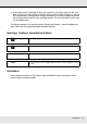
Chapter 5 Problem Solver When a Message is Displayed If one of the following messages is displayed, read and follow the instructions below. Messages What to do Prepare empty waste ink bottle. The waste ink bottle is getting full. Ready a new waste ink bottle. See “Options and Consumable Products” on page 176. Ink Cartridge Error Ink cartridge cannot be recognized. Insert again or replace ink cartridge. Remove and reinsert the ink cartridge.
Messages What to do Auto Take-up Reel Unit stopped. Media is not correctly attached to the auto take-up reel unit. Press the W button and select Job Cancel to cancel printing. Flip the Auto switch on the auto take-up reel unit to Off, then flip it back and reattach the media to the auto take-up reel unit. See “Media Loading and Take Up” on page 82. Media Size Error Load correct size media. The media currently loaded is not the correct width. Raise the media loading lever and remove the media.
When a Maintenance Call/Service Call Occurs Error messages What to do Maintenance Request Replace Part Soon/Replace Part Now XXXXXXXX A part used in the printer is nearing the end of its service life. Contact your dealer or EPSON Support and tell them the maintenance request code. You cannot clear the maintenance request until the part is replaced. A service call occurs if you continue to use the printer. Call For Service XXXX Error XXXX Power off and then on.
Troubleshooting You cannot print (because the printer does not work) The printer does not turn on. o Is the power cable plugged into the electrical outlet or the printer? Make sure the power cable is securely plugged into the printer. o Is there any problem with the electrical outlet? Make sure your outlet works by connecting the power cable for another electric product. The printer is not communicating with the computer.
o Connect the printer directly to the computer using a USB cable, and then try to print. If you can print via USB, there are some problems on the network environment. Ask your system administrator, or refer to the manual for your network system. If you cannot print via USB, see the appropriate section in this User’s Guide. The printer has an error. o Confirm if errors have occurred in the printer by checking the lights and messages on the printer's control panel.
The prints are not what you expected Print quality is poor, uneven, too light, or too dark. o Are the print head nozzles clogged? If the nozzles are clogged, specific nozzles do not fire ink and the print quality declines. Try printing a test pattern. See “Checking for clogged nozzles” on page 114. o Was Head Alignment performed? Select Head Alignment to realign the print head when print results seem grainy or out of focus. See “Correcting Print Misalignment (Head Alignment)” on page 101.
o Is Ink Low displayed on the control panel's screen? The print quality may decline when the ink is low. We recommend replacing the ink cartridge with a new one. If there is a difference in color after replacing the ink cartridge, try performing head cleaning a few times. The print is not positioned properly on the media. o Is the media loaded correctly and are the margins correct? If the media is not loaded correctly, the results may be off center or part of the data may not be printed.
o Is the print head scuffing the printed surface? Smear caused by the print head scuffing the media can be prevented by adjusting the Platen Gap to suit the media. It may also be prevented by choosing a high value for Media Tension. See “Platen Gap” on page 95 or “Media Tension” on page 99.
2. Continue pressing the tensioner until the projections on the inside at both ends contact the case. Media Jams o Is the media creased or folded? Media with a strong curl or that is folded back on its leading edge or creased may cause jams or other media feed problems. Do not use media affected by these types of problems. o Is the media too thick or too thin? Check the media specifications to determine whether it can be used in the printer.
Removing Jammed Media Follow the steps below to remove jammed media. c Caution: Be careful not to trap your hands or fingers when opening or closing the front cover. Failure to observe this precaution could result in injury. 1. Open the front cover. 2. Turn off the printer. If a message is displayed and the printer will not turn off, unplug both power cables. 3. Remove the media holding plates, if installed. Important: Cease use of the printer if the media holding plates are deformed.
4. If the print head is over the media, move it away from the jam. Important: Move the print head only after removing the media holding plates. Contact with deformed media holding plates could damage the print head. 5. Raise the media loading lever. 6. Pull the media to the cutter groove and use a cutter to remove torn or creased portions. 7. Manually rewind the cut media. 8. Remove any media that remains inside the printer. 9. Turn the printer on.
Important: If the printer is left off for an extended period, the print head will be left uncapped and dry out, and will not print properly when printing resumes. Turning the printer on automatically caps the print head. Reload the media and resume printing. See “Loading Media - S70670/S50670” on page 39 or “Loading Media - S30670” on page 58.
Chapter 6 Appendix Options and Consumable Products The following options and consumable products are available for use with your printer (as of February 2012). For the latest information, see the EPSON website. Product S70670 Ink cartridges S50670 Ink cartridges S30670 Ink cartridges Part number Explanation Black T715100 Cyan T715200 Magenta T715300 Yellow T715400 Epson recommends the use of genuine EPSON ink cartridges. Epson cannot guarantee the quality or reliability of non-genuine ink.
Product Part number Explanation Waste Ink Bottle T724000 Identical to the waste ink bottle supplied with the printer. Media Holding Plate C12C890891 Identical to the media holding plate supplied with the printer. High Speed Dryer C890751 Uses a fan to blow air over the media and assist drying (included with the S50670). See “The Media Setup Menu” on page 152. Heavy Roll Media System C12C890761 A media feeding unit and auto take-up reel for heavy rolls (up to 80 kg or 176.4 lb).
Moving and Transporting the Printer This section describes how to move and transport the product. Moving the Printer This section assumes that the product is being moved to another location on the same floor without traversing stairs, ramps, or lifts. See below for information on moving the printer between floors or to another building. See “Transport” on page 179. c Caution: Do not tilt the product more than 10 degrees forward or back while moving it.
6. Move the printer. Important: Use the casters on the dedicated printer stand to move the printer indoors a short distance over a level floor. They can not be used for transport. Post-Move Setup After moving the printer, follow the steps below to ready it for use. 1. Check that the new location is appropriate. See the Setup Guide. 2. Plug in the power cables and turn the printer on. See the Setup Guide. 3. Perform a nozzle check to check for clogged nozzles. See “Checking for clogged nozzles” on page 114.
Specifications Table Printer Specifications Printing method On-demand ink jet Nozzle configuration S70670: 360 nozzles × 2 rows × 10 colors (Metallic Silver, Light Black, Black, Cyan, Magenta, Yellow, Orange, Light Cyan, Light Magenta, White) S50670: 360 nozzles × 2 × 2 rows × 5 colors (White, Black, Cyan, Magenta, Yellow) S30670: 360 nozzles × 2 rows × 4 colors (black, cyan, magenta, yellow) Resolution (maximum) 1440 × 1440 dpi Control code ESC/P raster Media feed method Friction feed Built-in me
Printer Specifications Temperature Operating: 15 to 35 °C/59 to 95 °F (20 to 32 °C/68 to 90 °F recommended) Storage: -20 to 40°C (-4 to 104oF) (within a month at 40°C or 104oF) Humidity Operating: 20 to 80% (40 to 60% recommended) (without condensation) Storage: 5 to 85% (without condensation) Dimension Storage (minimum) dimensions: 2620 (W) × 963 (D) × 1311 (H) mm or 103.2 (W) × 37.9 (D) × 51.6 (H) inches Maximum dimensions: 2620 (W) × 1259 (D) × 1650 (H) mm or 103.2 (W) × 49.6 (D) × 65.
Standards and Approvals Safety UL 60950-1 CSA C22.2 No.60950-1 Low Voltage Directive 2006/95/EC EMC EN 60950-1 FCC part 15 subpart B Class A CAN/CSA-CEI/IEC CISPR 22 Class A AS/NZS CISPR 22 Class A EMC Directive 2004/108/EC EN 55022 Class A EN 55024 EN 61000-3-2 EN 61000-3-3 w Warning: This is a class A product. In a domestic environment this product may cause radio interference in which case the user may be required to take adequate measures.
WARNING The connection of a non-shielded equipment interface cable to this equipment will invalidate the FCC Certification of this device and may cause interference levels which exceed the limits established by the FCC for this equipment. It is the responsibility of the user to obtain and use a shielded equipment interface cable with this device. If this equipment has more than one interface connector, do not leave cables connected to unused interfaces.
Appendix A Where To Get Help New :See comments to select sections you need. The word "other" indicates products except for inkjet, SPC, Page, and SIDM. Contacting Epson Support Epson provides technical support and information on the installation, configuration, and operation of professional printing products through the EPSON Preferred Limited Warranty Plan. Dial (888) 377-6611, 6 AM to 6 PM, Pacific Time, Monday through Friday. Days and hours of support are subject to change without notice.
Chapter B Software License Terms Open Source Software Licenses Bonjour This printer product includes the open source software programs which apply the Apple Public Source License Version1.2 or its latest version ("Bonjour Programs"). We provide the source code of the Bonjour Programs pursuant to the Apple Public Source License Version1.2 or its latest version until five (5) years after the discontinuation of same model of this printer product.
1.3 "Covered Code" means the Original Code, Modifications, the combination of Original Code and any Modifications, and/or any respective portions thereof. 1.
(a) You must retain and reproduce in all copies of Original Code the copyright and other proprietary notices and disclaimers of Apple as they appear in the Original Code, and keep intact all notices in the Original Code that refer to this License; and (b) You must include a copy of this License with every copy of Source Code of Covered Code and documentation You distribute or Externally Deploy, and You may not offer or impose any terms on such Source Code that alter or restrict this License or the recipient
3. Your Grants.
8. NO WARRANTY OR SUPPORT. The Covered Code may contain in whole or in part pre-release, untested, or not fully tested works. The Covered Code may contain errors that could cause failures or loss of data, and may be incomplete or contain inaccuracies. You expressly acknowledge and agree that use of the Covered Code, or any portion thereof, is at Your sole and entire risk.
11. Ownership. Subject to the licenses granted under this License, each Contributor retains all rights, title and interest in and to any Modifications made by such Contributor. Apple retains all rights, title and interest in and to the Original Code and any Modifications made by or on behalf of Apple ("Apple Modifications"), and such Apple Modifications will not be automatically subject to this License.
13.3 Independent Development. Nothing in this License will impair Apple's right to acquire, license, develop, have others develop for it, market and/or distribute technology or products that perform the same or similar functions as, or otherwise compete with, Modifications, Larger Works, technology or products that You may develop, produce, market or distribute. 13.4 Waiver; Construction.
The Original Code and all software distributed under the License are distributed on an 'AS IS' basis, WITHOUT WARRANTY OF ANY KIND, EITHER EXPRESS OR IMPLIED, AND APPLE HEREBY DISCLAIMS ALL SUCH WARRANTIES, INCLUDING WITHOUT LIMITATION, ANY WARRANTIES OF MERCHANTABILITY, FITNESS FOR A PARTICULAR PURPOSE, QUIET ENJOYMENT OR NON-INFRINGEMENT. Please see the License for the specific language governing rights and limitations under the License.
3. Altered versions--including, but not limited to, ports to new operating systems, existing ports with new graphical interfaces, versions with modified or added functionality, and dynamic, shared, or static library versions not from Info-ZIP--must be plainly marked as such and must not be misrepresented as being the original source or, if binaries, compiled from the original source.