® ™ EPSON Expression 636 COLOR IMAGE SCANNER All rights reserved. No part of this publication may be reproduced, stored in a retrieval system, or transmitted in any form or by any means, electronic, mechanical, photocopying, recording, or otherwise, without the prior written permission of Seiko Epson Corporation. No patent liability is assumed with respect to the use of the information contained herein.
FCC Compliance Statement for United States Users This equipment has been tested and found to comply with the limits for a Class B digital device, pursuant to Part 15 of the FCC Rules. These limits are designed to provide reasonable protection against harmful interference in a residential installation. This equipment generates, uses, and can radiate radio frequency energy and, if not installed and used in accordance with the instructions, may cause harmful interference to radio or television reception.
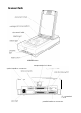
Scanner Parts OPERATE button transportation lock lever option interface connector And terminal parallel interface connector
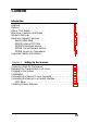
Contents lntroduction Features . . . . . . . . . . . . . . . . Options . . . . . . . . . . . . . . . . About This Guide . . . . . . . . . . Warnings, Cautions, and Notes . . Where to Get Help . . . . . . . . . Electronic Support Services . . . . World Wide Web . . . . . . . . EPSON Internet FTP Site . . . . EPSON Download Service . . . EPSON Fax-on-Demand Service EPSON Forum on CompuServe Important Safety Instructions . . .
Chapter 2 Scanner Basics Lights and Buttons . . . . . . . . . . . . . Scanner errors . . . . . . . . . . . . . . Placing a Document on the Scanner . . . Removing the Document Cover . . . . . Recommended Equipment . . . . . . . . RAM and hard disk size . . . . . . . . Accelerator boards . . . . . . . . . . . Video cards . . . . . . . . . . . . . . . Monitors . . . . . . . . . . . . . . . . . File compression software . . . . . . . Maintenance . . . . . . . . . . . . . . . . .
Chapter Troubleshooting Indicator Lights . . . . Command error . . Interface error . . . Fatal error . . . . . Option error . . . . Problems and Solutions . . . . . . . . . . . . . . . . . . . . . . . . . . . . . . . . . . . . . . . . . . . . . . . . . . . . . . . . . . . . . . . . . . . . . . . . . . . . . . . . . . . . . . . . . . . . . . . . . . . . . . . . . . . . . . . . . . . . . . . . . . . . . . . . . . . . . . . . . . 4-2 4-2 4-3 4-3 4-3 4-4 Appendix Scanner Specifications . . . . . . . .
The EPSON Expression™ 636 is a true 600-dpi full-color flatbed image scanner with a letter or A4 size scanning area. It has the ability to scan in color or grayscale, making it ideal for virtually all uses, from simple drawings to complex full-color illustrations. It provides extremely high-quality color scanning by reading 36 bits per pixel and saving 24 bits per pixel. Features The scanner offers the following features: 0 Full-color or grayscale reading.
0 Higher quality output with EPSON TWAIN’s “Best & de-screening” option. Selecting this option removes moire (interference) patterns from scanned images. 0 The EPSON Scan! II and EPSON TWAIN scanning utilities. This software lets you take full advantage of your scanner’s advanced features. You can scan images and save them to disk as files, use application programs that support the industry-standard TWAIN interface, export images in a variety of file formats, and calibrate your scanner.
About This Guide Chapter 1 describes setting up your scanner and connecting it to your computer. Be sure to read this first. Chapter 2 gives basic information on using your scanner, including maintenance and transportation. Chapter 3 describes how to use the optional transparency unit and automatic document feeder, and Chapter 4 provides troubleshooting information. The Appendix lists the scanner’s specifications. Warnings, Cautions, and Notes Warnings must be followed carefully to avoid bodily injury.
0 Technical information on installation, configuration, and operation of EPSON products 0 Customer relations. For answers to commonly asked questions about EPSON products 24 hours a day, 7 days a week, call EPSON Sound Advice at (800) 442-2110. You can purchase manuals, accessories, or parts from EPSON Accessories at (800) 873-7766 (U.S. sales only). In Canada, please call (800)873-7766 for dealer referral.
EPSON Download Service You can call the EPSON Download Service BBS at (800) 442-2007. Set your communications software to 8 data bits, 1 stop bit, no parity. Modem speed can be up to 28.8 Kbps. EPSON Fax-on-Demand Service You can access EPSON’s technical information library by calling (800) 442-2110 or (800) 922-8911 and selecting the appropriate phone option. You must provide a return fax number to use Fax-on-Demand.
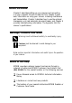
0 Use only the type of power source indicated on the scanner’s label. 0 Connect all equipment to properly grounded power outlets. Avoid using outlets on the same circuit as photocopiers or air control systems that regularly switch on and off. 0 Place the scanner near a wall outlet where the plug can be easily unplugged. Placez le scannezu pres d’une de contacte 024 la fiche peut2tre debranchke facilement. 0 Do not let the power cord become damaged or frayed.
Chapter 1 Setting Up the Scanner Choosing a Place for the Scanner . . . . . . . . . . . . . . . . . Releasing the Transportation Lock Lever Plugging in the Scanner 1-2 . . . . . . . . . . . . 1-3 . . . . . . . . . . . . . . . . . . . . . . 1-4 . . . . . . . . . . . . . . . . . . . . . . . . . . . . . 1-5 . . . . . . . . . . . 1-5 Connecting the Scanner to a Parallel Interface . . . . . . . . . . SCSI Setup . . . . . . . . . . . . . . . . . . . . . . . . . . . .
Choosing a Place for the Scanner Follow these guidelines when you select a location for the scanner: 0 Place the scanner on a flat, stable surface. The scanner does not operate properly if it is tilted or at an angle. 0 Place the scanner close enough to the computer for the interface cable to reach it easily. 0 Allow some space behind the scanner for the cables, and make sure to place the scanner where you can easily unplug the power cord.
Releasing the Transportation Lock Lever Before you connect the scanner to a power source, follow the steps below to release the transportation lock lever. 1. Place the scanner on a flat, stable surface with its rear panel facing you. 2. Slide the transportation lock lever to the UNLOCK position as shown below. Note: Be sure to return the transportation lock lever to the LOCK position before ~024 store OY transport the scanner.
Plugging in the Scanner 1. Connect the power cable to the power inlet on the back of the scanner and plug the other end into a properly grounded outlet as shown below. e 2. If any of the scanner’s lights come on, press the OPERATE button to turn off the scanner. e 1-4 Caution: There are several versions of this scanner designed for dzjJimxt voltages, and it is not possible to change the scanner’s voltage.
Initialization By observing the scanner’s initialization, you can make sure the scanner is operating properly before you connect it to your computer. 1. Open the document cover so you can see the operation of the scanner during initialization. 2. Turn on the scanner by pressing the OPERATE button. While the scanner is initializing, the fluorescent lamp on the carriage flashes. If the carriage is not at the home position (the rear of the scanner), it moves to the home position.
Note: IBM® PS/2® computers and some other PCs have built-in bidirectional parallel interfaces. You need to install an additional one in these computers only if you use the built-in parallel interface for your printer. Install a SCSI board in your computer, if necessary. Then connect the computer to the scanner’s SCSI connector as described under “SCSI Setup” on page 1-8.
2. Connect the 25-pin end of the cable to the computer; then tighten the screws on the sides of the connector. 3. Plug the 36-pin end of the cable into the scanner’s parallel interface connector. Then squeeze the wire clips together until they lock in place on both sides. Note: If your parallel cable has a ground wire, attack it to the scanner’s ground terminal.
SCSI Setup For some PCs, you must first install a SCSI board in your computer. All Macintosh computers have built-in SCSI ports; you do not need to install a SCSI board. Follow the directions below to connect the scanner to your PC or Macintosh. SCSI connections The SCSI interface allows you to connect up to eight devices, including the computer, in a “daisy chain” arrangement.
1. Locate the SCSI ID rotary switch on the rear panel of the scanner. 2. To change the scanner’s SCSI ID, turn the dial to the desired number. Caution: Do not set the scanner’s SCSI ID to a number that is already assigned to another device; the computer, scanner, and other devices will not function properly. Note: If your software supports only the ES-1200C scanner, set the dial to the position marked * to select ES-1200C Emulation mode. In ES-1200C Emulation mode, the scanner’s SCSI ID number is 2.
Using the termination switch The scanner has a built-in SCSI terminator. If the scanner is the only SCSI device you connect to your computer or if it is the last device in the daisy chain, leave the termination switch turned on. If the scanner is in the middle of a daisy chain, turn off the termination switch.
2. Connect the 50-pin end of the cable to either the top or bottom SCSI connector of the scanner; then squeeze the wire clips together until they lock in place on both sides. 3. Connect the other end of the cable to the SCSI port of your computer or other SCSI device. Note: The SCSI port of the Macintosh is the larger port with the SCSI icon @ over it. 4. Plug in the power cables of your computer, scanner, and other external SCSI devices. 5.
If you have an external hard disk, turn on the scanner, the external hard disk (which should be first in the daisy chain), and any other external SCSI devices you plan to use. Wait a few seconds; then turn on the computer. SCSI devices in the middle of the daisy chain may be left off if you don’t plan to use them. Installing Scanner Software Now that you have connected the scanner to your computer, the next thing to do is install your scanner software.
Chapter 2 Scanner Basics Lights and Buttons . . . . . . . . . . . . Scanner errors . . . . . . . . . . . . 2-2 2-3 Placing a Document on the Scanner . . 2-3 Removing the Document Cover . . . . 2-6 Recommended Equipment . . . . . . . RAM and hard disk size . . . . . . Accelerator boards . . . . . . . . . . Video cards . . . . . . . . . . . . . . Monitors . . . . . . . . . . . . . . . File compression software . . . . . 2-7 2-7 2-7 2-7 2-8 2-8 Maintenance . . . . . . . . . . . . . . .
Lights and Buttons The scanner has three indicator lights and two buttons. button button OPERATE light (green) Comes on when the scanner is turned on. READY light (green) Comes on when the scanner is ready to scan images. This light flashes during scanning. When an error occurs, this light and the ERROR light indicate the type of error. See the next page. ERROR light (red) Comes on when an error occurs. Along with the READY light, it indicates the type of error.
Scanner errors If an error occurs, the scanner stops operating and the READY and ERROR lights show the type of error. See Chapter 4, “Troubleshooting.” Placing a Document on the Scanner Before scanning a document: Remember to respect the rights of copyright owners. Do not scan published text or images without first checking the copyright status. 1. Turn on the scanner by pressing the OPERATE button. The OPERATE light comes on.
2-4 2. Turn on the computer and make sure that the scanner’s READY light is on. Open the document cover. 3. Place the document on the document table, with the side to be scanned down. Make sure that the document is carefully aligned.
4. Close the document cover gently so that the document does not move. Note: 5. 0 Make sure that the document is flat against the glass surface so that the image is properly focused. Also make sure to close the document cover. This prevents interference from external light. 0 Always keep the document table clean. See “Maintenance” later in this chapter for information on cleaning the scanner. 0 Avoid twisting the document cover when you open or close it.
Removing the Document Cover For thick documents or other materials that are hard to scan, you can remove the document cover. To do this, hold the back of the document cover behind the hinge and lift straight up. Do not force the cover off the scanner or lift from in front of the hinge. This may damage the cover. Note: When scanning with the cover removed, make sure you cover any exposed areas of the document table to prevent interference from external light.
Recommended Equipment Your scanner is sufficient for most scanning needs, but if you are not satisified with the quality of the images on your monitor or with the speed of image processing, read this section. While it does not contain specific recommendations, it describes various possibilities for improving your scanning system. For further information, see your dealer or an experienced scanner user.
The resolution of your monitor, of course, also affects the quality of the image you see. Consider a high resolution monitor if you do precise color work, but first be sure you have the right video card. File compression software Many different programs are available to make image files smaller for storage or transmission. For example, they can enable you to store a 3MB image file on a 1.44MB floppy disk.
Be careful not to scratch OY damage the glass of the d0c2md table, and a0 not use a hard OY abrasive brush to clean it. A damaged glass surface can decrease the scanning quality. 0 Never use alcohol, thinner, OY corrosive solvent to clean the scanner. These chemicals can damage the scanner components as well as the case. 0 Be careful not to spill liquid into the scanner mechanism OY electronic components. This could permanently damage the mechanism and circuitry.
Transporting the Scanner When you transport the scanner a long distance or store it for an extended period, follow the steps below to secure the carriage. 1. Turn on the scanner and wait until the carriage moves to the home position (the back of the scanner). Then turn off the scanner. 2. Slide the transportation lock lever to the LOCK position to secure the carriage. Note: If the scanner is broken, the carriage may not automatically return to the home position.
Chapter 3 Options Using the Transparency Unit . . . . . . . . . . . . Unpacking the transparency unit . . . . . . . . Removing the shipping screw . . . . . . . . . . Installing the transparency unit . . . . . . . . . Storing the transparency guides and reflective document mat . . . . . . . . . . . . . . . . . . Positioning transparencies and slides . . . . . Scanning normal (reflective) documents . . . . 3-2 3-2 3-3 3-4 Using the Automatic Document Feeder . . . . . . . . . . . . .
Using the Transparency Unit When installed on your scanner, the transparency unit provides high-quality, full-color scanning of transparencies and slides. Also, once you install the transparency unit, you can leave it in place when scanning normal reflective (paper) documents. Unpacking the transparency unit When you unpack your transparency unit, make sure you have all the items shown below and that none has been damaged during shipping. Contact your EPSON dealer if any item is missing or damaged.
Removing the shipping screw To prevent damage during shipping, a shipping screw is attached to the transparency unit. Follow the steps below to remove this screw before you install the transparency unit. 1. Turn the transparency unit so the glass side faces up. 2. Remove the screw as shown below. (labeled CLAMP 3. Insert the screw you just removed into the storage hole as shown.
Note: Before transporting the scanner, you need to remove the transparency unit and reattach its shipping screw. You can attach the shipping screw only when the transparency unit’s lamp assembly is in its home position. To move it to its home position when the transparency unit is attached to the scanner, close the transparency unit, turn on the scanner, and then turn it off. Installing the transparency unit Follow the steps below to install the transparency unit on the scanner.
3. Locate the two screws at the back of the scanner and slide the slots on the transparency unit forward underneath these two screws. 4. Insert the two screws provided with the transparency unit into the holes in the scanner as shown below, and then tighten the screws with a coin. 5. Close the transparency unit.
6. Connect the transparency unit’s cable to the option connector on the scanner. Then reconnect the scanner’s power cable. Storing the transparency guides and reflective document mat As shown on the next page, the transparency unit comes with three transparency guides for scanning transparencies or slides and a reflective document mat for scanning normal paper documents. To use the transparency guides, see “Positioning transparencies and slides” on the next page.
-ransparency guides I-L Positioning transparencies and slides You can scan transparencies or slides of various sizes using the transparency guides. Select the transparency guide to use according to the size of your transparency or slide as described in the table below. 1 Transparency or slide size 1 Appropriate transparency guide 1 Up to 2.4 x 3.5 inches (6 x 9 cm) 1 Small transparency guide Up to 4 x 5 inches (10.2 x 12.7 cm) Transparency guide with two 4 x5-inch openings Up to 4 x 10.25 inches (10.
If your transparency is larger than the sizes in the table above, you can place it directly on the scanner’s document table without using a transparency guide, as shown below. The transparency unit allows you to scan transparencies up to 8% x 11 inches (21.6 x 27.9 cm) in size. See your Scanning Utilities manual for information on scanning with the transparency unit.
2. Hold up the clear plastic flap and insert the transparency or slide in the transparency guide, as shown below. 3. Place the transparency guide containing the transparency or slide face down on the scanner’s document table, aligning it in the upper right corner as shown below. 4. If the reflective document mat is in place, remove it from the transparency unit. 5. Close the transparency unit. (If you do not close it completely, an option error results and you cannot scan the document.
Follow the steps below to position transparencies or slides using the transparency guide with two 10.25-inch-long openings: Open the transparency unit. Place the transparency guide on the scanner’s document table. Place the transparency face down on the document table, aligning it with the upper right corner of the transparency guide as shown below. 4. If the reflective document mat is in place, remove it from the transparency unit. 5. Close the transparency unit.
Scanning normal (reflective) documents To scan a normal reflective (paper) document when the transparency unit is installed, always use the reflective document mat included with the transparency unit. Also, make sure you remove the transparency guide from the scanner’s document table. Insert the reflective document mat as described below. 1. Open the transparency unit. 2. Insert the tabs on the reflective document mat into the slots on the transparency unit and slide the mat into place.
3. Position the reflective document and close the transparency unit. To remove the reflective document mat, slide it up and out of the slots on the transparency unit. Using the Automatic Document Feeder The automatic document feeder allows you to automatically load multiple-page documents into the scanner. It is particularly useful for OCR (optical character recognition) scanning, or for creating an image database.
Unpacking the automatic document feeder When you unpack your automatic document feeder, make sure you have all the items shown below and that none is damaged. If any item is missing or damaged, contact your EPSON dealer. two screws automatic document feeder Installing the automatic document feeder Follow the steps below to install the automatic document feeder on your scanner. Note: You cannot have the transparency unit and the automatic document feeder installed on the scanner at the same time. 1.
3. Locate the two screws at the back of the scanner and slide the slots on the automatic document feeder forward underneath these two screws. (Do not remove the protective materials from the automatic document feeder’s mounting hardware yet.) 4. Insert the two screws provided with the automatic document feeder into the holes in the scanner as shown below, and then tighten the screws with a coin.
5. Remove the protective materials from the automatic document feeder’s mounting hardware. 6. Close the automatic document feeder. 7. Connect the automatic document feeder’s cable to the option connector on the scanner. Then reconnect the scanner’s power cable. Loading documents in the automatic document feeder You can load up to 30 sheets in the automatic document feeder, based on a paper weight of 17 lb and a stack thickness of 0.24 inches (6.0 mm) or less.
Follow the steps below to load documents into the automatic document feeder. 1. Slide the left edge guide all the way to the left and place your documents in the feeder tray with the side you want to scan facing up. Then move the right edge guide so it is flush with the right edge of the document stack. Note: For checks, move the left edge guide to the center until it stops.
2. Insert the document stack into the automatic document feeder until it meets resistance. Documents are fed into the lower tray when scanning is finished. Paper jams If a paper jam occurs, first open the automatic document feeder’s cover. Then pull forward on the jam-release lever and slowly pull the jammed paper out of the feeder mechanism. (Be careful not to pull too hard; the paper may tear, making it more difficult to remove.
Loading documents manually You can load documents manually even when the automatic document feeder is installed. To load a document manually, lift the automatic document feeder and place the document on the scanning surface. Then lower the automatic document feeder and scan the document. Note: Always close the automatic document feeder and its cover before scanning. Opening the automatic document feeder or its cover while it is operating causes an option error, and paper feeding stops.
Document condition Check that your document is clean and in good condition before you load it in the automatic document feeder. Make sure of the following: 0 The ink on the document is dry. 0 The document has no holes or cut-out areas in it, and is not ripped or wrinkled. 0 The document has no staples, paper clips, or other materials attached to it. These may damage the feeder mechanism. 0 The document has no folds closer than 0.31 inches (8 mm) from its edges.
Chapter 4 Troubleshooting Indicator Lights . . Command error Interface error . Fatal error . . . Option error . . . . . . . . . . . . . . . . . . . . . . . . . . . . . . . . . . . . . 4-2 4-2 4-3 4-3 4-3 Problems and Solutions . . . . .
If you encounter any problems while using the scanner, check this chapter for possible solutions. Most problems fall into the following major categories: 0 Incorrect setup of the interface 0 Inappropriate selection of scanner functions 0 Incorrect setup of your computer or software 0 Incorrect operation of your software. Also see the documentation that came with your software, computer, and printer for possible solutions.
Interface error The interface setup is wrong, or the scanner is not properly connected to the computer. If this error occurs, check the interface connection. See “Connecting the Scanner to Your Computer” in Chapter 1. Then press the RESET button or turn the scanner off and back on to reset it. Fatal error This indicates one of the following problems: 0 The transportation lock lever is set to the LOCK position. 0 The fluorescent lamp needs to be replaced. 0 The scanner is broken.
Problems and Solutions The OPERATE light does not come on. Make sure the power cable is correctly plugged into the scanner and the power outlet. The READY light does not come on. Make sure the scanner is correctly connected to the computer and that the computer is turned on. The scanner does not start scanning. Make sure that you have selected the correct interface port and settings with your software. Also make sure the interface board in your computer is properly installed.
Make sure that your computer system meets the requirements, such as the operating system version, specified for your software. Confirm that the computer has enough memory for your software. If you are running other software at the same time, using RAM resident programs, or have many device drivers, the computer may not have enough memory left. (See your Easy Setup, application software, and computer manuals.) The entire image is distorted or blurred.
Color is patchy or distorted at the edges of the image. If the document is very thick or warped at the edges, the edges of the image may be discolored. Cover the edges of the document with opaque paper to block outside light. If part of the document extends beyond the document table, that edge may not be in contact with the document table. Change the position of the document. The image is faint or out of focus. Check that the document is placed flat against the document table.
Your software may not have sufficient color matching and color management features, or these components of your software may not be correctly installed. (See your application software and computer manuals.) If you are importing an image file into your application software, make sure the file format is one your software can read. Also check that the image settings in your application are appropriate for the type of image you want to scan. (See your application software and Scanning Utilities manuals.
Exact matching of colors is very difficult. Check your Scanning Utilities, application software, computer, and monitor manuals for information on color matching and calibration. Printed colors differ from those in the original document. Exact reproduction of colors is very difficult. See your application software manual for guidance on color matching. The printed image is larger or smaller than the original image. The image size settings in your software determine the size of the printed image.
Appendix . . . . . . . . . . . . . . . . . . . . . . . A-2 Electrical Specifications . . . . . . . . . . . . . . . . . . . . . . . A-3 Environmental Conditions . . . . . . . . . . . . . . . . . . . . . A-4 Safety Approvals . . . . . . . . . . . . . . . . . . . . . . . . . . . A-4 . . . . . . . . . . . . . . . . . A-5 Parallel Interface Specifications . . . . . . . . . . . . . . . . . . A-5 Scanner Specifications Source Document Specifications . . . . . . . . . . . . . . . . . . . . . . . . .
Scanner Specifications Scanner type: Flatbed, color Photoelectric device: Color CCD (Charged Coupled Device) line sensor Effective pixels: 5096 dots by 7020 dots at 600 dpi, 100% Document size: 8.5 x 11.7 inches (216 x 297 mm) letter or A4 size (The reading area can be specified from software.
Gamma correction: 2 types for CRT display 3 types for printer 1 type for user-defined Color correction: 1 type for CRT display 3 types for printer output (available in color line sequence mode only) 1 type for user-defined Interface: Bidirectional parallel and SCSI Light source: Xe-gas cold cathode fluorescent lamp Reliability: 100,000 cycles of carriage movements (main unit MCBF) Dimensions: Width: 13 inches (332 mm) Depth: 22.2 inches (563 mm) Height: 5.2 inches (133 mm) Weight: Approx.
Environmental Conditions Temperature: Operation 41” to 95” F (5’ to 35” C) Storage -13” to 140” F (-25” to 60” C) Humidity: Operation 10% to 80%, without condensation Storage 10% to 85%, without condensation Operating conditions: Ordinary office or home conditions. Extremely dusty conditions should be avoided. Operation under direct sunlight or near a strong light source should be avoided. Note: Specifications are subject to change without notice.
Source Document Specifications Reflective type: Opaque documents with smooth surfaces Transparency type: Reversal film, negative film (optional transparency unit required) Parallel Interface Specifications Interface type: Bidirectional parallel interface Data format: S-bit parallel Synchronization: By external strobe pulse Handshaking: By ACKNLG and BUSY signals Logic level: Input/output data and interface control signals are TTL compatible Connector type: 36-pin Centronics® type connector C
SCSI Specifications Interface type: ANSI X3.131-1986 standard Functions: BUS FREE phase ARBITRATION phase SELECTION/RESELECTION phase COMMAND phase (Logical unit number is fixed to 0 and command link function is not supported.) DATA phase Data in phase Data out phase STATUS phase MESSAGE phase MESSAGE IN phase MESSAGE OUT phase ATTENTION condition RESET condition Logic level: TTL compatible Electrical standard: ANSI X3.
Initialization The scanner can be initialized (returned to a fixed set of conditions) in the following ways: Hardware Software initialization initialization * The scanner is turned on. * The scanner receives an INIT signal from the parallel interface: pin 31 goes LOW. * The scanner receives a SCSI Reset signal from the SCSI interface. * Software sends the ESC @ (initialize the scanner) command.
lndex 24-bit color, 2-7 A A4, 1, 3-15, A-2 AAS, Intro-1 Accelerator board, 2-7 Automatic Area Segmentation (AAS), Intro-1 Automatic document feeder closing, 3-15, 3-17 cover, 3-13, 3-17 to 3-18 document condition, 3-19 document specifications, 3-18 edge guide, 3-16 feeder tray, 3-16 to 3-17 installing, 3-13 to 3-15 jam-release lever, 3-17 loading documents, 3-15 to 3-17 loading documents manually, 3-18 opening, 3-17 paper jams, 3-17 paper sizes, 3-15 precautions, 3-19 unpacking, 3-13 using, 3-12 to 3-17 B
Color 24-bit, 2-7 calibration, 4-8 correction, 4-7 distorted, 4-6 management, 4-7 matching, 4-7 to 4-8 millions of, 2-7 patchy, 4-6 printed, 4-8 true, 2-7 Command error, 4-2 Compression, file, 2-8 Connecting to Macintosh, 1-8 to 1-12 parallel interface, 1-6 to 1-7 PCS, 1-5 to 1-12 SCSI interface, 1-8 to 1-11 Connections, SCSI, 1-8 Connector, option, 3-6, 3-15 Contrast, 4-6 Copyright, 2-3 Cord, power, Intro-6, see also Cable, power Correction color, 4-7, A-3 gamma, 4-7, A-3 Cover, automatic document feeder,
Equipment, recommended, 2-7 to 2-8 Error command, 2-3, 4-2 fatal, 2-3, 4-3 interface, 2-3, 4-3 option, 2-3, 3-9, 3-10, 3-18, 4-3 scanner, 2-3 type, 4-2 to 4-3 ERROR light, 2-2, 2-3, 4-2 ES-1200C emulation, Intro-2, 1-9 Expansion board, 2-7 F Factory-set SCSI ID number, 1-9 Faint image, 4-6 Fatal error, 2-3, 4-3 Feeder tray, automatic document feeder, 3-16 to 3-17 File compression, 2-8 format, 4-7 Flashing, READY and ERROR lights, 2-9, 4-2 Fluorescent lamp, flashing in initialization, 1-5 replacing, 2-9, 4-
Interface error, 2-3, 4-3 parallel, 1-5 to 1-7, A-5 SCSI, 1-5 to 1-6, 1-8 to 1-11, 4-4, A-6 Interface cable, 1-5 to 1-8, 1-10 to 1-11 Interrupt setting, 4-4 J Jagged lines, 4-6 Jam-release lever, automatic document feeder, 3-17 Jammed paper, 3-17, 4-3 L Lamp assembly, transparency unit, 3-4 Lamp, fluorescent, 1-5, 2-9, 4-3 Letter, Intro-1, 3-15, A-2 Lever jam-release (automatic document feeder), 3-17 transportation lock, 1-3, 1-5, 2-10, 4-3 Light ERROR, 2-2, 2-3, 4-2 indicator, 2-2, 4-2 OPERATE, 2-2, 2-3,
Open automatic document feeder, 3-18 automatic document feeder cover, 3-17, 3-18 transparency unit, 3-8, 3-10, 3-13 OPERATE button, 1-4, 1-5, 2-2, 2-3 light, 2-2, 2-3, 4-4 Optical Character Recognition (OCR), Intro-1, Intro-2, 3-12 Option connector, 3-6, 3-15 error, 2-3, 3-9, 3-10, 3-18, 4-3 Options, 2, 3-1 to 3-18 Out of focus, 4-6 Output resolution, Intro-1, A-2 P Paper jam, 3-17, 4-3 Paper sizes, automatic document feeder, 3-15 Parallel interface, 1-5 to 1-7, A-5 Patchy color, 4-6 Placing document, 2-3
S Safety approvals, A-4 Safety instructions, Intro-5 to Intro-6 Scales, document table, 4-6 Scanner specifications, A-2 to A-6 Scanning, 2-3 to 2-5 Scanning normal documents (transparency unit), 3-11 to 3-12 Scanning reflective documents (transparency unit), 3-11 to 3-12 Screen, display, 4-6 Screw installing, 3-5, 3-13 to 3-14 shipping, 3-2 to 3-4 SCSI cable, 1-8, 1-10 to 1-11 connections, 1-8 ID number, 1-8 to 1-9, 4-4, A-6 ID rotary switch, 1-9 port, 1-6, 1-8, 1-11 power-on sequence, 1-11 to 1-12 specific
Transparency unit closing, 3-5, 3-9, 3-10 installing, 3-4 to 3-6 opening, 3-8, 3-10, 3-11 scanning normal documents, 3-11 to 3-12 scanning reflective documents, 3-11 to 3-12 unpacking, 3-2 using, 3-2 to 3-12 Transportation lock lever, 1-3, 1-5, 2-10, 4-3 Transporting scanner, 2-10 Troubleshooting, 4-2 to 4-8 True Color, 2-7 Turning on the scanner, 1-5, 1-11, 1-12 Unit, transparency, see Transparency unit UNLOCK position, 1-3, 1-5, 4-3 Unpacking automatic document feeder, 3-13 transparency unit, 3-2 V Vide