FCC COMPLIANCE STATEMENT FOR AMERICAN USERS This equipment generates and uses radio frequency energy and if not installed and used properly, that is, in strict accordance with the manufacturer’s instructions, may cause interference to radio and television reception.
Preface The User’s Manual for the FX Series printers consists of two volumes: Tutorial and Reference.
may use a version of BASIC other than Microsoft, you may need to modify some of the programs in this manual before they will run. Appendix F offers help, as do the next several paragraphs. Methods for sending BASIC print and listing commands to the screen and to the printer vary widely. We have used PRINT and LIST as the commands for the screen display, and LPRINT and LLIST as commands for the printer. You may have to change those to the form used by your system.
This format allows you to shorten a program line by combining a command and its print string. In the case of Double-Strike, for instance, the quoted letter “G” turns the mode on and “H” turns it off. To see how combining the code with a print string works, compare: 10 LPRINT CHR$(27)"G";"DOUBLE-STRIKE PRINT" with: 10 LPRINT CHR$(27)"GDOUBLE-STRIKE PRINT" The second program line may look peculiar, but it gives the same output that the first version does.
The computer ignores these remarks; they merely serve to help programmers understand at a glance the way a program is working. You may type them in or not, depending on whether you think you will want them in the future. We use the caret symbol (ˆ) to indicate exponents. For example: x = Yˆ2 means let X equal Y raised to the second power. Some computer systems use an up-arrow (t), which prints as a left bracket ([) on FX printers.
FX Series Printer User’s Manual Volume 1 Contents Preface . . . . . . . . . . . . . . . . . . . . . . . . . . . . . . . . . . . . . . Conventions Used in This Manual . . . . . . . . . . . . . . . . iii List of Figures ......................................................... Xiii List of Tables ....................................................... xvii Introduction . . . . . . . . . . . . . . . . . . . . . . . . . . . . . . . . . . . . . . . . . . . . . Inside the Printer . . . . . . . . . . . . . .
BASIC and the Printer . . . . . . . . . . . . . . . . . . . . . . . . . BASIC Communications . . . . . . . . . . . . . . . . . . . . . . . . Character strings . . . . . . . . . . . . . . . . . . . . . . . . . . . . BASIC print commands . . . . . . . . . . . . . . . . . . . . . . ASCII and BASIC basics . . . . . . . . . . . . . . . . . . . . . . Control codes . . . . . . . . . . . . . . . . . . . . . . . . . . . . . . . Escape-CHR$(27)-and other CHR$ commands Change Commands . . . . . . . . . . . . . . . . .
6 7 8 Special Printing Features . . . . . . . . . . . . . . . . . . . . . . . . Backspace . . . . . . . . . . . . . . . . . . . . . . . . . . . . . . . . . . . . Overstrikes . . . . . . . . . . . . . . . . . . . . . . . . . . . . . . . . . Offsets . . . . . . . . . . . . . . . . . . . . . . . . . . . . . . . . . . . . . Unidirectional Mode . . . . . . . . . . . . . . . . . . . . . . . . . . . International Characters . . . . . . . . . . . . . . . . . . . . . . . . Special Speeds . . . . . . . . . . . . .
Margins and Tabs . . . . . . . . . . . . . . . . . . . . . . . . . . . . . Margins.. . . . . . . . . . . . . . . . . . . . . . . . . . . . . . . . . . . . . Left margin . . . . . . . . . . . . . . . . . . . . . . . . . . . . . . . . . Margins and pitches . . . . . . . . . . . . . . . . . . . . . . . . . Right margin . . . . . . . . . . . . . . . . . . . . . . . . . . . . . . . Both margins . . . . . . . . . . . . . . . . . . . . . . . . . . . . . . . Tabs.. . . . . . . . . . . . . . . . . . . . . . . . . .
12 Design Your Own Graphics . . . . . . . . . . . . . . . . . . . . . Planning Process . . . . . . . . . . . . . . . . . . . . . . . . . . . . . . STRATA Program . . . . . . . . . . . . . . . . . . . . . . . . . . . . . Three-Dimensional Program . . . . . . . . . . . . . . . . . . . . First version of 3D program . . . . . . . . . . . . . . . . . . . Other versions . . . . . . . . . . . . . . . . . . . . . . . . . . . . . . Summary . . . . . . . . . . . . . . . . . . . . . . . . . . . . . . . . . . . .
16 17 xii Combining User-Defined Characters . . . . . . . . . . . . . . Large Letters: Double Wide . . . . . . . . . . . . . . . . . . . . . Large Letters: Double High . . . . . . . . . . . . . . . . . . . . . . Giant Letters: Double High and Double Wide . . . . . . Core Sets . . . . . . . . . . . . . . . . . . . . . . . . . . . . . . . . . . . . Line Graphics . . . . . . . . . . . . . . . . . . . . . . . . . . . . . . . . . Summary . . . . . . . . . . . . . . . . . . . . . . . . . . . . . . . . . . . .
List of Figures Easy-1 Easy-2 FX ticket program . . . . . . . . . . . . . . . . . . . . . . . . . . Ticket to success . . . . . . . . . . . . . . . . . . . . . . . . . . . 8 10 1-1 1-2 1-3 1-4 1-5 1-6 1-7 1-8 1-9 1-10 1-11 1-12 1-13 1-14 1-15 1-16 1-17 1-18 1-19 1-20 1-21 1-22 The FX-80 and FX-100 printers . . . . . . . . . . . . . . . Printer parts . . . . . . . . . . . . . . . . . . . . . . . . . . . . . . . Paperpath . . . . . . . . . . . . . . . . . . . . . . . . . . . . . . . . Paper separator . .
5-1 5-2 5-3 Master Select Program . . . . . . . . . . . . . . . . . . . . . . Master Select choices . . . . . . . . . . . . . . . . . . . . . . . Dress-up combinations . . . . . . . . . . . . . . . . . . . . . . 74 75 77 6-1 6-2 Bidirectional line . . . . . . . . . . . . . . . . . . . . . . . . . . . Unidirectional line . . . . . . . . . . . . . . . . . . . . . . . . . . 84 84 7-1 7-2 7-3 Default line spacing . . . . . . . . . . . . . . . . . . . . . . . . . Cascading STAIR STEPS . . . . . . . . . .
12-4 12-5 12-6 12-7 12-8 12-9 12-10 12-11 STRATA layout . . . . . . . . . . . . . . . . . . . . . . . . . . . STRATA logo . . . . . . . . . . . . . . . . . . . . . . . . . . . . . STRATA program . . . . . . . . . . . . . . . . . . . . . . . . . . Corner of the FX-80 design . . . . . . . . . . . . . . . . . . . FX-80 figure . . . . . . . . . . . . . . . . . . . . . . . . . . . . . . . Program for FX-80 figure . . . . . . . . . . . . . . . . . . . . FX-100 figure . . . . . . . . . . . . . . . . . . . . . . .
17-1 17-2 17-3 17-4 xvi Barchart . . . . . . . . . . . . . . . . . . . . . . . . . . . . . . . . . . Program for BARCHART . . . . . . . . . . . . . . . . . . . Statement form . . . . . . . . . . . . . . . . . . . . . . . . . . . . Program for STATEMENT . . . . . . . . . . . . . . . . . .
List of Tables 1-1 DIP switch functions ......................................... 23 2-1 2-2 2-3 Several computers’ print LIST commands ...... Several computers’ printer activating commands . ASCII codes on the FX ................................. 38 40 42 3-1 Summary of print pitches ................................. 60 4-1 Summary of modes ....................................... 67 5-1 5-2 Master Select Quick Reference Chart . . . . . . . . . . Print types . . . . . . . . . . . . . . . . . .
Introduction FX Features Epson’s MX series of printers attracted enough attention to become the most popular line of printers in the industry. Our FX printers follow in the same grand tradition. The FX printers’ power-packed assortment of features includes: l l Upward compatibility with most MX III features Several different print modes that can be combined to produce a variety of print styles.
l l Program debugging mode (hexadecimal dump of codes received from the computer) Fast print speed-160 characters per second-for rapid processing of documents l 2K print buffer for smooth operation l Adjustable tractor unit for narrow forms l Both friction- and tractor-feed capability l Replaceable print head l Easy-to-reach DIP switches to customize printer features.
You can use this manual as a reference, a tutorial study guide, or some combination of the two. l l l l l For those of you who want to use the printer for one simple application (like listing BASIC programs or using a word processing package), a description of the hardware and an overview of the software may be all that’s necessary. In this case, you need only Chapter 1, the Quick Reference Card at the back of Volume 2, and a knowledge of the program you are using.
Think of the manual as your personal guide in your exploration of the FX’s many features. For a preview of what your programs can produce, take a look at the following potpourri of print modes and graphics.
6
Programmer’s Easy Lesson Before you start, note that we haven’t claimed that one easy lesson will make you an FX maestro. It takes more than one lesson to learn the full value of the feature-packed FX printer. In fact, the more time you spend with this manual, the more your printer will cooperate with your every command. But some of you want to see something from a new printer right now-no matter what. The next few pages are especially for you.
feed the paper through. If you use single sheets of paper, the paperout sensor will cause a beep and stop the printing whenever the bottom edge passes the sensor. You can shut off the sensor by changing DIP switches as shown in Chapter 1. 3. Turn the printer and computer on and load a short BASIC pro- gram. Then send a listing to the printer (using LLIST, LIST “P“, or whatever your computer’s listing command is). You should get a single-spaced listing.
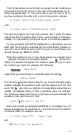
130 140 LPRINT "7 :"; E$" !X"; E$"4"; " " E$" - 1"; LPRINT "TICKET TO SUCCESS!"; E$"!@"; E$"5"; E$"+0"; 150 LPRINT H$": 9": FOR X=1 TO 2: LPRINT "7 :"H$ ":9": NEXT X 160 LPRINT "7 :";: LPRINT CHR$(14);E$;"E"; " 2"; 170 LPRINT CHR$(20);E$"F";E$"S1"; " SERIES"; E$“T”;H$; H$; 9” 180 LPRINT "4 :";: LPRINT CHR$(14);E$;"E"; " 1 3"; 190 LPRINT CHR$(20); E$"F"; E$"S1"; " PRINTERS"; E$ "T"; H$;": 5” 200 LPRINT "6 :"; H$;": 8": LPRINT "7 :";H$;": 9" 210 LPRINT "7 : " CHR$ (15) "BY" " E$"!X"; "EPSON AMERICA".
Figure Easy-2. Ticket to success Ticket Program Description This is not a complete explanation of the program. That’s what the rest of the manual is for. But this brief, line-by-line description should help those of you who wish to analyze the program. 10 Stores values in variables for easy access. E$ holds the ESCape code, CHR$(27). 20 Uses ESCape "1" to set the line spacing to 7/216-inch and the ESCape “D” sequence to set a horizontal tab stop at column 26.
110 Prints the outside border, then the top of the inside border (which was defined as the “:” character). 120 Prints another line of borders. 130 Prints more borders, then uses the Master Select to turn on Emphasized Double-Strike Pica. Also turns on Italic and Underline Modes. 140 Prints TICKET TO SUCCESS, then resets the FX to its defaults, including Pica, but does not affect the redefined characters. 150 Produces two more border lines.
280 Returns the printer to its defaults. 300-330 Provides data for the FX letters as user-defined characters 0-3. 350-410 Provides data for the ticket borders.
Chapter 1 The FX Printers Once you’ve unpacked your new printer, the first thing you should do is make sure you have all of the parts. With the FX-80 or FX-100 printer, you should receive the items shown in Figure 1-1: 1. The printer itself 2. A manual-feed knob 3. A paper separator 4. Two protective lids 5. One ribbon cartridge (in a box) 6. This FX Series Printer User’s Manual The FX-80 has a tractor built into its platen for handling continuousfeed paper between 9 ½ and 10 inches in width.
Figure 1-1.
Figure 1-2.
Additional Supplies and Accessories The following items may be purchased separately from your Epson dealer: Printer cable or interface kit. Each computer system has its own way of connecting to a printer. Some computers need a cable only, others require both a cable and board. The FX printers use the Centronics standard parallel interface scheme described in Appendix K.
Figure 1-3. Paper path Printer Preparation Once you’ve found a good home for FX, you’ll need to do some preparing before you can print. This section describes the first steps, which include installing a few parts, checking the setting of some internal switches, and then inserting the ribbon cartridge. Note: The printer should be turned OFF during all set-up operations.
Figure 1-4. Paper separator Covers For protection from dust and foreign objects and for quiet operation, FX printers use two types of covers. When you use the friction feed on either the FX-80 or the FX-100 or the built-in tractor on the FX-80, use the pair of flat protective lids (Figure 1-5). When you use the removable tractor unit, use the tractor cover (Figure 1-6). Install the center protective lid by inserting tabs into slots (one tab per side on the FX-80, two on the FX-100).
fitting over its post. Lower the cover. To remove the cover, move it to its full vertical position and then lift it up and a little to the left. Figure 1-5. Protective lids Figure 1-6. Tractor cover Manual-feed knob The manual-feed knob (Figure 1-7) can aid you in loading and adjusting paper.
the right side and twist until the flat sides of rod and fitting match. Push the knob straight in with a steady pressure. To remove, pull straight out. Figure 1-7. Manual-feed knob DIP switches Several tiny switches, called DIP (for Dual In-line Package) switches, are located inside the FX. They control a number of important printer functions, such as line-feed adjustment, the paper-out sensor, the beeper, and the default print modes.
Figure 1-8.
These switches are set at the factory, and most of them you will never need to touch. You may, however, want to take the time now to match up the switches with their functions, as shown in Table 1-1. For a further discussion of the DIP switches, see Appendix E. Figure 1-9. DIP switch location Figure 2-20. DIP switch factory settings Always turn the power off (with the switch on the left side of the printer) before touching any internal switch. The printer checks most switch settings only at power-up.
Table 1-1. DIP switch functions Switch 1 No. O N 1-8 ON 1-7 ON 1-6 ON 1-5 Emphasized Function International character International character International character Print weight 1-4 2K buffer RAM memory 1-3 Inactive 1-2 0 (slashed) 1-1 Compressed Paper-out sensor Zero character Print pitch OFF OFF OFF OFF Single strike User-defined characters Active 0 Pica Switch 2 No.
end of the cartridge into the corresponding slots in the printer frame (Figure 1-11). The cartridge should snap neatly into place. With the paper bail resting on the platen, you can tuck the ribbon between the metal ribbon guide and the black print head. As Figure 1-11 suggests, you can ease the ribbon into place with the deft application of a dull pencil. To remove any slack in the ribbon, turn the ribbon knob in the direction of the arrow.
Figure 1-11.
Figure 1-12. Printer readied for paper insertion l l l l Be sure the printer is turned off. Lift the front protective lid and move the print head to the middle of the platen. Remove the center protective lid. Pull the paper bail and the friction-control lever toward the front of the printer. Your printer should now look like Figure 1-12. Adjust the pin-feed levers to approximate the width of paper you are using.
Figure 1-13. Pin feeder adjustment very important to keep the paper straight so that the pins on both sides engage at the same time. If the paper does not move smoothly, remove it by reversing the manual-feed knob and start again with an unwrinkled sheet. Figure 1-14.
l As the paper comes up the front of the platen, watch to be sure that it is feeding under the black edges of the pin feeders. If your paper is wrinkling as it comes through, you may need to readjust the pin feeders. Reinstall the center protective lid underneath the paper. Push the paper bail back against the paper and close the front protective lid. You are now ready to set the top of form, as shown at the end of this section.
Now follow these steps to load your paper into the friction feeder: l l l Be sure the printer is turned off, Lift the front protective lid and move the print head to the middle of the platen (refer back to Figure 1-12). Pull the paper bail up. Engage the friction-control mechanism by pushing the frictioncontrol lever to the back. Guide the paper under the paper separator and the platen with your left hand, while turning the manual-feed knob with your right hand. If you hear a crinkling noise, stop.
sides of the tractor assembly are firmly in place. Rock the front of the unit downward, pressing firmly until it locks into place. Figure 1-16. Tractor unit installation Figure 1-17.
To load the paper into the unit, use this procedure: l l l l l Be sure the printer is turned off; then open the front protective lid to move the print head to the middle of the platen. Pull the paper bail and the friction-control lever toward the front of the printer (refer back to Figure 1-12). Insert the paper under the paper separator and the platen and push the paper through to the front. Position the pin feeders, using the pin-feed locking levers to make the adjustment.
Top-of-form position After you have loaded the paper, you should set it to the top of form, which is the position of the print head when you turn the printer on. (Since the computer term form corresponds to the word page, it may be easier for you to think of this as the top of the page.) To make this setting, advance the paper until a perforation lies slightly below the top of the ribbon.
Figure 1-19. Top of form 1-21). The other end of the cable plugs into your computer. If your cable includes grounding wires, be sure to fasten the wires to the grounding screws at each end. With the paper loaded, turn the printer on with the toggle switch at the left-rear comer of the FX. You get a little dance from the print head and three lights go on: the POWER light, the READY light, and the ON LINE light. If the ON LINE and READY lights are not on, push the button marked ON LINE.
Figure 1-20.
Figure 1-21. Cable connection Control panel When the control panel’s ON LINE light is on, the printer and computer are in direct communication and the FF (form feed) and LF (line feed) buttons have no effect. Go ahead, try pushing one. To use the FF and LF button; press the ON LINE button to turn it off. Now you can see what the other buttons do. Press the LF button briefly, then release it. That produces one line feed. Now hold the LF button down for a moment to produce several line feeds.
loaded because the printer’s test uses all 136 columns. Turn the printer completely off (with the switch on the left side of the printer), press down the LF button, and turn the printer back on again while still holding down the LF button. Figure 1-22. Sample automatic test Figure 1-22 shows the FX’s automatic test, which prints the standard characters that are stored in the printer. The test pattern continues until you turn the printer off.
Chapter 2 BASIC and the Printer While you read this manual, you’ll be testing your FX with programs in the BASIC language. You can, of course, use another language with your printer; see Appendixes A through D for the ASCII and ESCape codes that your software manual will explain how to use. Here we use BASIC because it is the most popular language for personal computers. One of the simplest things you can do with any FX printer is print listings of your BASIC programs.
Table 2-1. Several computers’ print LIST commands Command Computer LLIST Epson QX-10™, IBM-PC®, and Radio Shack TRS-80® LIST"COM0:" PR#1 Epson HX-20 Notebook Computer™ Apple® II LIST PR#0 If your listing is more than a page long (or if you didn’t start the listing at the top of a page), your printer may have printed right over the perforation. Set DIP switch 2-3 to the on position, and the printer will automatically skip over the perforation. We discuss this further in Chapter 8.
Character strings The character-string (or CHR$) function converts any decimal number from zero through 255 to a character or action. Its format is CHR$ followed by a number in parentheses, for example, CHR$(84). The character-string command follows a PRINT or LPRINT command and causes your computer system to send an ASCII code to the computer’s screen or to the printer. What gets printed or performed is determined by the particular modified ASCII table that is used by your system.
Table 2-2. Several computers’ printer activating commands Computer Activating commands 10 LPRINT CHR$(193) Epson QX-10, IBM-PC, and Radio Shack TRS-80 5 OPEN "0",#1, "COMØ" 10 PRINT#1, CHR$(193) 99 CLOSE#1 Epson HX-20 Notebook Computer 5 PR#1 Apple II 10 PRINT CHR$ (193) 99 PR#Ø Check your computer’s reference manual and type in the commands appropriate to your computer. Then type RUN.
instead of an Italic A, pay close attention to the next three paragraphs. The original ASCII code was designed to use the decimal numbers zero through 127. Computer systems designers soon decided to extend this range (to 0 through 255) in order to make room for more features. Unfortunately, some designers did not anticipate that printers would make use of this extended range.
Now RUN it. You should hear a short beep. (If you don’t hear it, check DIP switch 2-2, using the procedure we gave in Chapter 1.) That’s the printer’s beeper, which most often sounds to inform you that you’ve run out of paper (Appendix F lists other causes of beeping). When you produce the beep, you’ve proved that on your computer certain codes do indeed perform printer functions. Table 2-3 shows the ranges that the FX uses when it interprets ASCII codes for characters and functions. Table 2-3.
Here are two examples of ESCape code sequences: LPRINT CHR$(27)CHR$(71) LPRINT CHR$(27)CHR$(38)CHR$(0)CHR$(1)CHR$(3) To see how such sequences work, start a new program now by entering: 10 LPRINT CHR$(27)CHR$(52) 20 LPRINT "ITALIC CHARACTER SET" and RUNning it. When you can RUN a program, we show you the results that you should expect: ITALIC CHARACTER SET Note: If you haven’t yet read the Preface, which includes “Conventions Used in This Manual,” this is the time to do it.
Change Commands After you have sent commands to the printer, you will often want to change them, either to turn off one or more modes, or to erase text. To understand what happens when you use one of the several FX methods of making changes, you need to know about two special aspects of the printer, defaults and the printer buffer. We often talk in these pages about resetting the printer to its defaults. By defaults, we mean the settings that are in effect whenever you turn the printer on.
Reset Code You could turn off the Italic Mode by turning the printer off, then back on. Although turning the printer off resets the printer to its defaults, which include Roman Mode, cycling the printer off and on may disrupt computer/printer communications. FX printers have a Reset Code to avoid that: ESCape CHR$(64). To see the Reset Code work, add these lines to your budding program: 30 LPRINT CHR$(27)CHR$(64) 40 LPRINT "BACK TO ROMAN WITH THE RESET CODE" and RUN it.
ITALIC CHARACTER SET BACK 'TO ROMAN WITH ITALIC OFF Notice that CHR$(53) turned Italic off and the semicolon at the end of line 30 eliminated the blank line between the two lines of text. DELete and CANcel But suppose you don’t want that much power. Suppose you only want to erase text in the print buffer without affecting any print modes. Two codes do this: DELete and CANcel. DELete, which is CHR$(127), removes the latest text character from the buffer without affecting control codes.
of line 10 is the number 4, and the symbol for the 53 of line 30 is the number 5, so enter the following: 10 LPRINT CHR$(27)“4” 30 LPRINT CHR$(27)"5"; Now use RUN to make sure that both ESCape sequences work as before. You can also shorten your programs by storing the ESCape code in a character string. If you enter A$=CHR$(27) in an early line of a program, you can simply enter A$ each time you want the ESCape code.
See the Preface for a list of the conventions used in this manual, Appendix A for a table of the ASCII codes, and Appendixes B and C for tables of the control codes. Appendix F offers programming solutions to interfacing problems, while Appendix E lists the defaults and shows the DIP switch settings. See also the Quick Reference Card.
Chapter 3 Print Pitches ' One of the big advantages an FX printer has over a daisy-wheel printer or a typewriter is the ability it gives you to choose from a variety of widths, or pitches, for your characters. To use this feature well, it’s important to understand just how an FX prints. The technique used by an FX printer is called dot-matrix printing. Dot-Matrix Printing A dot matrix is a grid or graph that someone who designs a character set for a dot matrix printer uses.
Figure 3-1 shows one each of lower- and uppercase letters. The p gives an example of the way a few lowercase letters use the bottom two rows of the matrix. All numbers, uppercase letters, and most symbols are formed within the top seven rows of the matrix. Main columns The construction of the print head restricts the maximum height of any character to nine dots. As shown in Figure 3-2, the print head uses a vertical column of nine pins (actually, wires).
Intermediate positions FX characters are designed to be five or fewer columns wide. Leaving the sixth column blank allows for space between letters. Figure 3-3 shows the 6 main columns, numbered 1, 3, 5, etc. Figure 3-3. Main columns Because the use of 5 dots does not give quite enough detail for the highest quality characters, an FX prints some dots half way between the main columns in the 6-dot-wide matrix.
If you look through Appendix A, you’ll notice that none of the FX’s characters use dots in consecutive main and intermediate columns in the same row. There is a reason for this: the printer’s speed. The FX recalls a character’s dot-matrix pattern from ROM and prints it in 1/160th of a second. At that speed, the print head is simply moving too fast to pull the pins back and forth in time to print an overlapping dot. This fact is critical when you design characters, as you will see in Chapter 15.
Figure 3-5. Pica and Elite letters 3Ø LPRINT CHR$(27)"P"; 4Ø LPRINT WIDTH" PICA PITCH IS THE NORMAL PRINT When you RUN it, you should get: COMPARE ELITE PITCH WITH THE PICA BELOW PICA PITCH IS THE NORMAL PRINT WIDTH Figure 3-6. Pitch comparison The 10 blank spaces in line 20 above print as 10 Elite spaces; the 10 corresponding spaces in line 40 print as Pica spaces. This means, as you can see in Figure 3-6, that the different width modes affect spaces as well as characters.
NEW 2Ø LPRINT CHR$(15)"COMPRESSED MODE IS SET WITH CHR$(15)" 3Ø LPRINT "IT WILL STAY ON UNTIL YOU CANCEL IT" 4Ø LPRINT CHR$(l8)"PICA AGAIN" COMPRESSED MODE IS SET WITH CHR$(15) IT WILL STAY ON UNTIL YOU CANCEL IT PICA AGAIN Notice that we had you use only CHR$(l5) to turn Compressed Mode on-that is, we didn’t have you type in an ESCape code first. If you prefer consistency to brevity, you may add one and use ESCape CHR$(15) to get the same effect.
DIP switch 1-1 on. This adjustment will make the printer reset to Compressed Mode, after which you can switch to other modes as needed. You could get Pica Mode with control codes, for instance, by using the Compressed shut-off code: CHR$(18). Then you could return to Compressed with either of the usual commands-CHR$(15) or ESCape " @ “-or by turning the printer off and back on. Mode priorities These first three pitches-Pica (10 cpi), Elite (12 cpi), and Compressed (17.16 cpi)-are mutually exclusive.
Don’t take this lesson lightly-it is a good example of how print modes interact on FX printers. Pitch Mode Combinations The previous three modes can’t be mixed, but the next mode can be used in combination with any one of them. And you can add it to a printout for either of two durations, for one print line or for a longer passage. Expanded Mode Expanded Mode doubles the width of the current pitch mode.
40 LPRINT "CONTINUOUSLY WITH ESCAPE W" 50 LPRINT CHR$(27)"W"CHR$(0) The printer extends the dot matrix by spreading the dots horizontally to twice their normal distances apart, and then it adds a duplicate of each dot to the next main dot column (see Figure 3-7). Figure 3-7.
CHR$(1) can use an alternative form for this pair. For continuous Expanded, and for the other modes which use CHR$(1) and CHR$(0) as a toggle switch, you can use an abbreviation. Here, for example, you can use: LPRINT CHR$(27)"W"CHR$(1) or you can use: LPRINT CHR$(27)"W1" for the same result. Expanded Mode works equally well with any of the three basic pitches.
By deleting the semicolon at the end of line 10 and adding a semicolon to the end of line 30, you can mix all six print pitches on a single print line. In program lines 30 to 70, CHR$(14) and CHR$(20) move the printer in and out of Expanded Mode. This program turns Compressed Mode on in line 40, and Compressed stays on until the Reset Code turns it off in line 80. It gets replaced (masked) in line 60 when the program turns on Elite Mode, which has a higher priority.
Table 3-1.
Chapter 4 Print Quality In the last chapter you learned how to change the width of the printed characters to achieve six different print pitches. The FX printer also offers several modes that improve print quality without affecting pitch. The three new modes that we discuss in this chapter are Double-Strike, Emphasized, and Proportional. After we cover these modes separately, we discuss combining them with pitch modes.
The way Double-Strike gets this result is rather clever: the FX prints each character in the regular fashion until it reaches either the end of the line or the point at which you have Double-Strike turn off. Then the FX shifts the paper up slightly and prints the Double-Strike passage again. This means that every dot in each row of the character gets a shadow (see Figure 4-1). Double-Strike Mode fills in some of the more visible gaps between the dots of a character. The end result is better looking print.
DOUBLE-STRIKE PRINT IS DARKER THAN SINGLE-STRIKE EMPHASIZED ADDS A TOUCH OF CLASS That’s right, Emphasized is very similar to Expanded print, except that Expanded Mode prints a duplicate set of dots a full (rather than a half) column to the right of the initial set. Figure 4-2 shows Expanded and Emphasized characters. Figure 4-2. Expanded and Emphasized letters Although the print head slows to half normal speed (i.e., 80 cps) in Emphasized Mode, the increase in print quality is well worth it.
Emphasized Mode (line 30) stays on until you shut it off. DoubleStrike comes on (line 40) before Emphasized is turned off. You see the result above. Proportional Mode Have you ever wondered why most computer printouts don’t look as good as typeset books, even when you use bold characters? It’s because most dot-matrix printers use a uniform width for each character (monospacing) whereas typesetting machines set the width for each character proportional to its size.
Since all Proportional characters are Emphasized, it makes sense that Proportional characters, like Emphasized, can only be printed in Pica pitch, not Elite nor Compressed. In addition, Proportional Mode cannot be mixed with Double-Strike. The cost of all this high-powered printing is the slower speed of printing and the wear and tear on the ribbon. Understandably, these dense modes shorten the life of a ribbon compared to Single-Strike printing.
the printer will prove that Double-Strike has been turned on all the time.
sized, strips excess space from between characters. Double-Strike can be combined with all other modes except Proportional, whereas Emphasized, and thus Proportional, cannot be combined with either Elite or Compressed. Mode combinations are governed by the FX’s priority list. This list determines which mode gets printed when two or more conflicting modes are active at the same time. Table 4-1 shows the modes we have covered so far. Table 4-1.
68
Chapter 5 Dress-Up Modes and Master Select In the first three subsections of this chapter, we cover four more print modes: Underline; two Script Modes-Superscript and Subscript; and Italic. Each of these modes allows you to add a particular finishing touch to your printouts. After we show how you can quickly select 16 combinations of pitch and weight by using the Master Select feature, we demonstrate combining the combinations.
You can turn Underline Mode off with: CHR$(27)"-"CHR$(0) or CHR$(27)"-0" Enter and RUN this program to see what FX underlining looks like: NEW 20 LPRINT CHR$(27)"-1UNDERLINING IS SIMPLE"; 40 LPRINT CHR$(27)"-0 TO TURN ON/OFF" UNDERLINING IS SIMPLE TO TURN ON/OFF You can underline virtually anything you want-even a series of blank spaces.
The FX-80, on the other hand, can perform a reverse line feed, and it uses this capability to place the underline one row lower than any text dot. To do this, the FX-80 prints the text to be underlined, moves the print head down the paper one row’s worth to print the underline, then moves the print head back up to the original text line.
Notice that ESCape “T” turns either kind of Script Mode off and also that both versions of Script Mode are automatically printed in Double-Strike. Since Double-Strike prints at half speed, so do the Script Modes. And since Double-Strike can’t mix with Proportional, neither can either type of Script. If you are using the FX-100 and you switch in and out of DoubleStrike Mode several times in the same line, you will see that the print line slopes slightly to the right.
Whether your computer system is one of these or not, with ESCape “4” you can print Italic characters. Prove it by adding these lines to your program: 10 LPRINT CHR$(27)“4” 70 LPRINT CHR$(27)"@" When you want to turn off only the Italic Mode, you use ESCape "5" (instead of line 70’s Reset Code) in your program. More Mode Combinations With all the handsome print types we’ve covered up to this point, you’re probably wondering how many different print combinations are waiting in your FX.
NEW 20 Y$(1)="SINGLE-STRIKE Y$(2)="SNGL-STRIKE EMPHASIZED " 30 Y$(3)="DOUBLE-STRIKE Y$(4)="DBL-STRIKE EMPHASIZED " 40 Z$(1)="PICA Z$(2)="ELITE : Z$(3)="COMPRESSED 50, FOR X=1 TO 2 60 FOR Y=1 TO 4 70 FOR Z=1 TO 3 80 READ N: IF N<0 THEN 130 90 LPRINT CHR$(27)"!"CHR$(0);: IF N<10 THEN LPRINT " " ; 95 ' OK to substitute CHR$(2) for CHR$(0) l00 LPRINT N; CHR$(27)"!"CHR$(N); 110 LPRINT Y$(Y);: IF X=2 THEN LPRINT "EXPANDED "; 120 LPRINT Z$(Z) 130 NEXT Z: NEXT Y: NEXT X 140 LPRINT CHR$(27)"!"CHR$(0) 150 DATA 0,1,
0 SINGLE-STRIKE PICA 1 SINGLE-STRIKE ELITE 4 SINGLE-STRIKE COMPRESSED 8 SNGL-STRIKE EMPHASIZED PICA 16 DOUBLE-STRIKE PICA 17 DOUBLE-STRIKE ELITE 20 DOUBLE-STRIKE COMPRESSED 24 DEL-STRIKE EMPHASIZED PICA 3 2 S I N G L E - S T R I K E P I C A E X P A N D E D 3 3 S I N G L E - S T R I K E E X P A N D E D E L I T E 36 SINGLE-STRIKE EXPANDED COMPRESSED 4 0 S N G L -S T R I K E E M P H A S I Z E D E X P A N D E D 4 8 D O U B L E -S T R I K E E X P A N D E D P I C A 4 9 D O U B L E - S T R I K E E X P A N D E
Double-Strike, use LPRINT CHR$(27)“!T". N/A indicates that the two modes cannot be combined. Table 5-1.
Figure 5-3. Dress-up combinations Master Select base and then add the sequence(s) that you want to embellish it. Here is a program that does just that, several times.
Here are the commands that we introduced in this chapter. CHR$(27) “-1” Turns Underline Mode ON CHR$(27)“-0” Turns Underline OFF CHR$(27)“S1” Turns Subscript Mode ON.
80
Chapter 6 Special Printing Features In this chapter you’ll discover several new features that will enhance your control over the printer. Backspacing, for example, allows you to combine characters. You can use a set of software commands to switch in and out of international character sets, and you can control the speed of printing. Backspace The backspace function is handy for making overstrikes. Because it moves the print head backward one character, you can print two characters in one print position.
use the same technique to produce the plus-or-minus symbol: 10 LPRINT CHR$(27)"S0+"CHR$(8); 'Plus/minus 20 LPRINT CHR$(27)"S1-" 30 LPRINT CHR$(27)"@" ± How about that, and it only took three lines. Next try this approximately equally short program: 10 LPRINT CHR$(126)CHR$(8); ' Approximately equal 20 LPRINT CHR$(27)"J"CHR$(11)CHR$(126) 30 LPRINT CHR$(27)"@" This program prints CHR$(126), a diacritical mark used in Spanish that is called a tilde.
The 17 backspaces (line 40) are printed in Compressed Mode. The difference in character widths makes the second printing of the word BACKSPACES be offset from the first. In the next program, the offset is a little more dramatic. Change the following lines: 30 LPRINT "BACKSPACE"CHR$(15); 40 FOR X=1 TO 15: LPRINT CHR$(8);: NEXT X 50 LPRINT CHR$(18)"BACKSPACE" After the FX prints each BACKSPACE, it moves the print head 15 Compressed positions backward. Instead of bold characters, you get a shadow effect.
Figure 6-1. Bidirectional line Look carefully at your printout or at the version we show as Figure 6-1. See how the line seems to quiver? Now turn on Unidirectional printing to see how much difference it makes. Add line 10 and RUN the program again: 10 LPRINT CHR$(27)"U1" Figure 6-2. Unidirectional line CHR$(27) “U1" turns on the Unidirectional printing whose results we show as Figure 6-2, and CHR$(27)“U0” turns it off.
line feed, which means that the subsequent movement of the print head will be from the left margin to the right. To see this in action, delete line 10 and change line 40 to read: 40 FOR X=1 TO 10: LPRINT CHR$(27)"<"CHR$(124): NEXT X When you RUN it, you can watch the print head move to its leftmost position after it prints each line. Unidirectional print motion straightens out the slight misalignment of characters that results from printing bidirectionally in the Elite or Compressed Mode.
that are used in different countries. These international characters can be accessed with: LPRINT CHR$(27)"R"CHR$(n); where n is a number from zero to eight. The ESCape “R” sequence selects one of these nine countries: 0 1 2 USA 3 France 4 Germany 5 United Kingdom 6 Denmark 7 Sweden 8 Italy Spain Japan Once you have selected a country, you can use its special characters. Choosing a new international character set, however, does not give you a completely new set of 256 characters.
Table 6-2. International characters in Roman typeface USA FRANCE GERMANY U.K. DENMARK SWEDEN ITALY SPAIN JAPAN This program provides an easy reference to the international characters; you’ll probably want to keep the printout handy. You can also print international characters in Italic Mode. Change these two lines: 80 READ C$: LPRINT C$CHR$(137)CHR$(14)CHR$(27)"4"; 100 NEXT X: LPRINT CHR$(27)"5": NEXT Y to get the result shown in Table 6-3: Table 6-3.
When could you use this program? Well, you can print . . . and if you want to use one of the foreign sets all the time, you can change your printer’s default. The factory setting of a default international character set-for the USA-is shown in line 1 of Table 6-4. You can change this by resetting some of the FX’s DIP switches. Three switches: Switch 1-6 Switch 1-7 Switch 1-8 generate eight combinations. Table 6-4 shows the switch settings. Table 6-4.
either of these capabilites on and off, as a mode, with an ESCape sequence. Half-Speed Mode The FX can print at the fine rate of 160 characters per second (cps). But it will also print more slowly if you want it to: the Half-Speed Mode prints at 80 cps. The command sequence uses lowercase s plus zero and one as a toggle: LPRINT CHR$(27)"s1" turns Half Speed Mode on, and, as usual, the zero version of the command turns the mode off.
and print the contents of the buffer, press RETURN alone. Now add this line: 10 LPRINT CHR$(27)"i1" And RUN the program. Your FX-80 responds to your typing-immediately. When you are finished, press RETURN alone, then use the zero version of the command to return to full speed. Summary You can use the Backspace Mode to overstrike one or more characters. In this manner, you can combine two or more characters to form completely new ones.
CHR$(27)“s1” Turns Half-Speed ON; If your system can’t send lowercase letters, use CHR$(115) CHR$(1) CHR$(27)“s0” Turns Half-Speed OFF CHR$(27)“i1” For the FX-80 only, turns Immediate-Print Mode ON. If your system can’t send lowercase letters, use CHR$(105)CHR$(1).
92
Chapter 7 Line Spacing and Line Feeds Up to this point in the manual, we have not discussed the way the printer moves a page so that it doesn’t print lines of text right on top of each other. Now we do. In this chapter you will learn how to change the distance that the paper moves; the movement is called a line feed, and the distance is called a line space. The ability to change line spacing is vital to printing graphics, as you will see in later chapters.
Figure 7-1.
Your first STEPS print in 12-dot spacing. Now tighten up the line spacing by adding lines 10 and 50: 10 LPRINT CHR$(27)"0" 50 LPRINT CHR$(27)"2" The CHR$(27)“0” of line 10 changes the usual 12-dot (1/6-inch) line spacing to a handy variation: 9-dot (l/B-inch) spacing. Nine-dot spacing is especially useful in the 9-pin Graphics Mode that we introduce in Chapter 11. Another convenient line spacing is 7-dot (7/72-inch).
To show what varying n can mean, the following program increases the line spacing by one dot’s worth on each line feed: 20 FOR X=0 TO 24 30 LPRINT TAB(X)"STAIR"CHR$(27)"A"CHR$(X+128) STEPS" 40 NEXT X 50 LPRINT CHR$(27)"2" Figure 7-2. Cascading STAIR STEPS Figure 7-2 shows that the loop in line 20 and the ESCape “A” command in line 30 gradually increase the line spacing.
The ESCape”A”CHR$(n)) command sets the line spacing to n/72inch if the n is any number from 0 through 85. If n is between 85 and 128, the line spacing is 85/72-inch. At 128 the sequence starts again, with 128 giving the same result as 0, 129 the same as 1, and so on. Therefore, the X+128 in line 30 produces a change in line spacing from 0 to 24/72-inch.
Microscopic line spacing There is also a way to space at smaller intervals than 72nds. Using a CHR$(27)“3” will set the spacing to increments of 216th of an inch; l/216-inch is one-third the distance between the pins of the print head (center to center). That means the printer can position a specific line one-third of a dot lower than the previous line. In fact, that’s exactly how the Double-Strike Mode operates. One word of caution.
One-time, immediate line feed The FX has a special line feed that executes a new size of line feed once, then reverts back to the size of the previous line feed. And that’s not all-it is executed immediately rather than at the end of the print line as all the other line spacing commands are. The format is: LPRINT CHR$(27)"J"CHR$(n) where n represents a distance of from zero to 255/216-inch.
Figure 7-3.
print the two lines of text and then move the print head up the page to print the line of hyphens above the first line. 10 LPRINT "REVERSE FEED" 20 LPRINT 30 LPRINT "ARE YOU WATCHING?" 40 LPRINT CHR$(27)"j"CHR$(140); 50 LPRINT “___________" If your system cannot send lowercase letters to the FX, use the numeric equivalent of ” j ” -CHR$(106). Don’t use reverse feed with mailing labels in the printer-they can either move on their gummed paper or peel off and get stuck inside the FX.
Table 7-1.
Chapter 8 Forms Control The FX has several features that make it easy for you to print on any size of page and to determine where on the page the printing will appear. Because they are needed most often for creating forms or for printing on pre-printed forms, these features are called forms control. With the FX you can easily change the length of a page, the margin settings, and the horizontal and vertical tabs. In this chapter and the next two, you will learn about these forms-control features.
first tell the printer where the top of form is. In most cases you’ll want the printer to use the first line below the paper perforation as the topof-form line. To get this result, turn the printer off and feed the paper through (using the manual-feed knob) until a perforation lines up with the top of the ribbon (see Figure 8-1 or consult Chapter 1). Figure 8-1. Setting the top of form Turn on the printer. The FX will now remember this position on the paper as the top of form.
CHR$(12) sends the paper to the top of the next form. It gives the same result as the FF button so long as you end the line with a semicolon to prevent BASIC from adding a line feed to the LPRINT line. Not-so-standard forms The printer’s default length for a form feed is 11 inches. But what if you decide to use a different form length, say 2 or 14 inches? The printer has no way of measuring the length of your paper. You must tell the FX about your shorter (or longer) form.
Figure 8-2. Two-inch form feed Check it by changing your program lines as shown below and RUNning the program again; see if your printout matches Figure 8-3. 10 LPRINT CHR$(27)"C"CHR$(2); 30 LPRINT "TWO-LINE FORM"CHR$(12); Figure 8-3.
Why does the printer give you two options? In some cases, setting the form length by inches is more convenient. If you know how many inches long the form should be, the printer will calculate the correct setting for you, regardless of the current line spacing. On the other hand, setting the form length by number of lines is the only way you can set extremely long form lengths.
For standard 11-inch forms, just position the paper correctly before turning on the printer; for other form lengths, use the CHR$(27)“C” command. It’s time to try this out. Make sure the perforation is even with the top of the ribbon (as in Figure 8-1), reset the printer, then type: NEW 10 LPRINT CHR$(27)"N"CHR$(6); 20 FOR X=1 TO 70 30 LPRINT "SIX-LINE SKIP . . . LINE";X 40 NEXT X Figure 8-4 shows the skip. Figure 8-4.
When you use the skip-over-perforation command, you may want to change your top of form. No matter what number you use as a skip-over-perforation setting, the printer skips that many blank lines from the last text line to the new top of form. In other words, when you set your top of form the usual way, you will have all of your blank space at the bottom of each page. To get equal amounts of blank space on the top and bottom of each page, you can set the top-of-form position below the perforation.
If you use single-sheet paper on your FX printer and run to the end of the form, the paper-out sensor prevents the printer from accidentally printing on the platen. The sensor automatically sounds the beeper and shuts down the printing until you load another sheet and continue. While the sensor saves wear of print head, ribbon, and platen, it also prevents you from printing on the last quarter of a page.
off, either by changing DIP switches or by sending the printer ASCII codes as summarized below. Switch 2-2 When on; activates the beeper; when off, deactivates it Switch 1-3 When off, makes the paper-out sensor active; when on, deactivates it Switch 2-3 When off, turns the skip-over-perforation feature OFF; when on, produces an automatic 1-inch skip over every perforation Check to see if you want to reset any switches before going on to Chapter 9.
112
Chapter 9 Margins and Tabs At power-up, your FX contains specific default settings for margins and for horizontal and vertical tabs. You can make changes to any of these. Since it is best to change margins before tabs, we discuss margins first, then three aspects each of horizontal and vertical tabs. Margins Most word processing programs have commands that let you set the left and right margins.
Try out the left margin command with: NEW 10 LPRINT "LEFT MARGIN" 253 LPRINT CHR$(27)"1"CHR$(10) 30 LPRINT "LEFT MARGIN SET AT 10 40 LPRINT Figure 9-1. Left margin setting As Figure 9-1 shows, line 10 prints at the default (zero) left margin, and line 30 makes the new left margin start 10 spaces to the right of the default. You may have noticed that we did not have you reset the left margin to zero at the end of the program. To see if the new margin is still in effect, type your computer’s LLIST command.
Figure 9-2. Listing at new margin and then switch to Compressed, the left margin stays the same distance from the edge of the paper. To see an example, type: LPRINT CHR$(15) and then your computer’s print listing command. Figure 9-3 shows the page with this addition. Figure 9-3.
The text prints in Compressed Mode, but the left margin is still set at 10 Pica spaces. Right margin The general format for the right margin is: CHR$(27)"Q"CHR$(n) For the FX-80, n can range from 2 to 80 in Pica, 3 to 96 in Elite, and 4 to 137 in Compressed Mode. For the FX-100, n can range from 2 to 136 in Pica, 3 to 163 in Elite, and 4 to 233 in Compressed. The lower limits may seem strange when compared with the OS allowed for left margin limits.
Figure 9-4 shows the new listing, which did not print out at the position you specified. What happened? Well, the CHR$(18) turned off Compressed Mode, but there was no change in the margin because the new right margin setting would have occurred on the wrong side of the current left margin (which is still set at 10). Remember, the FX simply ignores impossible settings. Use a workable number to reset the right margin: LPRINT CHR$(27)"Q"CHR$(22) Then RUN the program. Figure 9-5.
Both margins Notice that the left and right margin commands use different numbering systems. In Pica Mode the left margin command counts from 0 to 79 while the right margin command counts from 1 to 80. Keep this difference in mind when you use the two commands together. Another difference between the two margin commands is that the minimum left margin setting is 0, regardless of pitch, but the minimum right margin is the value of the left margin setting plus 2 in Pica, 3 in Elite, or 4 in Compressed.
Horizontal tab usage The FX has the ability to tab horizontally, and it has default tabs set in the current pitch at columns 8, 16, 24, 32, . . . every eight Pica spaces on out to the current width of the page. We will show you how to change the tabs to suit your needs more closely, but first let’s see how the printer’s tabs work. You can move the print head from any position on the print line to the next tab stop with the ASCII horizontal tab code, CHR$(9).
Note that many BASICS handle numbers differently from strings. This difference is most evident when you are printing columns that contain mixtures of numbers and strings: many BASICS automatically add spaces both before and after each number. You may have to make adjustments if you want to have a column of numbers line up. Test this out on your machine with the following changes: 70 FOR J=1 TO 9 80 LPRINT H$;J; 90 NEXT J: LPRINT Figure 9-7 shows the text heading (TOP) centered above each column of numbers.
Variable horizontal tabs You can change the default horizontal tab settings by specifying new tab stops. To do this, use the format: CHR$(27)"D"CHR$(n 1) . . . CHR$(nk)CHR$(O) where n1 and nk stand for the first and last of a series of new tab stops, and the CHR$(0) informs the printer that you are through setting tabs. The FX can store up to 32 tab stops; you may specify one or all of these. You may also add stops to one or more of the default tabs, as in the next version of your current program.
For the FX-100 this is: 135 in Pica, 162 in Elite, and 232 in Compressed. Don’t forget that resetting the margins automatically returns the tabs to their default settings. Set margins before tabs. Tabs are set in the currently active pitch, and subsequent changes in pitch do not affect the tab positions. Here’s proof. Add these lines to your current program: 60 LPRINT CHR$(l5); 70 LPRINT H$;H$;"TWO MORE";H$;"THE END" and RUN it. Figure 9-9.
the default vertical tabs, which are set for every other line, or you can set tabs in one of two ways, in a single set or, for forms, in up to 8 sets, called channels. Ordinary vertical tabs Most often you probably will only need one series of vertical tabs. You set them with ESCape “B” in this format: CHR$(27)“B”CHR$(n1) . . . CHR$(nk)CHR$(0) where n1 to nk represent up to 16 numbers that specify the lines that get tab stops. The process is terminated by CHR$(0).
Figure 9-10. Ordinary vertical tabs Once you have tabbed to a stop, you can print more than one line of text at that position. See this by changing line 50 and adding the three lines shown below to your current program. If you enter the number of spaces that we have indicated with MS, the entries will line up neatly. 50 LPRINT V$;"LOCATION" 60 LPRINT ADDRESS:" 70 LPRINT c CITY:" 80 LPRINT STATE:" Your printout should look like Figure 9-11.
Figure 9-11. Text at tab stop Just as for horizontal tabs, vertical tab settings are absolute: they do not change when you change the size of a space. For example, suppose you want to add to this form a graphics logo that uses special line spacing. If you forget to return to 12-dot spacing before the FX prints the next text after the logo, the line spacing will go awry-but each tab stop will remain the same distance from the top of form.
uses the Reset Code to return the FX to 12-dot spacing. RUNning this program produces a printout to match Figure 9-12. Figure 9-12. Absolute vertical tabs Be sure to delete line 25 after you’ve seen its effect. Vertical tab channels Vertical tab channels are especially helpful in two situations. The first occurs when you are writing a program to accompany a preprinted form that can accommodate various types of responses.
You can store up to eight channels of tab stops, numbered from 0 to 7. You use a format that is similar to the one for a single set: CHR$(27)"b"CHR$(N)CHRR$(n 1) . . . CHR$(nk)CHR$(0) where N stands for a reference number between zero and seven under which this channel will be stored. If you have already stored a set using ESCape “B”, the FX has labelled it as channel 0. If your system won’t send lowercase letters, substitute CHR$(98) for the “b”.
TOF OF PAGE TOP OF PAGE TOP OF PAGE TAB #1 FOR CHANNEL 1 TAB #1 FOR CHANNEL 2 TAB #2 FOR CHANNEL 2 TAB #1 FOR CHANNEL 3 TAB #2 FOR CHANNEL 1 TAB #2 FOR CHANNEL 3 Figure 9-13. Printout of multipage channels Summary The FX gives you the ability to set margins and to use default, regulated and variable tabs; you can set tabs in either the horizontal or vertical direction. The default horizontal tabs occur in Pica, regardless of the current pitch. You set horizontal tabs in the current pitch.
CHR$(27)“1”CHR$(n) Sets the left margin to n. (If you can’t use lowercase letters, use CHR$(108) in place of “1”.) Limits are 0 - 78 in Pica, 0 - 93 in Elite, and 0 133 in Compressed CHR$(27)“Q”CHR$(n) Sets the right margin to n. Limits are 2 - 80 in Pica, 3 - 96 in Elite, and 4 - 137 in Compressed CHR$(9) or CHR$(U7)Moves the print head to the next horizontal tab. CHR$(11) Moves the print head to the next vertical tab CHR$(27)“B”CHR$(n 1)CHRS(n k) . . .
130
Chapter 10 Introduction to Dot Graphics Welcome to the world of Epson graphics. To get you off to a solid start, we use this chapter to discuss all the fundamentals of dot graphics, from the number of dots per page to the way to position one dot, before we show you several patterns that you can print by using one dot at a time. Dots and Matrixes Imagine the blank printout page as a huge canvas that is made up of a series of dot matrixes.
A final multiplication: X 480 main columns 792 rows gives you a grand total of 380,160 dot positions per FX-80 page. And that doesn’t even take into account intermediate columns, the FX-100’s ability to print 136 Pica matrixes, or both models’ ability to use graphics density settings to increase the number of dots across the page and microscopic line spacing to increase the number of dots down the page. Since there is a huge number of such dot positions on each page, this sounds like a giant task.
Figure 10-1. Pins numbered sequentially Each time the print head makes a horizontal pass, it prints a pattern of dots. To print figures taller than 7 or 8 dots, the print head must make more than one sweep. If you use the 12-dot (default) line spacing, the print head will leave gaps between the graphics lines, just as it does between text lines. To avoid such gaps in your pattern, adjust the line spacing to 7- or 8- dot and print consecutive lines until the figure is complete.
Each pass of the print head contains one piece of the total pattern, which can be as tall or short as you desire. You don’t have to use the whole page or even an entire line for your graphics figures. In fact, you can reserve as little or as much space as you like for a figure-and position it anywhere on the page. Graphics Mode Multi-line figures are printed in lines that are either seven or eight rows tall.
Often a figure needs more than half a line. To reserve more than 255 columns for graphics, the second number (n,) must be greater than 0. But n2 does not represent a number of single dots; it represents a number of groups, each of which contains 256 dots. Using a 1 in the second slot means “reserve one group of 256 dots plus whatever is in the first slot.” A 2 in that spot means “reserve two groups of 256 dots (512) plus . . .
Since computers use the binary numbering system (OS and 1s only), it is most efficient for each pin to correspond to the decimal equivalent of one bit in an &bit binary number: 1, 2, 4, 8, 16, etc. (see Figure 10-3). Figure 10-3. Pins labelled uniquely The hardware makes this the most practical labelling system. Each pin corresponds to one of the eight data lines from the computer, and each data line corresponds to one bit in a binary number.
Print head Decimal sum of the desired pin pattern Figure 10-4. Pin combinations Now that you, know the labels for the pins, how would you fire the top pin? Why, by sending LPRINT CHR$(128), of course. And how about the bottom graphics pin? That’s right, LPRINT CHR$(l). If you wanted to fire only the top and bottom pins, you’d simply add 128 and one, then send LPRINT CHR$(129). By adding the appropriate label numbers together, you can fire any combination of pins you want.
In the programs that follow (except the first), we shorten the process of specifying pins by using the fact that their labels represent powers of two. (Refer back to Figure 10-3 to refresh your memory about the relationship of ordinal numbers to powers of two and the exponential labels for the pins.) We use the caret (^) to represent exponentiation; for example, 2^6 means raise two to the sixth power.
Line 40 completes the loop. Line 50 doesn’t print anything-it just forces a carriage return at the end of the print line, overriding the semicolon of line 30. Forcing the carriage return is not really necessary since the line is the last one of this program. It’s just a good habit to develop. Notice that the printer doesn’t print each time it receives a CHR$(l). The FX stores data in its print buffer until it receives as many numbers as it expects-in this case, 100.
110 LPRINT CHR$(2^N); 120 NEXT X: RETURN On the first pass of the loop (line SO), N equals X and the exponents increase in order from 0 to 6. The second time the routine is called, N equals 6 minus X, which reverses the order (from 6 down to 0). The flag F of line 50 activates the change of direction, and line 90 reflects the value for the exponent. This two-directional slash routine can be repeated indefinitely.
See what a big difference the line spacing makes? All of the multiple-line graphics programs in this manual use this line spacing. Diamond pattern In this next and final version of the program, you exercise even more control over the slashes. This program varies not only their direction, but also their sizes (length and height) on the print line. Although the program still uses only one subroutine, it prints 24 different patterns, 12 on each of the 2 print lines.
Summary You enter Graphics Mode with the CHR$(27)“K” command. You determine the number of graphics columns by filling the two reservation slots, n1, and n2. You fire your pin patterns by adding up the pin labels, which consist of powers of two. CHR$(n 1)CHR$(n 2) Here is the command we introduced in this chapter: CHR$(27)“K”CHRS(n 1,)CHR$(n 2); Enters Single-Density Graphics Mode and specifies width setting.
Chapter 11 Varieties of Graphics Density We introduced you to FX graphics by having you use SingleDensity Graphics Mode and a single pin per column. In this chapter we cover six more graphics densities and provide examples of designs that use pin combinations. We also offer you several tips for programming graphics. Graphics Programming Tips Let’s start with a program that fires the four low graphics pins in each column.
Graphics and the Reset Code You may have wondered about the semicolon we had you place after the B$ in line 40. If this line were text rather than graphics data, this semicolon would cause the text and the Reset Code (CHR$(27)“@“) in line 80 to be placed in the same text buffer and consequently the Reset Code would wipe the text out. This doesn’t happen with the graphics command and its data because the CHR$(27)“K” command itself dumps everything from the buffer to the printer.
for form feed-CHR$(12)--to the printer, the computer system intercepts it and sends instead a series of line feeds-CHRS(10). It does this whether the CHR$ commands represent true commands, parameters for commands, or data. It screens out all instances of its reserved numbers. You can see how this could upset the printing of graphics. In this example, you would get pins 2 and 4 (whose sum is 10) when you wanted pins 3 and 4 (whose sum is 12).
SINGLE-DENSITY GRAPHICS The printer fires pins 1, 3, 5, and 7 (with the respective exponential values of 1, 4, 16, and 64) in the first column and pins 2, 4, and 6 (exponential values 2, 8, and 32) in the second. And it alternates that sequence for 50 columns-50 columns in Single-Density. This program also mixes graphics and text on one line. It does that by using semicolons to keep both kinds of output on the same print line.
(Overlapping dots) Pattern In double-density mode at High Speed Prints as Figure 11-1. High-Speed Double-Density dots To check this out, change the pin patterns in line 30 from 85 to 127, the sum of the labels for pins 1 through 7: 30 B$=CHR$(127)+CHR$(42) As Figure 11-2 shows, the repeated dots, the ones called for by the CHR$(42)--pins 2, 4, and 6--are not printed at all. The print head is moving too fast to retract the pins and then instantly fire them again, so the FX’s program suppresses them.
Low-Speed Double-Density Graphics Mode Ah, but the FX has a special print mode to take care of this very problem. It’s called the Low-Speed Double-Density Graphics Mode. Change the 2 of line 20 to a 1 and change the text in line 50 once more: 20 A$=CHR$(27)+"*"+CHR$(l)+CHR$(50+CHR$(0) 50 LPRINT "PLOW-SPEED DOUBLE-DENSITY GRAPHICS " Take note of the print speed when you RUN your program this time. It’s the same density as the previous mode, but printed at half the speed.
Quadruple-Density Graphics Mode The FX also gives you the ability to print dots four times as densely as in Single-Density. Change the 1 line 20 to a 3 and lines 30 and 50 to read: 20 A$=CHR$(27)+"*"+CHR$(3)+CHR$(50)+CHR$(0) 30 B$=CHR$(85)+CHR$(42) 50 LPRINT QUADRUPLE-DENSITY GRAPHICS ; QUADRUPLE-DENSITY GRAPHICS In Quadruple-Density Graphics Mode, any FX can print 480 times 4 (or 1920) columns of dots on a single 8-inch line and the FX-100 can print 816 times 4 (or 3264) columns on a 13.6-inch line.
MODE MODE MODE MODE MODE # # # # # 0 1 2 3 4 M O D E # 5 MODE # 6 Figure 11-4. Seven density modes Figure 11-4 displays all seven of the FX modes that affect graphics density. Table 11-1 describes them. More Graphics Programming Tips The next two sections discuss two modes that the FX offers to help you solve potential graphics problems. A reassigning code allows you to change the density for graphics programs that use one of the four alternate codes.
Table 11-1. Graphics Modes Mode Density 0 Single Low-Speed Double 1 High-Speed Double 2 Quadruple 3 Epson QX-10 Alternate code Description CHR$(27)“K” 60 dots per inch; 480 dots per 8” line 816 dots per 13.6” line CHR$(27)“L” 120 dots per inch; 960 dots per 8” line 1632 dots per 13.6”line CHR$(27)“Y” Same density as Mode 1, but faster. The printer does not print consecutive dots in any one row. CHR$(27)“Z” 240 dots per inch; 1920 dots per 8” line; 3264 dots per 13.
You should get another printout of Figure 11-4. A second time you can make good use of the reassigning code occurs when you want to change a program in which you have not concatenated the graphics codes. Using the "?” sequence allows you to change every instance of your graphics command by entering only one line. A third type of use occurs when you want to use a program developed for a different model of Epson printer.
Figure 11-5. Nine-pin usage (Use CHR$(94) if you can’t generate the caret symbol (^) from your system.) The d determines the density of the graphics: d set to 0 produces Single-Density; d set to 1 produces Double-Density. In this format, n1 and n2 represent the usual width settings, but each print pattern requires two bytes (instead of one). This means that when you want to print 60 columns of graphics, you must send 120 data bytes.
Firing 9 pins with 8 data lines is just a shade more difficult than firing 7 or 8 pins. It takes 2 bytes to define each 9-dot pin pattern: the first byte determines the pattern of the top 8 pins in the usual way and only the top bit of the second byte is used. Thus any second byte of 128 or greater fires the bottom pin of the print head; anything less does not.
50 READ N 90 DATA 3,7,31,63,126,124,112,96,92,66,33,25,5,3 Line 50 reads the first data number into the variable N. To read the rest of the numbers, line 50 must be executed in a loop. Add these lines to the program: 20 A$=CHR$(27)+"K"+CHR$(14)+CHR$(0) 30 LPRINT A$; Figure 11-7. Curling design 40 FOR X=1 TO 14 60 LPRINT CHR$(N); 70 NEXT X 80 LPRINT CHR$(27)"@": END Perfect! Just like the design.
like this one, you can just get the program to reread one set of data by using a RESTORE statement. To see this, change two lines and then RUN the program: 30 FOR Y=l TO 19: RESTORE: LPRINT A$; 79 NEXT X: NEXT Y Although the new loop in line 30 repeats the pattern 10 times, you don’t need 10 repetitions of the DATA statements. The RESTORE statement in line 30 tells the program to read the same data again.
80 LPRINT CHR$(27)"@": END 90 DATA 8,28,62,93,-6,28,93,62,28,8 100 READ R: FOR J=1 TO -N 110 LPRINT CHR$(R);: NEXT J 120 X=X-N-1: GOT0 70 RUN it again. Same arrow pattern, right? And with less data. The number of repetitions (6) is entered into the DATA line as a negative number that is followed by the pattern (28) to be repeated. Yet even with this short cut, graphics designs do require that you plan and enter lots of data.
CHR$(27)“L”CHR!$(n 1)CHRS(n 2) Enters Low-Speed Double-Density Graphics Mode and specifies the width setting. Width = n1+(256*n 2), where n1 is 0 - 255 and n2 is 0-7 CHR$(27)“Z”CHR!$(n 1)CHR$(n 2) Enters Quadruple-Speed Graphics Mode and specifies the width setting.
Chapter 12 Design Your Own Graphics In this chapter we take you through the development of two graphics programs, from design to implementation. The two programs use entirely different techniques. The first program uses a method of storing and recalling data similar to that of the curling program in the last chapter. You store pin patterns and their repetition factors in DATA statements to produce a pattern that is suitable as a logo.
2. Translate the dots into their appropriate pin numbers, seven or eight rows (depending on your computer system’s capability) at a time. 3. Figure out the easiest way to send those numbers to the printer. Once you get the hang of it, the whole process is easy. It does require some patience, but sometimes, when regular patterns form your designs, you can use the computer to do most of the tedious work. It can calculate the pin patterns.
Figure 12-1. STRATA layout In most cases the program reads a number greater than or equal to zero and sends it to the printer (line 620). Control then returns to line 610, which reads the next number. If N is negative, the program bypasses the LPRINT in line 620 and goes on to line 630. Negative numbers in the DATA lines represent repeat factors as they did in the last chapter, but the repeat routine is slightly different.
There’s only one thing left to do before you can print the first lineenter a Graphics Mode: 600 LPRINT CHR$(27)"L"CHR$(60)CHR$(0); Now RUN the program. That’s a good start.
l00 LPRINT CHR$(27)"1" 590 FOR K=1 TO 6 600 LPRINT CHR$(27)"L"CHR$(60)CHR$(0); 610 READ N: IF N=128 THEN 650 620 IF N>=0 THEN LPRINT CHR$(N);: GOT0 610 630 READ P,R: FOR J=1 TO -N: LPRINT CHR$(P)CHR$(R);: NEXT J 640 GOT0 610 650 LPRINT: NEXT K: LPRINT CHR$(27)"@": END 799 ' <<< LOGO DATA >>> 800 DATA 0,1,2,4,11,18,36,72,-16,16, 64,8,64,8,32,16,0,-7,0,0,128 810 DATA 0,126,1,0,126,1,-5,0,0,1,2,4,11, 18,36,-16,8,32,4,32,4,16,8,0,128 820 DATA 0,0,0,64,32,16,72,36,-3,16,4,34, 65,0,0,65,34,-8,16,4,18,11,4,2,1,0
Figure 72-4.
A very few pin patterns are needed for this program. In fact, each “pattern” consists of only one pin, making the numbers easy to calculate: 1 for the low pin 64 for the high pin 1, 2, 4, 8, 16, 32, 64 for the diagonal rise 64, 32, 16, 8, 4, 2, 1 for the diagonal fall As you will see in the next few pages, these pin patterns are coded right into the program. You’ll only need to store as data the number of repetitions for the low and high sections.
170 FOR Y=1 TO 819: LPRINT CHR$(l);: NEXT Y 180 LPRINT: NEXT X: RETURN Now RUN the first trial: Line 20 stores the graphics entry string in G$. This produces LowSpeed Double-Density dots for 819 columns [51+(3x256) = 819]. Line 170 fires the bottom graphics pin 819 times. The X loop (lines 160 and 180) repeats the routine to print the line three times.
If L is read as zero, line 70 causes the program to ignore line 80. This enables the printer to print the center portion of the X, where the diagonal fall meets the diagonal rise at a point and no low section is required. Line 90 serves two purposes. It forces a line feed each time a negative number is read, and it skips the last three steps of the four-step cycle so that each print line can end on a low.
290 300 310 320 330 340 350 DATA DATA DATA DATA DATA DATA DATA 3,3,25,3,0,3,25,3,12,3,2,3,12,3,3,-1 3,3,24,3,2,3,24,3,12,3,2,3,12,3,3,-1 3,3,23,3,4,3,23,3,12,3,2,3,12,3,3,-1 3,3,22,3,6,3,22,3,12,3,2,3,12,3,3,-1 3,3,21,3,8,3,21,5,8,5,2,5,8,5,3,-1 3,3,20,3,10,3,21,18,4,18,4,-1 3,3,19,3,12,3,22,14,8,14,6,-1 Yes, indeed, high-resolution graphics does require a large amount of data. Okay, now RUN the program: Figure 12-S.
100 LPRINT CHR$(1)CHR$(2)CHR$(4)CHR$(8)CHR$(16) CHR$(32)CHR$(64); 110 FOR X=1 TO H: LPRINT CHR$(64);: NEXT X 120 LPRINT CHR$(64)CHR$(32)CHR$(16)CRR$(8)CHR$(4) CHR$(2)CHR$(1); 130 GOTO 50 140 NEXT D: GOSUB 160 150 LPRINT CHR$(27)"@": END 160 FOR X=1 TO 3: LPRINT G$; 170 FOR Y=l TO 819: LPRINT CHR$(1);: NEXT Y 180 LPRINT: NEXT X: RETURN 190 DATA 3,20,2,3,12,3,22,14,8,14,6,-1 200 DATA 3,20,3,3,10,3,21,18,4,18,4,-1 210 DATA 3,20,4,3,8,3,21,5 ,8,5,2,5,8,5,3,-1 220 DATA 3,3,22,3,6,3,22,3,12,3,2,3,12,3,3,-1 230 DA
7 WIDTH LPRINT 255 10 LPRINT CHR$(27)"1" 20 G$=CHR$(27)+"L"+CHR$(l2l)+CHR$(3): GOSUB 160 30 FOR D=1 TO 17.
These changes fill in the diagonals as illustrated in Figure 12-9: 100 LPRINT CHR$(1)CHR$(3)CHR$(7)CHR$(15) CHR$(31)CHR$(63)CHR$(127); 120 LPRINT CHR$(127)CHR$(63)CHR$(31)CHR$(15) CHR$(7)CHR$(3)CHR$(1); Figure 12-9. More distinct version And one additional change fills in the entire text (Figure 12-10): 110 FOR X=1 TO H: LPRINT CHR$(127);: NEXT X Can you vary the program to produce a complete black/white reverse like the one in Figure 12-1l? Summary We did not introduce any commands in this chapter.
Figure 12-10. Most distinct version Figure 12-11.
Chapter 13 Plotter Graphics As you work with dot graphics, you may run into printer limitations because dot-matrix printers are designed primarily for fast printing of text. The FX, however, can also print high-resolution graphics, as you saw in the STRATA program. But the side-to-side motion of a dot-matrix printer makes it virtually impossible to place the print head in the middle of a page and trace out a lazy spiral or even a circle.
Figure 13-1. Computer memory as sketch pad holes or cells arranged in rows and columns, as Post Office boxes are. Each cell of the array corresponds to a dot position on the paper (Figure 13-2). Figure 13-2. Array in memory and on paper Although the cells in a numeric array can hold nearly any numeric value, you use only the binary numbers (0 and 1) for this graphics program. Figure 13-3 demonstrates using a 1 to represent a dot and a 0 to represent no dot.
Figure 13-3. Ones and zeros become dots and blanks Why all this fuss and stew about arrays? We want to show you that the FX can simulate a plotter. And once the correspondence between array cells and dot positions is firmly established, you can easily plot in any direction. Let’s look at the way each cell is named. The cells are arranged in rows and columns, so each cell can be easily pinpointed by its row and column position. COLUMN Figure 13-4.
DIMension and arrays Most BASICS allow you to use up to 10 rows and 10 columns in an array without any special preparation of the computer’s memory. Since arrays use up lots of memory, you must inform the system if you intend to use a larger array. In BASIC, this is done with the DIMension statement, which is contained in the first line of the next program.
Figure 13-5. Plotting a circle Circle Plotting You can have your program examine the cells of an array in any order; the following program scans them row by row, using two loops: 20 FOR R=1 TO N: FOR C=1 TO N At each cell, line 30 calculates the cell’s distance from a center point by using the distance formula: 30 D=SQR((R-11)^2+(C-11^2) Next the program compares this distance with a number (10) that specifies the radius of a circle.
The final step to plotting a circle in an array is to close the loops and display the contents of the array. Add these three lines to your program: 50 LPRENT A(R,C);: NEXT C: LPRINT 60 PRINT "ROW";R: NEXT R 170 LPRINT CHR$(27)"@": END and RUN it. Figure 13-6. Displaying an array The printout shows, in terms of ones and zeros, the results of your planning and your program’s plotting. Ones become dots Next you need to translate the contents of the array to dots on the paper.
The next line loads the beginning (B), ending (E), and step (S) values for the loop that will read and print the array. 100 B=1: E=N-6: S=1 We have you use variables here so that you can change them later. That way you can make your program read the array in a number of directions. Using 7 pins of the print head on each pass, the program will take 3 passes to print a 21-row array. If you change the array size, remember to use a multiple of 7.
encounters a one, it adds the appropriate power of two to F (line 190). The exponent is the difference between the current row (R) and the last row in this pass of the print head (P+6*S). Line 220 sends F to the printer as a graphics pin pattern. 10 DEFINT A: N=21: DIM A(N,N) 20 FOR R=1 TO N: FOR C=1 TO N 30 D=SQR((R-11)^2 + (C-11)^2) 40 IF INT(D+.
below picks off any potential problem codes and changes them to less dangerous numbers. 210 IF F>8 AND F<14 THEN F=F-5 This line takes any number between 8 and 14 and subtracts 5 from it, putting it out of the trouble range. Adjust this test to fit your system. You may see another problem with the figure. The standard 7-dot line spacing may be off just enough to add a slight gap every seven rows. An easy fix for this is to adjust the line spacing as needed with the CHR$(27)“3" command.
drastic measures. One such measure would be to let each bit of the numbers stored in the array cells represent one graphics dot. This would increase the storage ability but tremendously complicate the programming. For symmetric designs such as the circle, you can use a different measure. Take advantage of the symmetry to increase your output four-fold without increasing the size of the array one iota.
Reflections Once the desired image is stored in the array you can rotate and reflect it in several different directions. It’s all done with mirrors; at least, it looks like mirror reflections when you are done. You create the mirror effect by reading the array in different directions. Currently your program reads the array from left to right, seven rows at a time, but it is just as easy to read it in the reverse order.
100 110 120 130 140 150 160 170 180 190 200 220 IF Z=2 THEN B=1: E=N-6: S=1 FOR P=B TO E STEP 7*S PRINT "LOADING ROWS";P;"TO"; P+6*S LPRINT CHR$(27) "*"CHR$(5)CHR$(2*N)CHR$(0); FOR C=N TO 1 STEP -1: GOSUB 180: NEXT C FOR C=1 TO N: GOSUB 180: NEXT C LPRINT: NEXT P: NEXT Z LPRINT CHR$(27)"@": END F=0: FOR R=P TO P+6*S STEP S IF A(R,C)=1 THEN F=F+2^ABS(P+6*S-R) NEXT R LPRINT CHR$(F);: RETURN Go ahead and RUN it to see how it works.
This adjustment makes it easier to compare the distance value with the value of the RND function (line 40, below). Once the computer knows the distance of each cell from the upperleft corner, it can use the following test to determine which cells receive 1s and which cells continue to contain 0s. 40 IF D>RND(9) THEN A(R,C)=1 Line 40 compares the modified distance (D) of each cell to a random number between 0 and 1. If D is greater than the random number, a 1 goes in that cell.
70 LPRINT CHR$(27)"3"CHR$(20);CHR$(7); 80 B=N: E=7: S=-1 90 FOR Z=1 TO 2 100 IF Z=2 THEN B=1: E=N-6: S=1 110 FOR P=B TO E STEP 7*S 120 PRINT "LOADING ROWS";P;"TO"; P+6*S 130 LPRINT CHR$(27)"*"CHR$(0)CHR$(2*N)CHR$(0); 140 FOR C=N TO 1 STEP -1: GOSUB 180: NEXT C 150 FOR C=1 TO N: GOSUB 180: NEXT C 160 LPRINT: NEXT P: NEXT Z 170 LPRINT CHR$(27)"@": END 180 F=0: FOR R=P TO P+6*S STEP S 190 IF A(R,C)=1 THEN F=F+2^ABS(P+6*S-R) 200 NEXT R 210 IF F>8 AND F<14 THEN F=F-5 220 LPRINT CHR$(F);: RETURN O.K.
is nearly all of the available memory on many personal computers. You are, therefore, not able to print significantly larger figures of this type with such computers. If you like the effect that is produced by this use of random numbers but would like a bigger printout without using more memory, there is a solution. The alternate method used in the program listed below does not use symmetry and uses very little of the computer’s memory because it does not store data in an array.
By changing the value of N to different multiples of seven, you can generate this pattern in different sizes. Just be prepared to let your computer cook for several hours. Summary We used this chapter to demonstrate the way you can use your FX as though it were a plotter. You can also use your computer system to design a symmetric pattern, applying mathematical principles to minimize the amount of data needed, and then store the data in an array.
Chapter 14 Symmetrical Graphics Patterns In this chapter we continue to explore the generation of graphics patterns in memory. As in the last chapter, you will use ones and zeros in an array to generate pin patterns, but this time you will save memory by using a one-dimensional array to print a two-dimensional figure. You will construct one long program in which an array containing less than 300 elements will produce a pattern made up of many thousands of dots.
Table 14-1.
Line 320 in the L loop stores the ones and zeros in the array. The end of line 330 makes X alternate between zero and one. To print out the contents of the array at this point, type: 5 LPRINT CHR$(27)"Q"CHR$(44) 110 FOR K=1 TO C: LPRINT A(K);: NEXT K: LPRINT: LPRINT "C="C and RUN your growing program. Figure 14-1 shows the first seven lines of the result: Figure 14-1.
Pin Pattern Calculation You will use the one-line array that you just created to generate a two-dimensional pattern. This technique results in a significant saving of memory compared to the method of generating an array that we used in the last chapter. Two patterns are used in each pass of the print head. P is the pattern formed by the seven vertical dots at the start of each print line, and PO is its black/white reverse image. The program prints the pattern P in each column that is headed by a black dot.
Graphics Width Settings The required graphics width is C, the size of the array. If, however, C is greater than 255, the value n2, in the graphics entry string must change from zero to one. With this in mind, add these three lines: 200 N1=C: N2=0 210 IF C>255 THEN N1=C-256: N2=1 220 LPRINT CHR$(27)"*"CHR$(5)CHR$(N1)CHR$(N2); Introduced in Chapter 11, CHR$(27)” * “CHR$(5) is the one-to-one graphics density setting. It ensures a printout image that is square.
10 DIM A(480): X=1: C=0 20 MAX=5: MIN=1: RE=4: N=0 30 FOR J=1 TO RE 40 N=N+1 50 GOSUB 300 IF NMIN THEN 70 90 100 NEXT J: PRINT 110 FOR K=1 TO C: PRINT A(K);: NEXT K: PRINT: PRINT "C = "c 120 LPRINT CHR$(27)"1"; 130 LAST=INT(C/7): R=C-7*LAST 140 FOR PASS=0 TO LAST: P=0: PRINT "PASS"; PASS; "0F";LAST 150 H=6: IF PASS=LAST THEN H=R-1 160 FOR DOT=0 TO H IF A(7*PASS+DOT+1)=1 THEN P=P+2^(6-DOT) 170 180 NEXT DOT 190 P0=127-P: IF PASS=LAST THEN P0=P0+1-2^(7-R) 200 N1=C: N2
Figure 14-4. Symmetric pattern 1 That’s enough to knock your eyes right out of their sockets! And all that from a single one-dimensional array. Variations The computer completely controls your symmetric pattern, dot for dot. Small changes in the program can affect the pattern in a big way. For example, try this simple change in line 300: 300 FOR K=0 TO 0 And RUN the program again: Notice in your printout (or in Figure 14-5) that each string of ones and zeros in the array prints only once.
Figure 14-5. Symmetric pattern 2 Here’s another interesting variation: 20 MAX=64: MIN=1: RE=1: N=1/2 40 N=N*2 70 N=N/2 Figure 14-6. Symmetric pattern 3 Quite a difference! Instead of adding and subtracting one from N, lines 40 and 70 now double and halve it. This geometric progression creates a very different pattern.
Also notice that, because the variable RE is set to one, this pattern repeats only once. Now’s the time to experiment with some of your own changes to the variables and loops. Summary In this chapter you used a single string of ones and zeros to create a two-dimensional figure. You can use this technique to create large patterns with little drain on computer memory, but only with highly structured patterns.
198
Chapter 15 User-Defined Characters If you’ve studied the program examples in this manual, you are quite adept at printing both graphics and text with the FX. In this chapter we’re going to share the secrets of the ultimate in printer control-defining your own characters. With the FX, you can create any number of new characters, graphics patterns to serve as building blocks for larger designs, or even whole type fonts.
Preparation DIP switch 1-4 controls the use of the FX’s 2K RAM buffer. You can use this RAM memory as a large text buffer to smooth printer/computer communications, or you can store in it a set of user-defined characters. Unfortunately, it can’t serve both purposes simultaneously. In this and succeeding chapters, we’ll use this RAM area for user-defined characters. So set switch 1-4 off before proceeding. Character Definition Characters are defined with the ESCape "&" command sequence.
The semicolon is very important. The CHR$(27)"&" sequence expects more data to follow (just as Graphics Mode does). The semicolon at the end of the line prevents an unwanted carriage-return code from disrupting the data. For each character to be defined (determined by c1 and c2), the printer expects 12 data numbers to follow. The first of these numbers is called the attribute byte. It determines some special attributes or characteristics of the character being defined.
To be consistent with the ROM characters, we use only 7 rows. The character would normally go in the top 8 rows, but we shift all the dots down one row so that 7-bit systems can stay with the program. Also note that two adjacent dots cannot be printed in the same row. Even in Half-Speed Mode, the printer simply refuses to print two overlapping dots. Figure 15-3 illustrates an E that is incorrectly designed because it uses overlapping dots: Figure 75-3.
Attribute byte The attribute byte is the first of the 12 data numbers required to define any character. At print time it controls two aspects of the way the character is printed. First, it determines which 8 pins of the print head are used to print the character. For most characters, the top 8 pins are used, but for lowercase characters with descenders (like g and p), the bottom 8 pins can be used.
mined by the data numbers as columns 0 to 10, then in Proportional Mode the minimum and maximum starting and stopping columns will be 0 and 11. Why 11 instead of 10? Column 11 is the maximum value because Proportional characters are always Emphasized; this makes each character wider by one intermediate column. So when defining your own characters for proportional printing, always reserve one extra column. Suppose you want a character to start in column 1 and end in column 10.
Note that the proportional print information is used only when the character is printed in Proportional Mode. Otherwise-the full range of columns 0 to 11 is used. Also note that if 7-bit system users set the high-order bit with CHR$(27)">" before they use the CHR$(27)"&" sequence, it stays on for the attribute and character data bytes. One final note. Even if you choose not to print the columns from 0 through 11, you must send the printer 11 data numbers plus the attribute byte.
but before you print the user-defined E, make it more visible by adding: 170 LPRINT CHR$(27)"!8"; 190 LPRINT CHR$(27)"!@" Line 170 uses the Master Select code to print Double-Strike, Expanded, Emphasized Pica characters. Line 190 uses the Master Select to return to Pica Mode.
RAM area is like a big blank chalk board waiting for you to fill it up. At this point, because you have only defined an E, that’s all you get from RAM. Downloading Command Wouldn’t it be nice if you could magically transport some of the ROM characters over to the RAM area so you wouldn’t have to switch back and forth or define an entire character set each time you use the RAM area? In plenty of applications you only need to define a few special characters to be used with the standard alphabet and numbers.
and make these changes: 130 140 160 180 LPRINT CHR$(27)"&"CHR$(0)"rt"; FOR Y=1 TO 3: LPRINT CHR$(139); NEXT Y LPRINT "rst" A R E Line 130 controls the reading of the data. It expects data for three characters: r, s, and t. This example uses lowercase characters. If necessary, you can use CHR$(114) and CHR$(l16) in place of the “rt”. The attribute byte for each character is sent in line 140 and the other 11 bytes are read from DATA lines. This method is nice for quick and easy character definition.
Let’s use this command to see how the ROM control codes can print. Add: 2 LPRINT CHR$(27)"6" X=128 TO 159: LPRINT CHR$(X);: NEXT X 6 LPRINT CHR$(27)"7" 8 STOP 4 FOR That’s where the international characters (Italic version) have been stored. So the CHR$(27)“6” command without the CHRS(27)“R” gives you access to the international characters. The CHR$(27)“7” turns these characters back into control codes.
And add: 1100 DATA 0,121,0,73,0,73,0,73,0,79,0: ’My S 1110 DATA 0,127,0,65,0,65,0,65,0,127,0: 'My Oh S O W The program now contains six DATA lines, but it uses only the first three. The three characters are stored in ASCII codes 1, 2, and 3 in RAM; they are printed by line 180. Not all of the low-order (O-31) control codes can be changed to print as normal characters-nor would you want them to. Imagine, if you changed code 27 to print as a normal character . . . no more ESCape codes.
Find 8 in the table; it is in the CHR$(93) row under the Spain heading. To print the character stored in 8, use CHR$(27)“R”CHR$(7) to activate the Spanish character set, and print CHRS(93). Ole! This same technique can be used to access any of the normally unprintable control codes. Using an international character set while defining characters can be a two-edged sword.
1 2 3 4 5 6 7 8 S O F T W A R E If you find yourself defining characters in small groups, the same technique can be used to store part of the CHR$(27) ” &” command: Z$=CHR$(27)+"&"+CHR$(0) Z$ can be used to define each new string of characters with a simple command such as either of these: LPRINT Z$"AZ"; LPRINT Z$CHR$(l28)CHR$(159); STRATA Your current program uses eight user-defined characters, which will be used again in a later chapter.
CHR$(27)“: “CHR$(n1)CHR$(n 2)CHR$(n 3) Downloads ROM characters into RAM. All three numbers are 0 CHR$(27)“6” Enables printing of codes 128 to 159 and 255 CHR$(27)”7” Disables printing of codes 128 to 159 and 255 CHR$(27)“11” Enables printing of the codes 0 to 31 except those used as control codes.
214
Chapter 16 Combining User-Defined Characters In this chapter we’ll explore the technique of combining userdefined characters to make large letters and symbols. Large Letters: Double Wide We’ll start by placing two characters next to each other to form a double-width letter. Enter this new program, being careful to enter the line numbers as written.
Very nice. Using two characters side by side provides a larger matrix and therefore gives more flexibility in character design. But there is one problem. When two user-defined characters are placed side by side, there is one intermediate column that, unless the first character is printed in Emphasized Mode, cannot contain any dots. As you can see in Figure 16-1, that is the shared intermediate column. Figure 16-1.
Large Letters: Double High Let’s stack two characters, one on top of the other, with these changes: 10 LPRINT CHR$(27)"1"CHR$(27)"U1"; 100 LPRINT "A" 110 LPRINT "B" 200 210 DATA DATA 16,32,95,0,64,0,127,0,63,0,0 14,0,123,0,3,0,123,0,1,127,0,15 Line 10 changes the lines spacing to 7-dot and turns on Unidirectional Mode for precise alignment of the two lines. If there are slight gaps between rows, change the line spacing to 6-2/3-dot with CHR$(27)“3”CHR$(20).
71 = G 103 = g 128 64 32 16 8 4 2 1 128 64 32 16 6 4 2 1 199=G 231=g Figure 16-2. Double high and wide character In order to define letters in groups of four, you’ll have to modify the definition process. Fortunately, the ASCII numbers that represent the four versions of each character have a consistent pattern. That pattern in shown in Table 16-1.
Table 16-1.
characters in positions 6 and 7 of string A$, for example, MID$(A$,6,2) would be coded as A$(6,7). If your system uses this scheme, change line 140 to: 140 A=ASC(A$(X,X))+128*Y This program automatically prints all four parts of each letter. You type just a single letter; it does the rest. Before you RUN, check it against Figure 16-3.
no space after the 0 and then press RETURN. The next prompt on the screen is: ENTER A MASTER PRINT MODE NUMBER For now, enter a 24. Remember, all codes from 0 to 255 produce a combination of print modes, but there are only 16 unique combinations. You may want to refer to Figure 5-2 for the other possibilities. Figure 16-4. Giant G The four characters defined in lines 270 to 300 combine to print a giant G. The 0 is printed as four small characters.
190 200 210 220 230 'SPACE DATA 32 DATA 0,0,0,0,0,0,0,0,0,0,0 DATA 0,0,0,0,0,0,0,0,0,0,0 DATA 0,0,0,0,0,0,0,0,0,0,0 240 DATA 0,0,0,0,0,0,0,0,0,0,0 310 ’ A 320 DATA 65 330 340 350 360 370 DATA 0,0,1,0,1,0,6,24,32,92,0 DATA 67,32,24,4,3,0,0,0,0,0,0 DATA 0,65,32,7,24,33,64,32,16,0,8 DATA 8,97,24,7,0,97,24,7,0,1,0 ’M 380 DATA 77 390 400 410 420 430 440 450 460 470 480 490 500 510 520 530 540 DATA DATA DATA DATA ’ E 0,64,0,127,0,32,16,7,8,0,4 4,0,8,7,16,32,0,127,0,64,0 0,1,0,127,0,1,0,127,0,1,0 0,1,0,12
positions. That includes Elite and Compressed Modes. For a comparison of the three print pitches, RUN the program three more times and enter: MESSAGES, 48 MESSAGES, 49 MESSAGES, 52 Figure 16-7. Messages in three pitches All three mode combinations include Double-Strike and Expanded print; the only difference between them is the pitch. The first pitch is Pica, the second is Elite, the third is Compressed.
Deleting line 20 ensures that the printer does not download the ROM characters. That makes your defined characters the only ones around-no funny stuff on the printer. Here is the data: 100'SIX 110 DATA 7,8,16,0,32,3,68,0,72,0,73 120 DATA 73,0,72,0,68,3,32,0,16,8,7 130 DATA 73,0,9,0,17,96,2,0,4,8,112 140 DATA 112,8,4,0,2,96,17,0,9,0,73 150 DATA 127,0,0,0,0,127,0,0,0,0,127 160 DATA 73,73,73,73,73,73,73,73,73,73,73 That’s right, there are only six characters, but it is a very powerful set of characters.
210 220 230 240 250 ' Pattern DATA "00012000", "01665620" DATA "05055050", "16634652" DATA "45621663", "05055050" DATA "04656630", "00043000" Figure 16-9. Interlace Have fun creating your own designs with these characters. You may wish to SAVE the program before proceeding. Line Graphics The RX series printers have a set of line-graphics characters stored in ROM. In the following program, we define a similar set.
970 DATA 8,0,8,0,127,0,0,0,0,0,0: ’ h 980 DATA 8,0,8,0,127,0,8,0,8,0,8: ' i 990 DATA 8,0,8,0,8,0,8,0,8,0,8: ' j 1000 DATA 0,0,0,0,127,0,0,0,0,0,0: ’ k 1010 DATA 84,0,170,0,84,0,170,0,84,0,170: ' 1 You can put the line-graphics characters to work like this: 100 170 175 180 185 LPRINT 190 LPRINT LPRINT LPRINT LPRINT CHR$(27)"1" "ajjjjjjfjjjjjjjb" "k NAME k PHONE k" "fgjjjjjjijjjjjjjh" LPRINT "djjjjjjejjjjjjjc" RUN the program to produce pair of boxes as shown below.
Chapter 17 Business Applications In this chapter we turn our attention to business applications. First we program a sample barchart. Then we use designs from previous chapters to develop a program that puts the FX through its paces. The programs pull together many of the programming techniques that you’ve used in the course of this manual. The second one is considerably longer than the programs in previous chapters, and the length provides two benefits.
Figure 17-1. Barchart In line 130 the parameters for “&” specify that our 14 user-defined characters will be stored at positions 94 to 107 (ASCII symbols ^ to k). Line 140 sets up a READ loop (Y) for the characters and sends the attribute byte—CHRS(139). Line 160 closes the loop and sets the form length to 33 lines so that, while you are setting the chart up, you can print two charts to a page.
Since you will need to switch two features-line feeds and Emphasized Mode-on and off within the program, you can store their commands as shorter strings: 50 B$=CHR$(27)+"E" 60 D$=CHR$(27)+"J"+CHR$(11): C$=CHR$(27)+"F" If your system won’t send an 11, change both instances to either 10 or 12. The next 18 lines print the barchart.
330 LPRINT H$;H$;"d";: A$="j": GOSUB 800: LPRINT "c" 335 LPRINT: LPRINT 340 LPRINT C$;H$;H$;H$; " JAN"; H$; " FEB";H$;~~MAR": LPRINT 390 LPRINT CHR$(27)"@": END Line 300 closes the P and M loops, prints the right-hand border, and sends control to either 310 or 320. Line 310 prints the districts. Lines 320 through 340 print the bottom portion of the chart. Check your listing against the one shown as Figure 17-2.
270 FOR M=1 TO 3: LPRINT H$; 280 FOR P=1 TO 3 290 IF R>MAX(M,P) THEN LPRINT ;ELSE LPRINT CHR$(93+P); 300 NEXT P: NEXT M: LPRINT B$;H$;"k";C$;: IF F=0 THEN LPRINT: GOT0 320 310 LPRINT H$;CHR$(93+Z)" - DISTRICT ";Z: Z=Z+1 320 NEXT R: LPRINT H$;H$;B$;"g";H$;H$;H$;H$;"k" 325 LPRINT H$;H$;B$;"k";H$;H$;H$;H$;"k" 330 LPRINT H$;H$j"d";: A$="j": GOSUB 800: LPRINT "C" 335 LPRINT: LPRINT 340 LPRINT C$;H$;H$;H$; " JAN";H$; " FEB";H$; MAR": LPRINT 390 LPRINT CHR$(27)"@": END 799 ' *** STRING$ ROUTINE *** 800 FOR J=1 TO
S T R A T A S O F T W A R S T A T E M E N T E 80 TRACK DRIVE DATA TOWN, U.S.A. 01248 PHONE FX1-0080 ACCOUNT NO. DATE AMOUNT REMITTED PLEASE DETACH AND RETURN WITH YOUR PAYMENT DATE INVOICE NO.
Since this program uses many of the routines from the BARCHART program above, begin by loading that program. Many of its lines need no changes, including: 110, 120, 150 and 799-1010 Delete lines 10 to 90.
7 WIDTH LPRINT 255 90 LPRINT CHR$(27)"QP"; 100 DIM A(18): LPRINT CHR$(27)"3"CHR$(20)CHR$(27)"U1"; 110 LPRINT CHR$(27)":" CHR$(0)CHR$(0)CHR$(0); 120 LPRINT CHR$(27)"%"CHR$(1)CHR$(0); 130 LPRINT CHR$(27)"&"CHR$(0)"at"; 140 FOR Y=1 TO 20: LPRINT CHR$(139); 150 FOR X=1 TO 11: READ C: LPRINT CHR$(C);: NEXT X 160 NEXT Y: LPRINT CHR$(27)"C"CHR$(66);: GOSUB 700 170 LPRINT CHR$(27)"!8";" mpsrpr mnopqrst"; CHR$(27)"!@"; 180 LPRINT CHR$(27)"B"CHR$(18)CHR$(25)CHR$(1); 190 LPRINT CHR$(27)"D"CHR$(13)CHR$(17)CHR$(57) CHR$
499 ' *** BOX SUBROUTINE *** 500 FOR K=1 TO 5: READ L$(K),M$(K),N$(K),R$(K): NEXT K 510 FOR K=1 TO C: READ W(K): NEXT K 520 FOR L=1 TO 5: IF L=4 THEN FOR G=1 TO H 530 IF FT=1 THEN LPRINT H$; LPRINT L$(L);: FOR K=1 TO C-1 540 FOR J=1 TO W(K): LPRINT M$(L);: NEXT J 550 LPRINT N$(L);: NEXT K 560 N=W(C): A$=M$(L): GOSUB 800: LPRINT R$(L); 570 IF L<>2 THEN 640 580 590 LPRINT CHR$(27)"!H";CHR$(27)"A"CHR$(0) FOR Q=1 TO C: READ T$: LPRINT H$;T$;: NEXT Q 600 LPRINT CHR$(27)"!@"; 610 IF F=1 THEN LPRINT CHR$(27)"A"CHR
1100 D A T A 0 , 1 2 1 , 0 , 7 3 , 0 , 7 3 , 0 , 7 3 , 0 , 7 9 , 0 : ' m - S 1110 1120 1130 1140 1150 1160 1170 1199 1200 DATA 0,127,0,65,0,65,0,65,0,127,0: 'n DATA 0,63,64,8,64,8,64,28,64,32,0: 'o DATA 0,32,64,0,64,63,64,0,64,32,0: 'p DATA 0,126,1,2,4,8,4,2,1,126,0: 'q DATA 0,7,8,16,36,64,36,16,8,7,0: 'r DATA 0,127,0,72,0,72,0,76,2,121,0: 's DATA 0,62,65,8,65,8,65,28,65,34,0: 't ' <<< LOGO DATA >>> DATA 0,1,2,4,11,18,36,72,-16,16,64,8, 0 F T W A R E 64,8,32,16,0,-7,0,0,128 1210 DATA 1220 0,126,1,0,12
You may prefer to work out what each line does on your own— three cheers if you do. But if you want a little guidance, here is a brief program overview, followed by a line-by-line description of the main portion of the program.
Deciphering the box routine in lines 500 through 660 is left as an exercise for you. The following hints will get you started. The subroutine at 500 is used to create three boxes of different sizes and characteristics, using the line-graphics characters. The data stored in lines 1300 to 1370 determine which line-graphics characters are used to print the boxes, the width of each cell, and the headings.
INDEX Note: Refer to Table of Contents and List of Figures for specific programs. Also, the chapter summaries are not indexed. A Accessories, 16 American Standard Code for Information Interchange. See ASCII Apostrophe. See REMarks Apple II computers, 38, 40, 312-313 See also Seven-bit systems Arrays, 173-176, 189-193 DIMensioning, 176 Arrow.
C Cable, 16, 35 CANcel, 46 Caret symbol. See Exponent character Carriage return, 23, 41 CHR$(13) produces it. See also Line feed Centronics. See Interface Channels. See Tabs, vertical Character fonts, shown, 253-270 See also User-defined characters Character size, 256-270, 327 See also specific pitches by name Character string function. See CHR$ function CHR$ function, 39 See also ASCII codes CHR$(7). Sounds beeeper. See Beeper CHR$(8). Produces backspace. See Backspace CHR$(9). Activates a horizontal tab.
Control codes, 41-42 Hex dumping and. See Hex dumping for FX compared with those for MX and RX, 287-294 listed by function, 283-286 listed by number, 271-281 See also specific modes and functions Control panel, 35 Conventions used in this manual, iii-vi Core sets of user-defined characters, 223-226 Corvus Concept computers, 151 Covers. See lids D DATA statements, 154-156, 166-167 Data transfer sequence, 335-336 DEC microcomputers, 151 Default settings, 44, 295-296 DEFINT, 176 DELete, 46 CHR$(127) deletes.
ESCape = CHR$(27), 42-43 format for commands, iv-v, 46-47, 57-58 listed by function, 283-286 listed by number, 271-281 See also specific modes or functions ESCape “!“. Master Select. See Master Select ESCape "#“. Accepts eighth bit as is from computer. See Bit, high order ESCape “%“CHR$(n1)CHR$(n 2). Selects a character set. See User-defined characters ESCape “&“CHR$(n)“s1s2“. Selects characters to be defined. See Userdefined characters ESCape “*“CHR$(m)CHR$(n 1)CHR$(n 2). Selects Graphics Mode, density m.
ESCape “I1”. Enables printing of control codes 0-31. See User-defined characters. ESCape “J”CHR$(n). Produces an immediate one-time line feed of n/216-inch without a carriage return. See Line feed ESCape “K”CHR$(n1)CHR$(n2). Turns Single-Density Graphics Mode on. See Graphics Mode ESCape “L”CHR$(n1)CHR$(n 2). Turns Low-Speed Double-Density Graphics Mode on. See Graphics Mode ESCape "M”. Turns Elite Mode on. See Elite Mode ESCape “N”CHR$(n). Sets skip-over-perforation. See Skip-overperforation ESCape “O”.
F Firing of pins. See pins FE See Form feed Foreign language characters. See International character set Form feed, 103-105 CHR$(12) produces one. button, 35 See also Top of form Forms length of, 103-107 ESCape “C”CHR$(0)CHR$(n) sets length to n inches; ESCape “C”CHR$(n) sets to n lines; ESCape “@” resets to default and sets top of form to current line. non-standard, 105-107 See also Form feed; Top of form Friction-control lever, 26, 28, 30 Friction feed, 28-29 Function switches.
Nine-Pin, 152-154 ESCape “^”CHR$(d)CHR$(n1)CHR$(n 2) enters Nine-Pin Graphics Mode. reassigning code, 150-152 ESCape “?s”CHR$(n ) reassigns an alternate code to Graphics Mode n. summary table, 151 Grid. See dot matrix H Half-Speed Mode, 89, 322 ESCape “s1” turns it on; ESCape “s0” returns it to normal. Head. See Print head Hex dumping, 305-306 Humidity, 329 Horizontal tabs.
Line feed, 98-101 CHR$(10) produces it. button, 35-36 computer interface and. See Interface DIP switch for, 23 one-time immediate, 99-100 ESCape “J”CHR$(n) produces it. reverse, 99, 101 ESCape “j”CHR$(n) produces it. Line spacing, 93-98 ESCape “A”CHR$(n) sets to n/72”; ESCape “0” sets at 1/8”; ESCape “1” sets at 7/72”; ESCape “2” sets at 1/6” (default); ESCape “3”CHR$(n) sets at n/216”.
N NEC, 151 Nine-pin graphics. See Graphics Mode Noise reduction. See Half-Speed Mode O Offsets, 82-83 ON LINE light and button, 35 Overstrikes, 81-82 P Page, top of. See Top of form Paper bail, 15, 24, 26, 29 loading, 24-32, 304 length. See Forms separator, 17-18 thickness adjustment, 32, 34 types of, 16, 24, 328 Paper-out sensor, 110, 304 ESCape “9” turns it on; ESCape “8” turns it off. DIP switch control of, 297-298 Parallel interface. See Interface Pattern design. See Graphics PEEK.
Print head and dot graphics, 132-133 and dot matrix printing, 50 life of, 16, 324, 328 replacement, 324-325 Print modes. See Modes Print pitch summary table, 60 See also specific pitches by name Print quality, 61-66 Print speed. See Half-Speed Mode Print type chart, 78 Print width, See specific pitches by name: Width Printer buffer, 44 Printer driver for problem codes, 308-309 Priorities. See Modes. Proportional Mode, 64-65 ESCape “p1” turns it on; ESCape “p0” turns it off.
S Schematic, 331 Script Mode, 71-72 ESCape “S0” turns Superscript Mode on. ESCape “S1” turns Subscript Mode on. ESCape “T” turns either Script Mode off. Self test for printer. See Test Semicolons, iv, 45 Sensor. See Paper-out sensor Separator, paper. See paper Serial board.
Temperature, 329 Test automatic, 35-36 for seven-bit system, 309 Top of form, 31-33, 103-104 CHR$(12) sends the paper to top of form. ESCape “C” resets it to current paper position. ESCape “@” resets form length to default and sets top of form to current line. with skip-over-perforation, 109 See also Reset Code Tractor built-in, 24-28 cover, 14, 19 removable, 14-15, 28-31 Troubleshooting, 301-315 TRS-80, 38, 40, 307-309, 313 Type style chart, 317 U Up arrow.
W Width of characters, 256-270 statements, 313-314 Word processing, 36, 321-322 Z Zero, slashed, 23 251