EPSON TERMINAL PRINTER FX-2170 SERVICE MANUAL EPSON 4005662
NOTICE • All right reserved. Reproduction of any part of this manual in any form wharsoever without SEIKO EPSON’s express written permission is forbidden. • • The contents of this manual are subject to change without notice. All efforts have been made to ensure the accuracy of the contents of this manual. However, should any errors be detected, SEIKO EPSON would greatly appreciate being informed of them.
PRECAUTIONS Precautionary notations throughout the tect are categorized relative to 1) personal injury, and 2) damage to equipment: DANGER Singnals a precaution which, if ignored, could ressult in serious or fatal personal injury, Great caution should be exercised in performing procedures preceded by a DANGER headings. WARNING Singnals a precaution which, if ignored, could result in damage to equipment.
PREFACE This manual describes functions, theory of electrical and mechanical operations, maintenance, and repair of the FX-2170. The instructions and procedures included herein are intended for the experienced repair technician, and attention should be given to the precautions on the preceding page. The chapters are organized as follows: Chapter 1 - Provides a general product overview, Lists specifications, and illustrates the main components of the printer.
REVISION SHEET Revision Issued Date Revision Page Rev.
TABLE OF CONTENTS CHAPTER 1. CHAPTER 2. CHAPTER 3. CHAPTER 4. CHAPTER 5. CHAPTER 6.
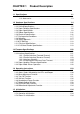
CHAPTER 1 Product Description Table of Contents 1.1 Specifications 1-1 1.1.1 Features. . . . . . . . . . . . . . . . . . . . . . . . . . . . . . . . . . . . . . . . . . . . . . . 1-1 1.1.2 Accessories . . . . . . . . . . . . . . . . . . . . . . . . . . . . . . . . . . . . . . . . . . . . 1-3 1.2 Hardware Specifications 1-4 1.2.1 Printing Method . . . . . . . . . . . . . . . . . . . . . . . . . . . . . . . . . . . . . . . . . . . . . . 1-4 1.2.2 Printing Specifications . . . . . . . . . . . . . . . . . . .
1.6 MAIN COMPONENTS 1.6.1 C166 MAIN Board Assembly . . . . . . . . . . . . . . . . . . . . . . . . . . . . . . . . . 1.6.2 C166 PSB/PSE Board Assembly . . . . . . . . . . . . . . . . . . . . . . . . . . . . . . 1.6.3 C165 PNL Board Assembly . . . . . . . . . . . . . . . . . . . . . . . . . . . . . . . . . . 1.6.4 Printer Mechanism . . . . . . . . . . . . . . . . . . . . . . . . . . . . . . . . . . . . . . . . . 1.6.5 Housing Assembly. . . . . . . . . . . . . . . . . . . . . . . . . . . . . . . . . . . . . .
List of Tables Table 1-1. Items Included with the Printer . . . . . . . . . . . . . . . . . . . . . . . . . . . . . . 1-3 Table 1-2. Consumables . . . . . . . . . . . . . . . . . . . . . . . . . . . . . . . . . . . . . . . . . . . 1-3 Table 1-3. Optional Units . . . . . . . . . . . . . . . . . . . . . . . . . . . . . . . . . . . . . . . . . . . 1-3 Table 1-4. Print Speed and Printable Columns . . . . . . . . . . . . . . . . . . . . . . . . . . 1-5 Table 1-5. Print Resolution . . . . . . . . . . . . . . . .
FX-2170 Service Manual Product Description 1.1 Specifications These specifications provide statistical information for the the FX-2170 serial impact dot matrix printer. 1.1.1. Features The FX-2170 is a 9-pin serial impact dot-matrix printer suitable for the VAR (value added reseller) market.
Product Description FX-2170 Service Manual Figure 1-1 Exterior View of the FX-2170 1-2 Rev.
FX-2170 Service Manual Product Description 1.1.2.
Product Description FX-2170 Service Manual 1.2 Hardware Specifications This section provides detailed hardware specifications for the FX-2170. 1.2.1 Printing Method Printing method Impact dot matrix Color Black Number of pins 18 pins Pin arrangement 9×2 Pin diameter 0.29 mm (0.0114 inch) 2.822 mm (8/72") #1 #2 #3 #4 #5 #6 #7 #8 #9 #10 #11 #12 #13 #14 #15 #16 #17 #18 0.353 mm (1/72’’) Head Center 0.
FX-2170 Service Manual Product Description 1.2.
Product Description FX-2170 Service Manual 1.2.3 Paper Handling Specifications Feeding method Friction feed Push tractor feed Push and pull feed (front, rear) (front, rear) (front, rear, bottom) Feeder Front push tractor, rear push tractor, CSF bin 1 /bin 2 (optional) tractor (optional) and roll paper holder (optional) Paper path Manual insertion CSF Tractor Line spacing 1/6 inch or programmable in increments of 1/216 inch.
FX-2170 Service Manual Paper thickness lever Product Description Set the paper thickness lever to the appropriate position, as indicated in the following table. Table 1-7 Paper Thickness Lever Positions Paper Thickness ( inches) Paper Thickness (mm) Lever Position Minimum Maximum Minimum Maximum 0 0.0024 0.0043 0.06 0.11 1 0.0043 0.0067 0.11 0.17 2 0.0070 0.0075 0.18 0.19 3 0.0079 0.0098 0.20 0.25 4 0.0098 0.0122 0.25 0.31 5 0.0126 0.0150 0.32 0.38 6 0.0153 0.0181 0.
Product Description FX-2170 Service Manual 4. Push-pull tractor feed Set the release lever to the REAR PUSH/FRONT PUSH position. Load paper from the front or rear entrance. the paper eject assembly and attach the pull tractor unit. any slack in the paper between the platen and pull tractor. horizontal position of the pull tractor and push tractor. carbonless. greater than 1/6 inch. after the paper end has been detected.
FX-2170 Service Manual Printable area Product Description Figure 1-3 shows the printable area for cut sheets. The table below defines the abbreviations used in the figure. Table 1-10 Printable Area for Cut Sheets Abbreviations Single Sheet Multipart PW (width) Refer to Table 1-8. Refer to Table 1-9. PL (length) Refer to Table 1-8. Refer to Table 1-9. LM (left margin) 3 mm (0.12") or more (PW ≤ 364 mm (14.33")) 25 mm (0.98") or more (PW = 420 mm (16.5")) 3 mm (0.12") or more (PW ≤ 364 mm (14.
Product Description FX-2170 Service Manual Envelopes and Card Stock Paper/media specifications The following tables gives specifications for envelopes and card stock. Table 1-11 Specifications for Envelopes Front Entry Minimum Rear Entry Maximum Minimum Maximum No. 6 envelopes Width —- 166 mm (6.5") Length —- 92 mm (3.6") No. 10 envelopes Width —- 240 mm (9.5") Length —- 104 mm (4.1") Total thickness —— —— —— 0.52 mm (0.
FX-2170 Service Manual Printable area Product Description The figure below shows the printable area for envelopes and card stock. Each abbreviation is defined in the following table. Table 1-13 Printable Area for Envelopes and Card Stock Abbreviations Envelopes Card Stock PW (width) Refer to Table 1-11. Refer to Table 1-12. PL (length) Refer to Table 1-11. Refer to Table 1-12. LM (left margin) 3 mm (0.12") or more 3 mm (0.12") or more RM (right margin) 3 mm (0.12") or more 3 mm (0.
Product Description FX-2170 Service Manual Continuous Paper Paper/media specifications The following table gives specifications continuous paper. Table 1-14 Specifications for Continuous Paper (Single Sheet and Multipart) Front Entry Rear Entry Bottom Entry Minimum Maximum Minimum Maximum Minimum Maximum Width 101 mm (4.0") 406 mm (16") 101 mm (4.0") 406 mm (16") 101 mm (4.0") 406 mm (16") Length 101 mm (4.0") 559 mm (22") 101 mm (4.0") 559 mm (22") 101 mm (4.
FX-2170 Service Manual Printable area Product Description The figure below shows the printable area for continuous paper. Each abbreviation is defined in the following table. Table 1- 15 Printable Area for Continuous Paper Abbreviations Continuous Paper PW (width) Refer to Table 1-14. PL (length) Refer to Table 1-14. LM (left margin) 13 mm (0.51") or more RM (right margin) 13 mm (0.51") or more TM (top margin) 4.2 mm (0.17") or more BM (bottom margin) 4.2 mm (0.
Product Description FX-2170 Service Manual Continuous Paper with Labels Paper/media specifications The following table gives the specifications for continuous paper with labels. Table 1-16 Specifications for Continuous Paper with Labels Front Entry Minimum Label size Rear Entry Maximum Minimum See the figure below Bottom Entry Maximum —- Minimum Maximum See the figure below Base sheet width 101 mm (4.0") 406 mm (16") —- —- 101 mm (4.
FX-2170 Service Manual Product Description Roll Paper Note: Roll paper is not available in all models, and not available in the U.S. Paper/media specifications The following table shows specifications for roll paper. Table 1-17 Specifications for Roll Paper Front Entry Minimum Rear Entry Maximum Minimum Maximum Width —— 216 mm (8.5") Length —— —— Thickness —— —— 0.07 mm (0.0028") 0.09 mm (0.0035") Weight —— —— 52.3 g/m2 (14 lb) 82 g/m2 (22 lb) Quality Plain paper, recycled paper.
Product Description FX-2170 Service Manual 1.2.5 Ribbon Specifications Table 1-19 Statistics on the Ribbon Item Specification Type Fabric Color Black Ribbon life 12 million characters (draft, 10 cpi, 14 dots/ character) Dimension 506.0 mm (W) × 123.5 mm (D) × 23.0 mm (H) 19.92" (W) x 4.86" (D) x .91" (H) 1.2.6 Electrical Specifications Tables 1-20 and 1-21 provide statistics on electrical ratings and consumption.
FX-2170 Service Manual Product Description 1.2.7 Environmental Conditions Table 1-22 explains the conditions the printer requires during operation and when not operating.
Product Description FX-2170 Service Manual 1.2.10 CE Marking The following table lists CE marking information. Table 1-25 CE Marking Low Voltage Directive 73/23 / EEC EN60950 EMC Directive 89/336 / EEC EN55022 class B EN50082-1 , IEC801-2 IEC801-3 , IEC801-4 Non-Automatic Weighing Instruments Directive 90/384/EEC EN45501 1.2.11 Physical Specifications Table 1-26 provides printer dimensions and weight. Table 1-26 Physical Specifications Dimensions 639 mm (W) × 410 mm (D) × 257 mm (H) 25.
FX-2170 Service Manual Product Description Stacker capacity Table 1-28 Capacity of the Stacker CSF Bin 1 CSF Bin 2 Single sheets 140 sheets (❇ 1) 100 sheets (❇ 2) ——- Envelopes 15 sheets (❇ 3) 28 sheets (❇ 4) ——- Card stock 30 sheets (❇ 5) ——- Multipart 36 sheets (❇ 6) ——- ❇ 1: ❇ 2: ❇ 3: ❇ 4: ❇ 5: ❇ 6: Single sheets (weight: 82 g/m2, 22 lb), except for A3 paper Single sheets (weight: 82 g/m2, 22 lb), A3 paper Envelopes (weight: 91 g/m2, 24 lb) Envelopes (weight: 45 g/m2, 12 lb) Card stock
Product Description FX-2170 Service Manual 1.3 Firmware Specifications This section provides detailed information about FX-2170 firmware. 1.3.1 Control Codes and Fonts Control codes ESC/P and IBM 2380/2381 plus emulations.
FX-2170 Service Manual Product Description 1.3.2 Interface Specifications This printer provides a bidirectional 8-bit parallel interface and a Type B optional interface slot, standard. 1.3.2.
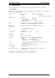
Product Description FX-2170 Service Manual DATA data byte n+1 data byte n t h old STROBE tsetup tstb tnext BUSY tready tb u s y ACKNLG trep ly tack tn b u s y Figure 1-8 Data Transmission Timing Table 1-32 Maximum and Minimum Timings for Data Transmission Parameter Minimum Maximum setup 500 nsec ——- thold 500 nsec ——- t stb 500 nsec ——- tready 0 ——- tbusy —— 500 nsec treply —— ——- tack 500 nsec 10 µs tnbusy 0 ——- tnext 0 ——- ttout —— 120 nsec ttin —— 200 nse
FX-2170 Service Manual Product Description 1.3.2.
Product Description • Extensibility request • Device ID FX-2170 Service Manual The printer responds to the extensibility request in the affirmative, when the request is 00 H or 04 H, which means: 00 H Request nibble mode of reverse channel transfer. 04 H Request device ID in nibble mode of reverse channel transfer. Refer to the following descriptions: ESC/P [00 H][31 H] .......... MFG: EPSON, CMD: ESC/P9-84, MDL: FX-2170, CLS: PRINTER IBM 2381 Plus [00 H][32 H] ..........
FX-2170 Service Manual Product Description 1.3.3 Paper Handling Sequence In this section, paper handling firmware sequences are described in several cases. • Printer status Printer is on line (not in the pause state). No PE sensor detects that paper is loaded. The release lever position is set to continuous paper. Table 1-34 Paper Handling Sequence 1 Occurrence Result Print command sent Continuous paper is loaded. Pause button pressed Printer enters pause state.
Product Description • Printer status FX-2170 Service Manual The front PE sensor detects that paper is loaded in the front paper path. The release lever is set to continuous paper Table 1-36 Paper Handling Sequence 3 Occurrence Result PAUSE button pressed Printer goes off or on line. LF/FF button pressed Printer performs a line feed. LF/FF button held down continuously The printer performs a form feed after the line feed.
FX-2170 Service Manual • Printer status Product Description The rear PE sensor detects that paper is loaded in the rear paper path. Release lever position is set to Friction. Table 1-38 Paper Handling Sequence 5 Occurrence Result Pause button pressed Printer goes on or off line. LF/FF button pressed Printer performs a line feed. LF/FF button held down continuously Printer ejects paper forward after the line feed (except with roll paper).
Product Description FX-2170 Service Manual 1.3.4. Paper Width (PW) Sensor Operation The PW sensor is mounted on the ribbon mask holder to measure the paper width and detect the top edge of the paper. However, in cases where print data is over the paper width, the image cut function does not operate in all modes. This section describes when the image cut function is operational, as shown in the following table.
FX-2170 Service Manual Product Description 1.4 Operating Instructions This section provides detailed information about the FX-2170 control panel buttons and LEDs. 1.4.1 Control Panel Operations The printer control panel contains 6 non-lock type pushbuttons and 9 LEDs for various printer functions. The exterior view of the control panel is shown in the following figure.
Product Description FX-2170 Service Manual Operations at power on Turning the printer on while pressing panel buttons executes the functions below: Table 1-42 Operation at Power On Button Function Load / Eject LQ self-test LF / FF Draft self-test Load / Eject and LF / FF Pitch Hexadecimal data dump Default setting Font and Tear Off / Bin Clear EEPROM Pause Bi-d adjustment Others Not available Operation in default setting mode The buttons used in default setting mode are as follows: Table 1
FX-2170 Service Manual Product Description 1.4.3 Micro Adjust Function The micro adjust function lets you set the TOF and tear off positions. After the printer is put in this mode, you can adjust the top of form (TOF) position up or down in increments of 1⁄216 inch by pressing the LF/FF or Load/Eject button. The adjusted TOF position is saved to the EEPROM. If the printer is turned off, the setting is not cleared.
Product Description FX-2170 Service Manual 1.4.5 Self-test Function Pressing the Load / Eject button while turning on the printer puts the printer in LQ self-test mode. Pressing the LF/FF button while turning on the printer puts the printer in Draft self-test mode. You can stop the self-test temporarily by pressing the Pause button, and you can exit the self-test mode by turning off the printer. When pages are printed from the CSF, the first sheet is used for scaling the sheet length.
FX-2170 Service Manual Product Description 1.4.7 Default Setting Function Pressing the Pitch button while turning on the printer puts the printer in default setting mode. Some default printer settings can be changed in this operation. The method for setting defaults is described in the instruction sheets, which are printed out immediately after you enter the mode.
Product Description FX-2170 Service Manual 1.4.9 Bidirectional Adjustment Function Pressing the Pause button while turning on the printer puts the printer in bidirectional adjustment mode. In this mode, you can adjust the bidirectional alignment for the following three modes: 1. High-speed draft mode 2. Draft mode 3. LQ mode For instructions on performing the adjustment, see Chapter 4. 1.5 Initialization 1.5.1 Software Initialization This initialization is activated by the control code ESC@.
FX-2170 Service Manual Product Description 1.6 MAIN COMPONENTS The main components of the FX-2170 are designed for easy removal and repair. main components are: The ❒ C166 MAIN Board Assembly ❒ C166 PSB/PSE Board Assembly (120 V/230 V) ❒ C165 PNL Board Assembly ❒ Printer Mechanism ❒ Housing Assembly The following figure shows the main components of the FX-2170. Figure 1-12 Main Components Rev.
Product Description FX-2170 Service Manual 1.6.1 C166 MAIN Board Assembly The C165 MAIN board consists of a TMP96C041AF CPU, an E05B13 gate array, a program/CG ROM, a PS-RAM, an EEPROM, etc. IC11 PF Motor Driver UDN2917EB IC3 P-ROM IC 5 PS RAM IC 2 GATE ARRAY E05B13 IC12 CR Motor Driver SLA7024M Head Drive TRANSISTOR IC 1 CPU TMP96C041AF EEPROM CN2 for Option I / F Figure 1-13 C166 MAIN Board Assembly 1.6.
FX-2170 Service Manual Product Description 1.6.3 C165 PNL Board Assembly This board function is the control panel for the FX-2170. It consists of a power switch, six buttons, and nine indicator LEDs. This board is almost same as it for the LQ-2170. SW LED LED SW SW LED LED SW SW LED SW Power SW Figure 1-15 Board Assembly C165 PNL 1.6.
Product Description FX-2170 Service Manual 1.6.5. Housing Assembly This consists of printer cover assembly, edge guide assembly, upper housing, lower housing assembly, etc. Figure 1-17 Housing Assembly 1-38 Rev.
CHAPTER 2 Operating Principles Table of Contents 2.1 PRINTER MECHANISM OPERATION 2-1 2.1.1 Printing Mechanism . . . . . . . . . . . . . . . . . . . . . . . . . . . . . . . . . . . . . . . . . . 2-1 2.1.2 Carriage Movement Mechanism . . . . . . . . . . . . . . . . . . . . . . . . . . . . . . . . 2-2 2.1.3. Platen Gap Adjustment . . . . . . . . . . . . . . . . . . . . . . . . . . . . . . . . . . . . . . . 2-3 2.1.4 Paper Handling Mechanism . . . . . . . . . . . . . . . . . . . . . . . . . . . . . . . . . .
List of Figures Figure 2-1. Printhead Operation . . . . . . . . . . . . . . . . . . . . . . . . . . . . . . . . . . . . . 2-1 Figure 2-2. Carriage Movement Mechanism. . . . . . . . . . . . . . . . . . . . . . . . . . . . 2-2 Figure 2-3. Platen Gap Adjust Lever . . . . . . . . . . . . . . . . . . . . . . . . . . . . . . . . . . 2-3 Figure 2-4. Release Switch . . . . . . . . . . . . . . . . . . . . . . . . . . . . . . . . . . . . . . . . . 2-4 Figure 2-5. Friction Advance Operation Using the Top Entrance . .
FX-2170 Service Manual Operating Principles 2.1 PRINTER MECHANISM OPERATION This section describes the printer mechanism and explains how it works. 2.1.1 Printing Mechanism The printing mechanism is composed of the printhead, ink ribbon, and ribbon mask. The printhead is an 18-pin (9 pins × 2) head for impact dot printing. To improve the durability of the dot wires, they are arranged on the printhead in 2 columns.
Operating Principles FX-2170 Service Manual 2.1.2 Carriage Movement Mechanism The carriage movement mechanism consists of the carriage assembly, carriage (CR) motor, timing belt, driven pulley, home position (HP) sensor, etc. The CR motor drives the timing belt. The carriage assembly is connected to the timing belt, which is moved by the CR motor. Figure 2-2 shows the carriage movement mechanism. The printer detects the carriage home position with the HP sensor.
FX-2170 Service Manual Operating Principles 2.1.3 Platen Gap Adjustment You can adjust the platen gap (the gap between the platen and printhead) to allow the printer to use paper of different weights or thicknesses. When you move the platen gap adjust lever forward or backward, the carriage guide shaft rotates. This rotation moves the carriage either toward or away from the platen and changes the platen gap.
Operating Principles FX-2170 Service Manual 2.1.4. Paper Handling Mechanisms During the normal operation, paper is fed to the printer, advanced to the specified position, and ejected from the printer. These paper-handling operations are performed by various paper handling mechanisms, such as tractors, platens, rollers, and gears. This section describes the printer’s paper handling mechanisms. 2.1.4.1.
FX-2170 Service Manual Operating Principles 2.1.4.2. Paper Advance Mechanism This section describes how the friction and tractor advance mechanisms work to move the paper through the printer. 1. Friction Advance Method Paper is held between the platen and the paper guide rollers and between the paper tension roller and paper tension unit cover. The paper feed (PF) motor pinion gear, turns in the direction of the black arrow, driving the paper advance reduction gear.
Operating Principles FX-2170 Service Manual 2. Push Tractor Method The push tractor method is used with the rear or front entrance. When the push tractor method is used with the rear entrance, the torque generated by the PF motor is transmitted to the push tractor gear through the PF motor pinion gear, paper advance reduction gear, and tractor reduction gear.
FX-2170 Service Manual Operating Principles Figure 2-7. Push Tractor Operation Using the Front Paper Entrance Rev.
Operating Principles FX-2170 Service Manual 3. Pull Tractor Method The pull tractor advances paper in basically the same way as the push tractor. The push tractor is installed at the paper entrance and pushes paper into the printer. On the other hand, the pull tractor is installed at the paper exit and pulls paper out of the printer mechanism. As a result, the paper tension unit is not required. Figure 2-8 illustrates pull tractor operation when paper is fed through the bottom paper entrance.
4. Push-Pull Tractor Method The push-pull tractor method is a combination of the push and pull tractor methods. Two tractors are used to advance the paper: one at the front paper entrance and the other at the rear paper entrance. They operate simultaneously to push and pull the paper through the printer mechanism. Figure 2-9 illustrates push-pull tractor operation when paper is fed through the rear paper entrance.
Operating Principles FX-2170 Service Manual Figure 2-10 Push-Pull Tractor Operation Using the Front Paper Entrance 2-10 Rev.
FX-2170 Service Manual Operating Principles 2.1.5 Paper Paths This section describes various paper paths through the printer mechanism. These paper paths are divided into four groups, depending on which entrance (top, rear, bottom, or front) is used to feed paper. The printer has two PE (paper end) sensors. The front PE sensor is located in front of the printer mechanism. The rear PE sensor is located behind the printer mechanism. Refer to the following figure.
Operating Principles FX-2170 Service Manual 2. Rear Entrance Figures 2-13, 2-14, and 2-15 show the paper paths for tractor feeding using the rear entrance. You can use the rear entrance with any of the following paper feed methods: push tractor feed, pull tractor feed, or push-pull tractor feed. When you use the rear entrance, the rear PE sensor detects when paper is out. Down Figure. 2-13. Push Tractor Feeding Using the Rear Entrance Down Figure. 2-14.
FX-2170 Service Manual Operating Principles Figure 2-15. Push-Pull Tractor Feeding Using the Rear Entrance As shown above in Figure 2-15, when you use the pull tractor with this printer, you must remove the paper eject cover, which includes the paper tension roller, from the printer mechanism. 3. Bottom Entrance Figure 2-16 shows the paper path for tractor feeding using the bottom entrance. The bottom entrance is used only for pull tractor feed.
Operating Principles FX-2170 Service Manual 4. Front Entrance Figures 2-17 through 2-20 show the paper paths for the front entrance. The front entrance can be used with any of the following paper feed methods: friction feed, push tractor feed, pull tractor feed, or push-pull tractor feed. When the front entrance is used, the front PE sensor detects when paper is out. Figure 2-17 Friction Feeding Using the Front Entrance Up Up Figure 2-18 Push Tractor Feeding Using the Front Entrance 2-14 Rev.
FX-2170 Service Manual Operating Principles Down Figure 2-19 Pull Tractor Feeding Using the Front Entrance Figure 2-20 Push-Pull Tractor Feeding Using the Front Entrance Rev.
Operating Principles FX-2170 Service Manual 2.1.6 Ribbon Advance Mechanism The ribbon is held between the ribbon advance roller (ribbon driven gear) and the ribbon pressure roller. When the carriage moves from left to right and vice versa on the CR guide shaft, the timing belt turns the belt-driven pulley. Then the torque is transmitted to the ribbon driving gear through the gear trains.
FX-2170 Service Manual Operating Principles 2.2 POWER SUPPLY OPERATION The printer can be powered by either of two power supply boards: the C166 PSB (120 V) or C166 PSE (230 V) power supply. These boards are the same for both the LQ-2170 and FX-2170. Additionally, the PSB and PSE boards function the same, except for a difference in primary circuitry. The power supply board outputs the DC current necessary to drive the printer control circuits and drive mechanism.
Operating Principles FX-2170 Service Manual 2.2.2 Power Supply Circuit Operation The power supply circuit is composed of an RCC (ringing choke converter) system and the power switch circuit in the secondary circuitry. The power supply circuit has several protection and control circuits. This section describes these circuits. 1. Power Switch Circuit The power switch circuit is in the secondary circuitry. It is shown in the illustration below.
FX-2170 Service Manual Operating Principles 3. +35 V Constant Voltage Control Circuit The +35 V constant voltage control circuit is illustrated below. 11 C15 C13 Q1 R11 10+ +35V Line R20 R15 R21 Q3 Q2 R19 R16 ZD51 ZD81 ZD82 ZD83 ZD84 ZD85 R13 R14 C12 + IC1 9+ GND Line R56 8 1 7 2 D81 R57 Figure 2-25 +35 V Line Constant Voltage Control Circuit The constant voltage control circuit operates to keep the 35 V line at 35 V ± 6 %. When the voltage between ZD51 and ZD85 becomes 32.7 V ± 2.
Operating Principles FX-2170 Service Manual 5. +35 V Line Over Current Protection Circuit The +35 V line over current control circuit is illustrated below. R54 +35V Line R70 D85 Q53 R71 R72 R73 GND C57 R74 Q31 R75 3 6 Q54 4 R68 5 Q82 PSC Figure 2-27 +35 V Line Over Current Protection Circuit When the +35 V line becomes less than 27 V, Q82 and Q54 turn on, and PC1 turns on. Consequently, Q32 and Q31 turn off, and then switching FET Q1 shuts off.
FX-2170 Service Manual Operating Principles 7. +5 V Line Constant Voltage Control Circuit The +5 V line constant voltage control circuit is shown below. +35V R81 R60 R59 L51 Q51 GND R53 +5v Line ZD55 R88 R61 GND R51 D51 16 R64 + 15 - 8 R65 GND IC51 TL494CN Figure 2-29 +5 V Line Constant Voltage Control Circuit Port 16 of IC51 (TL494CN) monitors the + 5 V line, and the voltage is compared with the standard voltage, which is input into port 15. When the voltage of port 16 goes below 4.
Operating Principles FX-2170 Service Manual 2.3 CONTROL CIRCUIT The control circuit consists of the C166 MAIN board assembly and C165 PNL board This section describes the major components and explains how the boards work. 2.3.1 Overview of Control Circuit Operation The printer’s control circuit includes a TMP96C041AF CPU that runs at 14.74 MHz, an E05B13YA gate array, a 1M bit PS-RAM (8-bit bus, less than 80ns) , a 2M bit PROM (8-bit bus, less than 120ns), and other circuits.
FX-2170 Service Manual Operating Principles The following figure shows the data flow from the host computer to the printhead. Data sent from the host computer is converted to image data and transmitted to the printhead through the gate array.
Operating Principles FX-2170 Service Manual 2.3.2 System Reset Circuit Control circuits IC1 and IC2 are initialized when a RESET signal (LOW level) is output from port 1 (VOUT) of IC10. IC10 monitors the +5 V line on port 3, and resets under the following conditions: E05813YA IC2 +5V RESET 61 R47 1K IC10 PST5920 IC1 TPM96C041AF +5V VOUT 1 23 RESET MRES 2 VCC 3 GND 4 C16 0.1U Figure 2-32 Reset Circuit 1. When the power supply is turned on, a RESET signal is output.
FX-2170 Service Manual Operating Principles 2.3.4 CR Motor Driver Circuit The CR motor driver circuit is shown below.
Operating Principles FX-2170 Service Manual 2.3.5 PF Motor Driver Circuit The figure below shows the PF motor driver circuit.
FX-2170 Service Manual Operating Principles 2.3.7 Sensor Circuits The CPU detects conditions of the following sensors: home position (HP) sensor, release sensors 1 and 2, platen gap (PG) sensors 1 and 2, rear and front paper end (PE) sensors, paper width (PW) sensor, and cover open sensor.
CHAPTER 3 Disassembly and Assembly Table of Contents 3.1 OVERVIEW 3.1.1 Precautions. . . . . . . . . . . . . . . . . . . . . . . . . . . . . . . . . . . . . . . . . . . . . . . . . 3.1.2 Tools . . . . . . . . . . . . . . . . . . . . . . . . . . . . . . . . . . . . . . . . . . . . . . . . . . . . . . 3.1.3 Service Checks After Repair . . . . . . . . . . . . . . . . . . . . . . . . . . . . . . . . . . . 3.1.4 Specifications for Screws . . . . . . . . . . . . . . . . . . . . . . . . . . . . . . . . . . . . .
List of Figures Figure 3-1. Screw Types and Abbreviations . . . . . . . . . . . . . . . . . . . . . . . . . . . . 3-3 Figure 3-2. Flowchart for Disassembling the Printer . . . . . . . . . . . . . . . . . . . . . . 3-4 Figure 3-3. Before Starting Disassembly Procedures . . . . . . . . . . . . . . . . . . . . . 3-5 Figure 3-4. Removing the Panel Board Assembly . . . . . . . . . . . . . . . . . . . . . . . 3-6 Figure 3-5. Lock Cover for CN1 and the FFC . . . . . . . . . . . . . . . . . . . . . . . . . . .
Figure 3-50. Removing the Right CSF Cover. . . . . . . . . . . . . . . . . . . . . . . . . . . Figure 3-51. Engaging 5 Gears . . . . . . . . . . . . . . . . . . . . . . . . . . . . . . . . . . . . . Figure 3-52. Removing the E-ring and 2 CBS Screws. . . . . . . . . . . . . . . . . . . Figure 3-53. Removing the Paper Feed Roller Cover . . . . . . . . . . . . . . . . . . . . 3-31 3-31 3-32 3-32 List of Tables Table 3-1. Recommended Tools . . . . . . . . . . . . . . . . . . . . . . . . . . . . . . . . . . .
FX-2170 Service Manual Disassembly and Assembly 3.1 OVERVIEW This section describes various points to note when disassembling and assembling the printer. 3.1.1 Precautions Follow the precautions below for disassembly or assembly. WARNING Before disassembling, assembling, or adjusting the printer, disconnect the power supply cable from the AC power socket. Failure to do so can cause physical injury. The power switch is wired in the secondary circuitry.
Disassembly and Assembly FX-2170 Service Manual 3.1.3 Service Checks After Repair Before returning the printer after service, use the check list in Table 3-3, which provides a record to make servicing and shipping more efficient. Table 3-3.
FX-2170 Service Manual Disassembly and Assembly 3.1.4 Specifications for Screws Table 3-4 lists the abbreviations used in the following sections for small parts, such as screws and washers. Table 3-4.
Disassembly and Assembly FX-2170 Service Manual 3.2. PRINTER DISASSEMBLY AND ASSEMBLY This section describes procedures for disassembling and assembling the main components of the printer. When the procedure for installing a component is simply the reverse of removing the component, this chapter does not describe the assembly procedure. If necessary, special notes on assembling or adjusting a component are given at the end of the description of each procedure.
3.2.1. Before Starting Disassembly Procedures 1. Remove the following parts: . Front edge guide assembly Front cover Rear edge guide assembly Printer cover Front/rear tractor assembly Ribbon cartridge Bottom cover Paper eject assembly Refer to the following figure. Note Remove the paper eject cover and the front/rear tractor assembly by pushing to release the hooks at both sides. When remounting them, be sure to snap the hooks on the projecting parts.
Disassembly and Assembly FX-2170 Service Manual 3.2.2. Removing the Panel Board Assembly 1. Remove the printer cover and ribbon cartridge (see Section 3.2.1). 2. Release the left clips for the panel board assembly by pushing them from the cutout located on the inside front of the upper housing assembly. 3. Release the flexible flat cable (FFC) by pulling the lock cover for CN1, and then disconnect the FFC for CN1 and connector CN2 from the C165 PNL board assembly.
3.2.3. Removing the Printhead 1. Remove the printer cover and ribbon cartridge (see Section 3.2.1). 2. Remove 2 CBS screws (3 × 10, F/Zn) securing the printhead to the CR assembly. 3. Remove the printhead from the CR assembly. 4. Disconnect 2 wide FFCs from the printhead and then disconnect the narrow FFC from the connector on the CR cover. Assembly Notes The FFC must be connected properly, as shown in the following figure.
Disassembly and Assembly FX-2170 Service Manual 3.2.4 Removing the HP Sensor 1. Remove the printer cover, ribbon cartridge, front edge guide, and front cover (see Section 3.2.1). 2. Disconnect the connector cable for the HP sensor. 3. Remove the HP sensor by pushing up and releasing the 2 clips at the bottom of the HP sensor from the front paper entrance. 2 Clips for HP Sensor Figure 3-8 Removing the HP Sensor Assembly Note Notice the direction for mounting the HP sensor.
FX-2170 Service Manual Disassembly and Assembly Assembly Notes Mount the PW sensor assembly onto the ribbon mask holder groove, aligning the bottom line of micro photo sensor to the bottom line of the groove. Whenever you remove the PW sensor assembly, clean the surface of the sensor by wiping it with a soft material. If the surface is not clean, abnormal operations may occur, such as printing on the platen surface. The tightening torque for the CB screw (2.5 × 5, F/Zn) = 0.08 ~ 0.12 Nm (0.8 ~ 0.
Disassembly and Assembly FX-2170 Service Manual 3.2.6 Removing the Platen Assembly 1. Remove the printer cover, ribbon cartridge, and platen knob (see Section 3.2.1). 2. Release both locks for the left and right bushings (8 mm) by pushing the lever holder for the bushings outside, and then pulling the holder lever forward. Left and Right Bushings (8mm) Figure 3-11 Releasing the Locks for the Bushings 3 Slide the platen assembly to the right, and move the printhead to the right edge. 4.
FX-2170 Service Manual Disassembly and Assembly 3.2.7 Removing the Upper Housing Assembly 1 Remove the rear edge guide assembly, paper eject assembly, rear tractor unit, and printer cover (see Section 3.2.1). 2. Remove the panel board assembly (see Section 3.2.2). 3. Remove 4 CBB screws (4 × 14, F/Zn) securing the upper housing assembly. 4. Remove the platen knob. 5.
Disassembly and Assembly FX-2170 Service Manual 3.2.8 Removing the Case Open Sensor Assembly 1. Remove the rear edge guide assembly, paper eject assembly, rear tractor unit, and printer cover (see Section 3.2.1). 2. Remove the panel board (see Section 3.2.2) and upper housing assemblies (see Section 3.2.7). 3. Turn the upper housing assembly over and remove the case open sensor assembly by loosening the CBB screw ( 3 × 8, F/Zn) fixing the sensor holder to the upper housing assembly. C.B.
FX-2170 Service Manual Disassembly and Assembly 3.2.10 Removing the Printer Mechanism 1. Remove the rear/front edge guide assembly, front cover, paper eject assembly, rear/front tractor units, and printer cover (see Section 3.2.1). 2. Remove the panel board assembly (see Section 3.2.2) and upper housing assembly (see Section 3.2.7). 3. Remove 4 printer mechanism mounting screws securing the printer mechanism. 4.
Disassembly and Assembly FX-2170 Service Manual 3.2.10.1 Removing the PF Motor 1. Remove the rear/front edge guide assembly, front cover, paper eject assembly, rear/front tractor unit, and printer cover (see Section 3.2.1). 2. Remove the panel board (see Section 3.2.2) and upper housing assemblies (see Section 3.2.7). 3. Remove the printer mechanism (see Section 3.2.10). 4. Remove the CBS screw (3 × 6, F/Zn) and CB screw (3 × 8, F/Zn) securing the PF motor. 5.
FX-2170 Service Manual Disassembly and Assembly 3.2.10.2 Removing the PG Sensor Assembly 1. Remove the rear/front edge guide assembly, front cover, paper eject assembly, rear/front tractor unit, and printer cover (see Section 3.2.1). 2. Remove the panel board (see Section 3.2.2) and upper housing assemblies (see Section 3.2.7). 3. Remove the printer mechanism (see Section 3.2.10 ). 4. Remove the hexagon nut (standard, M4) securing the PG sensor assembly to the right frame assembly.
Disassembly and Assembly FX-2170 Service Manual 3.2.10.3 Removing the Right Frame Assembly 1. Remove the rear/front edge guide assembly, front cover, paper eject assembly, rear/front tractor unit, and printer cover (see Section 3.2.1). 2. Remove the panel board (see Section 3.2.2) and upper housing assemblies (see Section 3.2.7). 3 Remove the printer mechanism (see Section 3.2.10 ), CR motor assembly (see Section 3.2.9), PF motor, (see Section 3.2.10.1) and PG sensor assembly (see Section 3.2.10.2 ).
FX-2170 Service Manual Disassembly and Assembly 2. Remove the right sub frame from the right frame assembly. 3. Remove the following 11 parts from the right frame assembly. 2 compression springs (200 g) 2 plain washers 1 spur gear (27 mm) 2 spur gears (34.5 mm) 1 spur gear (34 mm) 1 spur gear (21 mm) 1 combination gear (8 mm, 31.5 mm) 1 intermittent gear Assembly Notes Adjust the bidirectional print alignment. Refer to Chapter 4.
Disassembly and Assembly FX-2170 Service Manual Assembly Notes When you engage the release lever and release lever transmission to the tractor clutch cam, notice the points in the following figure. The tightening torque for the CBS screws (3 × 6, F/Zn) and (3 × 8, F/Zn) 0.78 ~ 0.98 N.m (8 ~ 10 Kg - cm) The tightening torque for the hexagon nut (standard, M4) 1.18 ~ 1.37 N.m(12 ~ 14 Kg f - cm) = Notice how the intermittent gear, release lever, and release lever transmission are engaged.
FX-2170 Service Manual Disassembly and Assembly 3.2.10.5 Removing the Left Frame Assembly 1. Remove the rear/front edge guide assembly, front cover, paper eject assembly, rear/front tractor unit, and printer cover (see Section 3.2.1). 2. Remove the panel board assembly (see Section 3.2.2), upper housing assembly (see Section 3.2.7), and then remove the printer mechanism (see Section 3.2.10 ). 3. Remove 2 CBS screws (3 × 6, F/Zn) securing the platen cover. 4.
Disassembly and Assembly FX-2170 Service Manual 3.2.10.6 Removing the Ribbon Drive (RD) Assembly 1. Remove the rear/front edge guide assembly, front cover, paper eject assembly, rear/front tractor unit, and printer cover (see Section 3.2.1). 2. Remove the panel board (see Section 3.2.2) and upper housing assemblies (see Section 3.2.7). 3. Remove the printer mechanism (see Section 3.2.10). 4. Remove the left frame assembly (see Section 3.2.10.5). 5.
FX-2170 Service Manual Disassembly and Assembly 3.2.10.7 Removing the CR Assembly 1. Remove the rear/front edge guide assembly, front cover, paper eject assembly, rear/front tractor unit , and printer cover. 2. Remove the panel board (see Section 3.2.2) and upper housing assemblies (see Section 3.2.7) . 3. Remove the printer mechanism (see Section 3.2.10 ). 4. Remove the left frame assembly (see Section 3.2.10.5) and RD assembly (see Section 3.2.10.6). 5.
Disassembly and Assembly FX-2170 Service Manual Assembly Notes Insert the timing belt properly into the 2 holding slots at the bottom of the CR assembly. Take up the timing belt slack between the two slots completely, as shown in the following figure. Insert the 2 oil pads into the proper positions in the CR assembly, as shown. If you remove the rear CR guide shaft along with the CR assembly, be sure to reinstall the rear CR guide shaft in the printer mechanism.
FX-2170 Service Manual Disassembly and Assembly 3.2.10.8 Removing the Rear PE Sensor Assembly 1 Remove the rear/front edge guide assembly, front cover, paper eject assembly, rear/front tractor unit, and printer cover. 2. Remove the panel board (see Section 3.2.2) and upper housing assemblies (see Section 3.2.7). 3. Remove the printer mechanism (see Section 3.2.10). 4.
Disassembly and Assembly FX-2170 Service Manual 3.2.11 Removing the C166 MAIN Board Assembly 1. Remove the rear/front edge guide assembly, front cover, paper eject assembly, rear/front tractor unit, and printer cover (see Section 3.2.1) 2. Remove the panel board (see Section 3.2.2) and upper housing assemblies (see Section 3.2.7). 3. Disconnect the following connectors from the C166 MAIN board assembly.
FX-2170 Service Manual Disassembly and Assembly 3.2.12 Removing the C166 PSB/E Board Assembly 1. Remove the rear/front edge guide assembly, front cover, paper eject assembly, rear/front tractor unit, and printer cover. 2. Remove the panel board (see Section 3.2.2) and upper housing assemblies (see Section 3.2.7). 3. Remove the 5 CBB screws (3 × 12, F/Zn) securing the C166 PSB/E board assembly. 4. Disconnect the cable for CN3 on the C166 MAIN board assembly. 5.
Disassembly and Assembly FX-2170 Service Manual 3.3. Disassembly and Assembly of CSF Bin 1 This section describes procedures for disassembling and assembling the optional cut sheet feeder. In general, you can install a component in the CSF simply by reversing the procedure for removing it. Therefore, this section does not describe assembly procedures in most cases. If necessary, special notes on assembling a component are given at the end of the description of each procedure. 3.3.
FX-2170 Service Manual Disassembly and Assembly Assembly Notes Be careful of the cable alignment for the CN1 connector cable and earth cables. Align those cables as shown in the following figure. If these cables is not aligned properly, the CSF gear cover cannot be assembled properly. Right CSF Frame Connector CN1 Connector CN2 Figure 3-41 Cable Alignment Use the following figure to assemble the 13 gears onto the right CSF frame.
Disassembly and Assembly FX-2170 Service Manual 3.3.2 Disassembling Paper Support Block Assembly 1. Remove the CSF gear cover. Refer to step 1 in Section 3.3.1. 2. Remove the stepping motor. Refer to steps 2 and 3 in the Section 3.3.1. 3. Remove the E-ring fixing the right edge of the paper feed shaft. Figure 3-43 Removing the E-ring 4. Remove 1 gear (29 mm) from the right edge of the paper feed shaft. Paper Feed Shaft Gear(29 mm) Figure 3-44 Removing 1 Gear (29mm) 5.
FX-2170 Service Manual 7. Disassembly and Assembly Remove the paper support assembly along with the paper support shaft and paper shaft holder by pulling upward. Figure 3-46 Removing the Paper Support Block Assembly 8. Remove both paper feed rollers from both paper support assemblies. 9. Remove both paper loading roller cover assemblies by releasing the clips fixing them to the paper support assembly.
Disassembly and Assembly FX-2170 Service Manual 3.3.3 Removing the Paper Eject Assembly Cover 1. Remove the paper eject assembly cover by releasing 2 clips located along both edges of the paper eject assembly cover, as shown in the following figure. Cover, Paper Eject Assy.
FX-2170 Service Manual Disassembly and Assembly 3.4 Disassembly and Assembly of CSF Bin 2 3.4.1 Disassembling the Right Side Block 1. Remove the gear train cover by releasing the 4 clips shown in the following figure. Gear Train Cover Figure 3-50 Removing the Gear Train Cover 2. Remove the following 5 gears and 1 spring from the right CSF frame. Assembly Note Pay attention how the 5 gears are engaged. Refer to the following figure.
Disassembly and Assembly FX-2170 Service Manual 3.4.2 Disassembling the Paper Support Block Assembly 1. Remove 1 E -ring fixing the paper feed roller shaft to the right CSF frame. 2. Remove 2 CTBS (3 × 8) screws securing the paper support shaft to both right and left CSF frames. E- ring CTPB Screw (3x8) Right CSF Frame Figure 3-52 Removing 1 E-ring and 2 CTBS Screws 3. Remove both paper support assemblies along with the paper feed roller shaft and paper support shaft. 4.
CHAPTER 4 Adjustments Table of Contents 4.1 ADJUSTMENT OVERVIEW 4-1 4.1.1 Required Adjustments . . . . . . . . . . . . . . . . . . . . . . . . . . . . . . . . . . . . . . . . 4-1 4.1.2. Required Adjustment Tools . . . . . . . . . . . . . . . . . . . . . . . . . . . . . . . . . . . . 4-1 4.2 ADJUSTING AND RESETTING THE PRINTER 4.2.1 Platen Gap Adjustment . . . . . . . . . . . . . . . . . . . . . . . . . . . . . . . . . . . . . . . 4.2.2 Bidirectional Print Alignment Adjustment . . . . . . . . . . . . . . .
FX-2170 Service Manual Adjustment 4.1 ADJUSTMENT OVERVIEW 4.1.1 Required Adjustments This section describes what adjustments are required after any part is removed or replaced. The following table shows the relationship between the repaired item and the adjustment.
Adjustment FX-2170 Service Manual 4.2 ADJUSTING AND RESETTING THE PRINTER 4.2.1 Platen Gap Adjustment If you have rotated or reassembled the rear CR guide shaft or parallelism adjustment bushing, or if printing is light or dark, even at the proper PG lever position, perform this adjustment at 3 positions: the 5th, 80th, and 130th columns. 1. Remove the printhead from the CR assembly (see Section 3.2.3). 2. Remove the ribbon mask from the ribbon mask holder using tweezers, as shown in the figure.
FX-2170 Service Manual 9. Adjustment Insert a thin screwdriver into the drilled hole, located at the right edge of the rear CR guide shaft and adjust the platen gap by moving the screwdriver to forward or backward until the gap is large enough for a 0.36 mm thickness gauge but too narrow for a 0.40 mm thickness gauge. 10. When the gap is correct at the 5th column, check the platen gap at the 80th, and then the 130th column positions. Figure 4-3 Platen Gap 11.
Adjustment FX-2170 Service Manual 4.2.2 Bidirectional Print Alignment Adjustment This section describes the procedure for adjusting the bidirectional print alignment, required after mechanism repair. This procedure is also necessary if you replace the main board assembly or EEPROM, because the adjusted value is written to the EEPROM on the C166 MAIN board. You can perform the adjustment from the Settings Diskette, using the control panel, or with a remote utility.
FX-2170 Service Manual Adjustment < Bi-d adjustment > > Mode 0 = 0 Mode 1 = 0 Mode 2 = 0 Cancel [ ESC ] Print [ SPACE ] Speed [ Value ] [ ] Write [ RET ] Default [ HOME ] Figure 4-8 Bi-d Adjustment Menu 10. Highlight the mode by moving the cursor with the ↑ or ↓ key, and then print the current Bi-d print alignment pattern for that mode by pressing SPACE.
Adjustment FX-2170 Service Manual 4.2.2.2 Bi-d Print Alignment Adjustment from the Control Panel 1. Turn the printer on while pressing the PAUSE button to put the printer into Bi-D adjustment mode. 2. The printer prints out a guide sheet, containing 25 patterns in Super Draft mode. 3. Look for the pattern most closely aligned on the sheet. To adjust your printer, follow these steps 1.
FX-2170 Service Manual Adjustment 4.2.3 Factory Settings This section describes the procedure to reset factory settings, which is necessary if the main board or EEPROM is replaced. You can perform this procedure only with the Settings Diskette. Notes: • After you select factory settings in the Setting File menu, be sure to run the check program in the Main Menu. Running the check program writes the selected factory settings to the EEPROM and prints several check patterns. 1.
Adjustment FX-2170 Service Manual 4.2.4 TPE Level Reset This section describes the procedure to reset the TPE (top paper end) level. This operation is required when the PW sensor assembly is replaced, and if it is not performed, the printer does not recognize that the PW sensor has been replaced, thus, limiting the ability of the new sensor to operate. This reset operation can be performed only from the Settings Diskette.
FX-2170 Service Manual Chapter 5 Troubleshooting Troubleshooting Table of Contents 5.1 OVERVIEW 5-1 5.2 TROUBLESHOOTING INFORMATION 5.2.1 PRINTHEAD . . . . . . . . . . . . . . . . . . . . . . . . . . . . . . . . . . . . . . . . . . . . . . . . 5.2.2 SENSORS . . . . . . . . . . . . . . . . . . . . . . . . . . . . . . . . . . . . . . . . . . . . . . . . . . 5.2.3 MOTORS. . . . . . . . . . . . . . . . . . . . . . . . . . . . . . . . . . . . . . . . . . . . . . . . . . . 5.2.
FX-2170 Service Manual Troubleshooting 5.1 OVERVIEW This chapter contains flowcharts and checkpoint tables to help you troubleshoot the printer. Flowcharts let you isolate a faulty unit based on abnormal symptoms. The checkpoint tables let you identify the faulty part or unit by checking the values or ranges listed for each component. 5.2 TROUBLESHOOTING INFORMATION This section gives troubleshooting information to let you check test points for replaceable units. 5.2.1 Printhead 5-1.
Troubleshooting FX-2170 Service Manual 5.2.2 Sensors Table 5-2 Sensor Test Points Sensor Connector Number CN4 (HP Sensor) Test Pin Number 1: HP Test Method (Set Meter to DC Voltage. ) Place one lead on pin 1 and the other lead on pin 2, and check the voltage while blocking the two sensor terminals.
FX-2170 Service Manual Troubleshooting 5.2.3 Motors Table 5-3 Motor Test Points Test Method Motor Connector Number Common Pin Number Test Pin Number CR Motor CN11 5 1, 2, 3, 4 Place one lead on pin 5 and the other lead on each of 4 test pins. 2.7 Ω ± 10 % (at 25° C, 77° F) 1, 2, 3, 4 Place one lead on pin 1 and other lead on pin 2. Place one lead on pin 3 and other lead on pin 4. 16 Ω ± 10% (at 25° C, 77° F) PF Motor CN10 — (Set Meter to Ohms.
Troubleshooting FX-2170 Service Manual 5.3 UNIT LEVEL TROUBLESHOOTING You may be able to identify the defective unit just from the symptom displayed. The table below provides the symptoms for a number of failures. Once you identify the problem, refer to the flowchart listed in the right-hand column of the table below to determine the cause of the problem. Table 5-5. Symptoms and Problem Descriptions Symptom Problem Description Flowchart No. Abnormal CR Operation • Carriage does not move at all.
FX-2170 Service Manual Troubleshooting 1. Abnormal CR Operation START When the printer is powered on, does the CR motor rotate? Is CN11 connected correctly? NO NO Connect CN11 correctly. YES YES Check the resistance of the motor coils. See Table 5-3. Does the CR motor stop during or after initialization? NO Is the problem corrected? NO YES Is it OK? YES NO END YES Replace the C166 MAIN board. When you move the CR manually with the power off, does it move freely? Replace the CR motor.
Troubleshooting FX-2170 Service Manual 2. Abnormal Paper Feed Operation 1 START Does the PF motor rotate? Is CN10 connected correctly? NO YES When the printer is powered on, is paper ejected automatically? Connect it correctly. YES Is the problem corrected? NO Go to flowchart 2-1. NO YES END Is the resistance of the PF motor coils correct? YES After paper is ejected, does the printer indicate "Ready"? NO NO YES NO Replace the PF motor.
FX-2170 Service Manual Troubleshooting 2. Abnormal Paper Feed Operation 2-1 Continued from flowchart 2. When paper is loaded, is it ejected automatically? Is cut-sheet paper loaded correctly, but continuous paper not loaded at all? NO YES Is CN7 connected correctly? YES Connect CN7 correctly. NO YES NO Is the problem corrected? Is CN12 connected correctly? YES YES NO END Is the FFC cable OK? Is the problem corrected? YES END NO Replace the cable.
Troubleshooting FX-2170 Service Manual 3. Abnormal Control Panel Operation START Does the Operate button turn power on and off? Check the Operate button on the control panel using a multimeter. NO YES Do the control panel buttons function OK? NO Is the Operate button OK? Check them using a multimeter. NO Replace the PNL board. YES Are they OK? YES NO NO Replace the PNL board.
FX-2170 Service Manual Troubleshooting 4. Abnormal Printing START Is the self-test printed correctly? Data received from the host is not printed correctly. YES Are printer settings correct? NO Are any wires YES in the printhead broken? Are all NO the dots printed OK? YES NO Reset the printer.
Troubleshooting FX-2170 Service Manual 5.4 REPAIRING C166 PSB/PSE BOARD ASSEMBLY This section provides instructions to repair a defective power supply board assembly. It describes various symptoms, likely causes, and checkpoints. Checkpoints refer to proper waveforms, resistances, and other values to check when evaluating the operation of any potentially faulty component. Check these values and take the appropriate action.
FX-2170 Service Manual Troubleshooting Table 5-6. Repairing the C166 PSB/PSE Board Assembly (Continued) Problem The 35 V and 5 V lines are not output when the printer is powered on. ^ The +5 V line is not output. Cause Checkpoint Solution Q32 is dead. Check that the resistance between the collector and emitter is infinite. Replace the Q32. Q31 is dead. Check that the resistance between the source and drain is infinite. Replace the Q31. Check the voltage waveform at pin 8 of IC51.
Troubleshooting FX-2170 Service Manual 5.5 REPAIRING THE C166 MAIN BOARD ASSEMBLY This section provides instructions to repair the C166 MAIN board assembly. It describes various problems, symptoms, likely causes, and solutions. The checkpoint column provides proper waveforms, resistance values, and other information for each component of C166 MAIN. Note: This information is necessary only for servicers who repair to the component level.
FX-2170 Service Manual Troubleshooting Table 5-7. Repairing the C166 MAIN Board Assembly Problem Cause Checkpoint Check the oscillator signal at pins 26 or 27 of the CRU1 The printer does not operate at all. Solution If the signal is not correct, replace IC1 (or replace the main board). Otherwise, replace CRU1. CRU1 is defective. IC11 or IC1 is defective. Check input signal waveform (CH1) at pins 6, 5, 17, and 16 of IC1. Check output signal waveform (CH2) at pins 8, 1, 18, and 11 of IC12.
Troubleshooting FX-2170 Service Manual Table 5-7. Repairing the C166 MAIN Board Assembly Problem Cause IC1 is defective. IC2 is defective. IC11 is defective. Checkpoint Check input signal waveform at pins 43 and 26 of IC11. Check output signal waveform at pins 6, 3, 18, and 21. Paper feed is abnormal. IC1 is defective. Check the output signal waveform at pin 19 of IC1. Solution If the input signal is not correct, replace IC1 or IC2.
FX-2170 Service Manual Troubleshooting 5.6 REPAIRING THE PRINTER MECHANISM This section provides instructions for repairing the printer mechanism. It describes various problems, symptom, likely causes, checkpoints, and solutions. The checkpoint column shows items to be checked, including proper values to be set for each component of the printer mechanism. For replacement and adjustment instructions, see Chapter 3, Disassembly and Assembly, and Chapter 4, Adjustments.
Troubleshooting FX-2170 Service Manual Table 5-8. Repairing the Printer Mechanism Problem Symptom Cause Checkpoint Solution A foreign object is jammed between both terminals of the HP sensor. Check the HP sensor. Remove the any foreign object. CN4 connector removed from the HP sensor. Check the connection of the connector. Connect the CN4 correctly. The HP sensor is defective. Check the operation of the HP sensor. Refer to page 5-2. Replace the HP sensor.
FX-2170 Service Manual Troubleshooting Table 5-8. Repairing the Printer Mechanism Problem Symptom Cause Checkpoint Solution CN10 is disconnected from the main board. Check CN10. Connect CN10 correctly. The rear or front PE sensor is defective. Check the operation of the rear and front PE sensors. Refer to page 5-2. Replace the rear or front PE sensor. Refer to page 3-23. ^ The rear or front PE sensor is not mounted correctly. Check the mounting position.
Troubleshooting FX-2170 Service Manual Table 5-8. Repairing the Printer Mechanism Problem Paper feed is abnormal. ^ Symptom Cause CN12 is not connected correctly. Connect the CN12 correctly. Check the operation of the release sensor. Refer to page 5-2. Replace the release sensor. Refer to page 3-19. The ribbon cartridge is defective. Remove the ribbon cartridge. Then rotate the ribbon feed roller manually to check that the ribbon cartridge feeds the ribbon normally. Replace the ribbon cartridge.
FX-2170 Service Manual Rev.
CHAPTER 6 Maintenance Table of Contents 6.1 PREVENTIVE MAINTENANCE 6-1 6.2 APPLYING LUBRICATION 6-1 List of Figures Figure 6-1. Lubrication Points 1 and 3 . . . . . . . . . . . . . . . . . . . . . . . . . . . . . . . . . Figure 6-2. Lubrication Point 2 . . . . . . . . . . . . . . . . . . . . . . . . . . . . . . . . . . . . . . . Figure 6-3. Lubrication Point 4 . . . . . . . . . . . . . . . . . . . . . . . . . . . . . . . . . . . . . . . Figure 6-4. Lubrication Points 5, 6, and 7 . . . . . . . . . . .
FX-2170 Service Manual Maintenance 6.1 PREVENTIVE MAINTENANCE Preventive maintenance includes regular cleaning of the exterior case using denatured alcohol, as well as occasional vacuuming of the mechanism interior to remove dust and paper debris. After cleaning the unit, check that it is adequately lubricated, as described in Section 6.2, below. Before returning the printer to the customer, inspect springs, paper-feed rollers, and basic operation.
Maintenance FX-2170 Service Manual Cam, Clutch, Tractor Spur Gear, 34.5 : Lubrication Point Ref. No.(1) : Lubrication Point Ref. No.(3) Figure 6-1. Lubrication Points 1 and 3 Gap Adjust Lever Platen Gap Adjustment Slot Lubricate all these slots Lubrication Point Ref. No. (2) Figure 6-2. Lubrication Point 2 6-2 Rev.
FX-2170 Service Manual Maintenance : Lubrication Point Ref. No. 4 Figure 6-3. Lubrication Point 4 : Lubrication Point Ref. No.(5) : Lubrication Point Ref. No.(6) : Lubrication Point Ref. No.(7) Figure 6-4. Lubrication Points 5, 6, and 7 Rev.
Appendix Table of Contents A.1. EXPANDED PRODUCTION COMMANDS A-1 A.2. EEPROM ADRESS MAP A-2 A.3 CONNECTOR SUMMARY A-5 A.4 CIRCUIT DIAGRAMS A-11 A.5 CIRCUIT BOARD COMPONENT LAYOUTS A-17 A.6 EXPLODED DIAGRAMS A-20 List of Figures Figure A-1. Cable Connections . . . . . . . . . . . . . . . . . . . . . . . . . . . . . . . . . . . . . A-5 Figure A-2. C166 MAIN Board Assembly Circuit Diagram. . . . . . . . . . . . . . . . A-11 Figure A-3. C166 PSB Board Assembly Circuit Diagram. . . . . . . . . . . .
FX-2170 Service Manual Appendix A.1 EXPANDED PRODUCTION COMMANDS 1.
Appendix FX-2170 Service Manual A.
FX-2170 Service Manual Address Appendix Data Data Format Default 1EH Reserved 1FH Pitch direction setting 0: Bi-d, 1: Uni-d 00H 20H I/F mode selection 0: Auto I/F Selection, 1: Parallel I/F, 2: Type-B I/F 00H (Auto) 21H Auto I/F wait time setting 10: 10 Sec., 30: 30 Sec., 00: 10 Sec. 0AH (10 sec.
Appendix FX-2170 Service Manual Address Data Data Format Default 2BH Manual feed wait time 3 to 30 (in units of 0.1 sec.), 00H: 0.3 sec. (same as default) 03H (0.3 sec.) 2CH 1 Tear-off wait time 3 to 30 (in units of 0.1 sec.) , 00H: 0.3 sec. (same as default) 03H (0.3 sec.
FX-2170 Service Manual Appendix A.3 CONNECTOR SUMMARY Figure A-1 illustrates how primary components are connected. Table A-1 summarizes functions and sizes of the connectors. Printer Mechanism PF Motor CR Motor PG Sensor Board Assy., C166 PSB / PSE Release Lever Position Sensor PE- Rear Sensor PE- Front Sensor HP Sensor PW Sensor Printhead Case Open Sensor CN2 Board Assy., C165PNL CN 1 CN15 CSF Bin 1 CN14 CN8 CN9 CN7 CN4 CN6 CN5 CN12 CN13 CN11 Board Assy.
Appendix FX-2170 Service Manual Table A-1. Connector Summary Board Connector MAIN Board Assembly Function Pins CN1 Parallel interface 36 CN2 Type B interface 36 CN3 C166 PSB/PSE board assembly 10 CN4 HP sensor 3 CN5 Rear PE sensor 3 CN6 Front PE sensor 2 CN7 PW sensor 4 CN8 Printhead 18 CN9 Printhead 16 CN10 PF motor 4 CN11 CR motor 5 CN12 Release lever position sensor 4 CN13 PG sensor 4 CN14 CSF bin 1 10 CN15 PNL board assembly 22 Table A-2.
FX-2170 Service Manual Appendix Table A-5. Connector Pin Assignments – CN6 Pin I/O 1 2 I —- Signal Name PE GND Function Front paper end signal Signal GND Table A-6. Connector Pin Assignments - CN7 Pin I/O 1 2 3 4 I ———- Signal Name E GND +5V A Function TOP paper end signal Signal GND +5 VDC line +5 VDC line Table A-7. Connector Pin Assignments – CN8 Rev.
Appendix FX-2170 Service Manual Table A-8. Connector Pin Assignments – CN9 Pin I/O 1 2 3 4 5 6 7 8 9 10 11 12 13 14 15 16 O —O —O —O O O —O ——O O O Signal Name HD3 NC HD15 +35V HD2 +35V HD5 HD16 HD11 +35V HD17 +35V NC HD14 HD4 HD8 Function Head data 3 Not connected Head data 15 +35 VDC line Head data 2 +35 VDC line Head data 5 Head data 16 Head data 11 +35 VDC line Head data 17 +35 VDC line Not connected Head data 14 Head data 4 Head data 8 Table A-9.
FX-2170 Service Manual Appendix Table A-13 Connector Pin Assignments – CN14 Pin I/O 1 2 3 4 5 6 7 8 9 10 O O O O O —————- Signal Name A B –A –B HOLD +5V GND GND +35V +35V Function CSF motor phase A CSF motor phase B CSF motor phase –A CSF motor phase –B CSF motor hold signal +5 VDC line Signal GND Signal GND +35 VDC line +35 VDC line Table A-14 Connector Pin Assignments – CN15 Rev.
Appendix A-10 FX-2170 Service Manual Rev.
FX-2170 Service Manual Appendix A.4 CIRCUIT DIAGRAMS Figure A-2. C166 MAIN Board Assembly Circuit Diagram Rev.
Appendix A-12 FX-2170 Service Manual Rev.
FX-2170 Service Manual Appendix Figure A-3. C166 PSB Board Assembly Circuit Diagram Rev.
Appendix A-14 FX-2170 Service Manual Rev.
FX-2170 Service Manual Appendix Figure A-4. C166 PSE Board Assembly Circuit Diagram Rev.
Appendix A-16 FX-2170 Service Manual Rev.
FX-2170 Service Manual Appendix A.5 CIRCUIT BOARD COMPONENT LAYOUTS Figure A-5. C166 MAIN Baord Assembly Component Layout Rev.
Appendix FX-2170 Service Manual Figure A-6. C166 PSB Board Assembly Component Layout A-18 Rev.
FX-2170 Service Manual Appendix Figure A-7 C166 PSE Board Assembly Component Layout Rev.
Appendix FX-2170 Service Manual A.6 EXPLODED DIAGRAMS Figure A-8. FX-2170 Exploded Diagrams (1) A-20 Rev.
FX-2170 Service Manual Appendix Figure A-9. FX-2170 Exploded Diagrams (2) Rev.
Appendix FX-2170 Service Manual Figure A-10. FX-2170 Exploded Diagrams (3) A-22 Rev.
FX-2170 Service Manual Appendix Figure A-11. C.S.F. Bin1 Exploded Diagrams (1) Rev.
Appendix FX-2170 Service Manual Figure A-12. C.S.F. Bin1 Exploded Diagrams (2) A-24 Rev.
FX-2170 Service Manual Appendix Figure A-13. C.S.F. Bin2 Exploded Diagrams Rev.
Appendix A-26 FX-2170 Service Manual Rev.
EPSON