FX-870/1170 SERVICE MANUAL I Revision Level EPSON @ Printed on Recycled Paper.
FCC Compliance Statement For American Users This equipment has been tested and found to comply with limits for a Class B digital device pursuant to Part 15 of FCC Rules. These limits are designed to provide reasonable protection against harmful interference in a residential installation. This equipment generates, uses, and can radiate radio frequency energy and, if not installed and used in accordance with the instructions, may cause harmful interference to radio or television reception.
Copyright Notice - All rights reserved. No part of this publication may be reproduced, stored in a retrieval system, or transmitted in any form or by any means, electric, mechanical, photocopying, recording, or otherwise, without the written permission of Epson America, Inc. No patent liability is assumed with respect to use of the information contained herein. Neither is any liability assumed for damages resulting from the use of the information contained herein.
Precautions Precautionary notations throughout the text are categorized relative to 1) personal injury, and 2) damage to equipment. WARNING Signals a precaution which, if ignored, could result in serious or fatal personal injury. Great caution should be exercised in performing procedures preceded by a WARNING heading. CAUTION Signals a precaution which, if ignored, could result in damage to equipment.
How to Use this Manual This manual contains the information that a service provider needs to support the Epson FX-870/1170 printer. 0 0 . 0 . l . It provides general information and specifications for the printer. It tells you how to set up and configure the printer at a customer site. If you encounter problems, the manual explains how to troubleshoot the printer, based on the symptoms you are experiencing.
4 Disassembly/Assembly This chapter lists the tools you need and gives the recommended procedure for removing and replacing components. 5 Adjustments, Maintenance, and Lubrication This chapter provides instructions for performing the platen gap adjustment and the bidirectional adjustment procedure. There is also a description of the lubricants required and an illustration of the points at which the printer needs to be lubricated after repair of the mechanism.
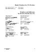
Handy Numbers for U.S. Dealers Epson Customer Resource Center Epson Faxback System Epson Bulletin Board System (800) 922-8911 (310) 782-4214 (310) 782-4531 Numbers and Addresses for Dealers Outside the U.S. Epson Canada, Ltd. 95 Mural Street Richmond Hill, Ontario LAB 3G3 ;htp (800) GO-EPSON .. (416) 881-5765 Epson Latin America, Inc. 6100 Blue Lagoon Drive Floor 2, Suite 220 Miami FL 33126 (305) 265-0092 Phone: Fax: (305) 265-0097 Epson Do Brazil Av.
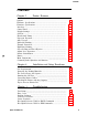
Contents Contents Chapter 1 - Printer Features Options ................................................................................. 1-3 1-3 Hardware Specifications ........................................................................... 1-12 Firmware Specifications ......................................................................... 1-13 Interfaces ................................................................................................ 1-17 Control Panel ............................
Contents Chapter 4 Disassembly and Assembly 4-1 4-1 4-2 4-3 4-4 4-5 4-6 4-7 4-8 4-9 Precautions ............................................................................................. Tools ....................................................................................................... Service Checks After Repair .................................................................. Screw Specifications ...............................................................................
Printer Features Chapter 1 Printer Features Options.. .................................................................................................... Hardware Specifications.. ......................................................................... Printing Method ............................................................................... P a p e r H a n d ......... l i n g ....................................................................... Precautions for Paper Handling ....................
Printer Features C094 MAIN Board Assembly (Main Control Board) ................. C094 PNL Board Assembly (Control Panel Circuit Board) ................... C076 PSB Board Assembly (Power Supply Circuit Board) .................. Printer Mechanism ........................................................................ Housing Assembly ......................................................................... Commonly Asked Questions and Answers ............................................
Printer Features Table 1-14. Optional Interface ........................................................... Table 1-15. Identifying Errors Using the LEDs ................................ Table 1-16. Group 1 Features ............................................................ Table 1-17. Group 2 Features (ESC/P Mode) ..................................... Table 1-18. Group 2 Features (IBM Mode) ........................................ Table 1-19. Group 3 Features (Power-on Settings) ........................
Printer Features 1 The FX-870/1170 combines advanced firmware, reliability, and affordability in a single light-weight unit.
Printer Features 80-column model 136-column model Figure 1-1.
Printer Features options C814011 Single-bin cut-sheet feeder (80-column) Single-bin cut-sheet feeder (136-column) High-capacity cut-sheet feeder (80-column) High-capacity cut-sheet feeder (136-column) Tractor unit (80-column) Tractor unit (136-column) Front sheet guide (80-column) Front sheet guide (136-column) C823051 C823071 C823101 C823141 C823151 Serial I/F card (Type B) 32KB intelligent serial I/F card (Type B) 32KB intelligent parallel I/F card (Type B) Coax interface (Type B) Twinax interface (T
Printer Features 9 x 7 matrix (high-speed draft) Dot matrix: 9 x 9 matrix (drafk) 18 x 23 matrix (NLQ) Paper Handling Feeding methods: Friction feed (front/top) Push tractor feed (front/rear) pull tractor feed (front/rear/bottom) Push-pull tractor feed (front/rear) Method to use for Fanfold: Cut sheets: Envelopes: Labels: Rdk Line spacing: each type of paper: Tractor feed Friction feed Friction feed Tractor feed Friction feed l/6”, L/B”, or programmable (l/216”, minimum) Table l-l.
Printer Features Precautions for Handling Paper Friction feed l Set the release lever to the FRICTION position. l Load the paper from the front or top entrance. l Do not use continuous paper. l Do not perform any reverse paper feeds within the top 0.34” (8.5 mm) area and bottom 0.88” (22 mm) area. l Do not perform reverse feeds greater than l/6” after the paper end has been detected. l Use the paper-tension unit. l Insert multi-part cut-sheet forms only from the front.
Printer Features Paper Specifications See Tables 1-2, 1-3, 1-4, 1-5, 1-6, and 1-7. Normal Environmental Conditions Recycled paper, envelopes, and labels require normal environmental conditions, which are the following: Temperature: Humidity: 59-68”F(15-25°C) 30 - 60 % RI-I Table 1-2. Specifications for Cut Sheets (Standard Paper) Width top insertion front insertion Length Thickness Weight Quality 5.8-l 0.1” (148-257 mm) 80-column 136~column 5.8-l 6.5” (148-420 mm) 7.2-10.
Printer Features Table 1-4. Specifications for Continuous Paper Width 4- 10” (101-254 mm) 80-column 4-l 6” (101-406 mm) 136~column 0.0025-0.012” (0.065-0.32 mm) 14-22 lb (45-70 kg) (52.3-82 g/m*) - single sheet 12-l 5 lb (34-50 kg) (40-58.2 g/m*) - each Standard or carbonless duplicating paper Recycled paper (at normal temperature and humidity levels) 4 sheets (1 original + 3 copies) maximum Thickness Weight Quality Copies Table 1-5. Specifications for Envelopes Size No. 6 No.
Printer Features Table 1-7. Specifications for Roll Paper Size Thickness Weight Quality Note: - 8.5 f 0.12” (216 A 3 mm) 0.0028-0.0035” (0.07-0.09 mm) 14-22 lb (45-70 kg) (52.3-82 g/m*) Standard paper Roll paper is available optionally only for the 80-column model, and its diameter must not exceed 5” (127 mm). Printable Area Cut sheets top insertion 5.8-10.1” 5.8-16.5” fkont insertion 7.2-10.1” 7.2-14.
Printer Features Continuous paper 101-254 mm (4-10"): 80 columns 101-406 mm (4-16"): 136 columns > *1 Printable Area >L+ 0 0 0 0 0 0 0 G c c 0 3 0 0 0
Printer Features -_ Roll paper (80-column model only) top insertion 216 2 3 mm (8.5 2 0.12”) Printable Area WXYZ t -, WXYZ J - Figure 1-5. Printable Area for Roll Paper *I 0.12” (3.0 mm) or more Note: Paper feed accuracy cannot be assured within 24 mm (0.94”) from the bottom edge of the paper (top insertion only).
Printer Features Electrical Specifications See Table l-8. Table 1-8. Electrical Specifications for 120 V Model Rated voltage Input voltage range Rated frequency range Input frequency range Rated current Power consumption . Dielectric strength 120 VAC 103.5132 VAC 50-60 Hz 49560.5 Hz 1.8 A Approx. 45 W ( 80 columns) Approx. 45 W (136 columns) (Self-test in draft mode, 10 cpi) 1.2K VAC rms, 1 second (Between AC line and chassis) Environmental Conditions Table 1-9.
Printer Features Safety Approvals Safety standards RF1 * UL1950 with D3 CSA!z2.2#220 FCC class B Firmware Specifications Print Control Printing direction Text mode Bidirectional printing with logic seeking. (Unidirectional printing can be specified by software.
Printer Features Table 1-12. Print Speed Type of letters High-speed draft Draft pica Draft elite Condensed draft pica Emphasized draft pica NLQ normal pica 380 285 342 243 142 57 Print speed [cps] 11421 (320) ii421 [1701 v221 1711 Notes: 1. The printing speed for high-speed drafl is reduced to the value in ‘I( )” with thick paper (over 0.007 inches or 0.18 mm). 2. The printing speed for high-speed draft is reduced to the value of “draft pica” when any graphic character is in the line. 3.
Printer Features I BUSY ACKNLG . . . . . . . . . . . . . . . . -.- D A T A p STROBE t1 t,: 0.5 p-s (minimum) t2: 7 w (approximate) 5: 5 w (approximate) t1 t1 t2 t3 Figure 1-6. Data Transmission Timing Table 1-13. Connector Pin Assignments and Signal Functions Signal Return Pin Pin No. No. Signal Name Dir.
Printer Features Table 1-13. Connector Pin Assignments and Signal Functions (Cont.) signal Return Pin Pin Signal No. No. Name 12 30 PE 13 14 15 16 17 18 9 to 30 31 - Dir. Out - - AUTO FEED In XT NC -0V CHASSIS GND - 32 - 33 34 35 - 36 - NC GND im In ERROR Out GND NC -- - SLCT IN In Description A HIGH signal indicates that the printer is out of paper. . Pulled up to +5 V through a 3.3K-ohm resistor.
Printer Features should be shielded and connected to the chassis of the host computer and the printer, respectively. 4. All interface conditions are based on TTL level. Both the rise and fall times of each signal must be less than 0.2 us. 5. Data transfers must not be carried out by ignoring the ACKNLG or BUSY signal. (Data transfers to this printer can be carried out only after confirming the ACKNLG signal or when the level of the BUSY signal is LOW.
Printer Features Control Panel READY ,, OPL,, Figure 1-7. Control Panel Buttons OPERATE PAUSE/TEAR OFF PAPER FEED IFONT - 1 lock type button (non-lock push-type buttons) 3 LEDs Indicators READY - (green) FONT (Draft, Roman, Sans serif) - (green) CONDENSED - (green) Buttons PAUSE l When there is data in the input buffer: Selects printing or pause alternately.
Printer Features FONT (ALT) - Selects NLQ Roman, NLQ Sans serif, Draft, and condensed ofthose 3 fonts in rotation: (DraR + Sam serif * Dra f t cond. 3 Sam cond. + Roman + Draft + Roman cond. 3 Draft cond. . ...) (The factory setting is Draft, uncondensed font.) The selection is executed when the button is released and is stored in non-volatile memory. Micro Feed Function l l When paper is in the paper path: 1. Press the PAUSE button to stop printing. 2.
Printer Features Bin Selection for the Cut Sheet Feeder l When there is no paper in the paper path: Holding down the FONT (ALT) button while pressing PAUSE or PAPER FEED alternates bin selection if a double-bin cut-sheet feeder is attached and friction feed is selected. Paper Ejection Holding down the FONT (ALT) button and pressing PAPER FEED ejects a cut-sheet forward or feeds continuous paper backward to the paper park position.
Printer Features Default Settings -. You can set certain default parameters to be used at printer initialization. To change the parameters shown in Table l-16, Group 1 Features, follow the steps below: 1. Turn on the printer while pressing the FONT button. The printer beeps once and prints the current default settings on the paper loaded in the paper path. 2. Press FONT to select a parameter. The FONT and CONDENSED LEDs turn on, off, or blink to show the current parameter selected.
Printer Features To change the settings shown in Table 1-17, Group 2 Features (ESC/P mode), or in Table l-18, Group 2 Features (7BM mode), follow the steps below: 1. Turn on the printer while pressing the FONT and PAUSE buttons. The printer beeps once and prints the current character table for either ESC/P or IBM mode on the paper loaded in the paper path. 2. Press the FONT button to select the character table. The FONT, CONDENSED, and BEADY LEDs turn on, off, or blink to show your selection.
Printer Features Table l-18. Group 2 Features (IBM Mode) FONT COND. READY LED L E D LED OFF OFF ON OFF OFF BLINKS OFF ON OFF [ OFF 1 ON 1 ON Character Table Character table PC437 (table 1) (standard) PC437 (table 2) PC865 (table 1) PC865 (table 2) Notes: 1. For table 1, codes 80-9FH are control codes. (ESC 7 is set.) For table 2, codes 80-9FH are printable characters. (ESC 6 is set.) 2. The character tables for ESC/P mode and IBM mode aresaved independently in non-volatile memory.
Printer Features sheet feeder (CSF), the first sheet is used for scaling the sheet length. Then, the maximum number of printable lines is printed in the bottom line of the sheet and saved in non-volatile memory as the default page length. Page lengths are saved individually when a dual-bin CSF is in use.
Printer Features Paper-out Detection If the paper-out sensor detects a paper out, the printer automatically enters a pause condition after feeding or printing several lines. When a paper-out is detected, load new paper properly and set the printer ready to print by pressing the PAUSE button.
Printer Features position. If a paper out is detected before printing starts, the sheet is loaded automatically to the top-of-form position, without PAPER FEED being pressed. l Continuous paper loading and ejection (paper park) Move the release lever to REAR PUSH/FRONT PUSH position and load paper into the tractor unit. Press PAPER FEED to load the paper automatically to the top-ofform position.
Printer Features Printer Initialization The printer is initialized in the following cases. l l When the printer is turned on. When the INIT signal or CMREQ (optional I/F ) is input. When the printer is initialized, it performs the following functions: l The printhead returns to the leftmost position (carriage home). l The READY LED lights. l The printer clears the print buffer and input data buffer. l The line spacing is set to l/6 inch.
Printer Features Buzzer The buzzer beeps for 0.1 second at a time. These beep sounds are combined in various ways, as shown below, to indicate different meanings. In the following table, each ” l ” stands for one beep. Table 1-21. Buzzer Functions Description Sounds when a BEL code is received. A carriage error has occurred. (Indicators blink sequentially in the clockwise direction.) =atal error (Indicators blink simultaneously.) No beeps. - RAM ncorrect memory m w a y 0.ae.0ao.
Printer Features Main Components The components of the FX-870/1170 are designed for easy removal and replacement during maintenance and repair. The main components are: l l l l l C094 MAIN board assembly C094 PNL board assembly C076 PSB board assembly Printer mechanism Housing assembly The following figure shows the main components of the FX-870/1170. Platen Gap Adjust Lever Release Lever B Board Assembly IN Board Assembly Pril iter Mechanism Figure 1-11.
Printer Features C094 MAIN Board Assembly (Main Control Circuit Board) Basically, the same board layout is used in both the 136~column model and the 80column model. The CPU on this board controls all the main functions of the printer. It consists of a TMP90C041F 8-bit CPU, an E05A55YA gate array, an E2PROM, a PSRAM, a MASK ROM, motor drivers, and head drive transistors. PF MOTOR DRIVER ,,DAld-lfil-l CPU TM,p,), CTRr”.
Printer Features C094 PNL Board Assembly (Control Panel Circuit Board) This boardis the control panel ofthe F’X-870/1170, consisting of a power button, three function buttons, and three indicator LEDs. Figure 1-13. CO94 PNL Board Assembly (Control Panel Circuit Board) CO76 PSB Board Assembly (Power Supply Circuit Board) This board is composed of an input filter circuit, a transforming circuit, a switching regulator circuit, a rectifying circuit, a smoothing circuit, and various protecting circuits.
Printer Features Printer Mechanism The printer mechanism consists of a g-pin impact dot head, a carriage mechanism, a carriage motor, a paper feed mechanism, a paper feed motor, a ribbon feed mechanism, and various sensors. 136-column model 80-column model Figure l-16.
Printer Feature8 Housing Assembly The printer mechanism and all the boards are contained in a housing assembly that consists of the upper case and the lower case. Figure 1-16.
Printer Features Commonly Asked Questions and Answers This section contains facts that customers often want to know about this printer. The question-and-answer format is to make it easier for you to scan through the information. 1. Q. What are the FX-870 and FX-1170 printers? A. The FX-870 and FX-1170 printers are the direct replacements for the FX-850 and FX-1050 printers. 2. Q. What is the rated print speed for the FX-870 and the FX 1170? A.
Printer Features 7. Q. Do the FX-870 and FX-1170 use the same ribbons as the FX-850 and FX- 1050? A. Yes. 8750 (fabric) for the FX-870 8755 (fabric) for the FX-1170 8758 ribbon only replacement pack (Never use ribbons for 24-pin printers. To extend printhead life, use only the Epson ribbons listed above.) 8. Q. What is the part number for the printhead? A. F031000 If any of the pins in the printhead are shorted, be sure to replace the main board at the same time as the printhead. Q.
Printer Features 13. Q. How many paper paths are there for the FX-870 and FX-1170? A. The printers have 4 paper paths: Top feed Bottom feed Rear feed Front feed 14. Q. How is the tractor used for feeding with the FX-870/1170? A. The FX-870 and FX-1170 come with one tractor, which can be positioned for three different types of feeding: Front feed push tractor Rear feed push tractor Top-mounted pull tractor 15. Q. How many sheets of multi-part paper can the FX-870/1170 handle? A.
Installation and Setup Chapter 2 Installation and Setup Procedures Site Requirements .................................................................................... Removing the Packing Materials ............................................................. The Correct Power On Sequence .............................................................. Running the Self-Test .............................................................................. Connecting Printer Cables ...........................
Installation and Setup Procedures 2 This chapter provides tips to help you select a site, set up, and test the printer. There is information on the using the parallel and serial interfaces, along with cabling configurations for serial transmission. The last portion of the chapter provides information customers need to know about this printer to ensure maximum problem-free operation. Site Requirements . Selection of a suitable location is essential to proper operation of the FX-870/1170.
Installation and Setup Running the Self-Test The self-test checks the printer mechanically and electronically to make sure it works properly. If the printer runs the self-test successfully, it means that everything is operational in the printer (with the possible exception of the interface circuit). To run the self-test, hold down the PAPER PEED button while turning on the printer. You can use any paper path and any acceptable paper type to run the self-test.
Installation and Setup The cable configuration for connecting the printer serially to a 25-pin (XT-type) computer connector is shown in the figure below. 25pin to 25pin Serial Cable PtiIltff side 1 FGND, Computer ,l FGND :~.-x,xl 5 CTS 4 ,5 CTS 6 DSR 4 +6 DSR Figure 2-2. Serial Cable Configuration to a 25Pin Computer Connector - Checking the Printer with the Computer The paragraphs below describe ways to check the computer’s connection to the printer.
Installation and Setup Then try sending a print screen again or type: DIR > PRN and press Enter at the MS-DOS prompt to print a listing of the current directory. (If you needed to change the MS-DOS MODE command to reroute the computer’s output to the correct port, edit the system’s AUTOEXEC.BAT file to include this MODE command automatically.
Troubleshooting Chapter 3 Troubleshooting Test Points ................................................................................................ Error Codes ............................................................................................... Problem Isolation ..................................................................................... Serial Communications Errors ........................................................ Connector Locations .........................................
Troubleshooting 3 The information in this section can help you identify causes of printer problems and test the printer to isolate the part that needs to be replaced. The chapter also contains illustrations showing connector locations and sensor locations. Once you have read this chapter to determine what tests you need to run on the printer, see Chapter 4 for instructions on how to disassemble the printer.
Troubleshooting Table 3-2. Sensor Test Points Test Method (Set Meter to Ohms. Check with Printer Power Off.) Sensor Connector Number Release Lever (CN4) Platen Gap (CW CR Home (CN7) Front PE (CN3) Place one lead on each pin. Change the release Meter should toggle between lever position. open and short. Place one lead on each pin. Change the adjust lever position. Meter should toggle between open and short. Place one lead on each pin. Move carriage to and away from home position.
Troubleshooting [TERMINAL ASSIGNMENT] Ho #8 0 #I7 0 #6 0 #I5 0. #4 0 #3 0 #2 0 #’ 0 Note: The printhead is upside down in this illustration. [WIRE ASSIGNMENT] Note: 1 The commons correspond to the following printhead dot wires: J COM. 2 = #2, #4, #6 COM. 8 = #7, #8, #9 COM. 14=#1,#3,#5 Figure 3-1. Printhead Resistance Table 3-4.
Troubleshooting Table 3-5. Printhead Driver Test Points - Test Method (Set Meter to Diodes. Check with Printer Power Off.) Transistor Numbers Q2, Q4, Q5 Q6, Q8, Q9 Ql 0, Ql 1, Q12 Emitter and base are marked on the CO94 MAIN board. Check from base to collector, from base to emitter, and from emitter to collector. Reverse leads and test again. Q3, Q7, Q13 Meter Reading Consistent readings for all transistors, within YZ 20%. Not open and not shorted between base and collector and base and emitter.
Troubleshooting Error Codes Table 3-7. Error Codes Error Warning Cause Error 3uzzer beeps: moo.0 Carriage error Use flowchart 2 in this chapter to isolate the problem. 3uzzer beeps: Y.0.0.. Memory error RAM abnormality. 3uzzer beeps: Memory error E2PROM abnormality. Paper out error l mnnnn 3uzzer beeps: moooooOenoeonnn l l l Buzzer beeps: Paper out error m l l l Continuous paper has run out. There is no cut sheet paper in the CSF. No paper was present at the start of a self-test.
Troubleshooting Problem Isolation Most printer problems can be corrected by replacing the defective unit. First, identify the problem from the symptoms you observe using the table below. Then, follow the instructions in the corresponding flowchartto correct the problem. Table 3-8. Symptoms and Flowchart References Possible Problems . Symptom Printer dead, or abnormal operation at power on. Carriage does not move, or carriage operation abnormal. l l l l l l l Self-test printout has poor quality.
Troubleshooting Table 3-8. Symptoms and Flowchart References (Continued) Symptom Flowchart or Solution Possible Problems When I try to load paper, the printer feeds it back out. The printer continues printing beyond the paper end onto the platen. After I micro adjust top margin, the top margin of subsequent pages is wrong or drifts down the page. The carriage slams into the right side of the printer, or the printer doesn’t find home after power on. The FX-1170 will print only BO columns.
Troubleshooting Table 3-9. IdentiQing Serial Communications Errors (Continued) Problem Device timeout error Characters are printed as graphics or are printed in italics. l l Possible Cause Solution The computer is not set for infinite retries to the printer. Type a MODE command from the MS-DOS prompt that includes the infinite retry parameter.
Troubleshooting Chart 1. Printer Dead at Power On 0 START Use correct AC v o l t a g e . (No fluctuation from AC range shown at left is permitted. NO I I board. No No Measure the VP I (+35 (+35 V) V) at at pin oin 10 10 I of CM2 on the C076 PSR board assembly. Dower on, does the new “;e;c;dhe board assembly. 1 No Disconnect CM14 and check the power supply * voltages out of circuit a t A pin 10 and pin 1.
Troubleshooting Chart 1. Printer Dead at Power On (Continued) Disconnect connector CM1 2 and power on printer. Yes initialize? R;g;y;N;ha board. 1 END Check motors and printhead. (If shorted, use Tables 3-5 and 3-6 to check drivers on C994 MAIN board, and if bad, replace main board at same time. 1 I ” board.
Troubleshooting Chart 2. Carriage Does Not Move or Moves Abnormally on the CO94 U&IN kcuro t h r connmtors. Manually wow the Check the gears. timing belt. and belt pulley for war, brmkagr, and Coralgn objects. Replace parts and lubrlcatr as nerdad. (km Chapter 5.1 Rapl8ca the Cg94 MAIN board. Repl8ce CR motor. I f any coil Is shorted. use Table 3-6 to test CR drivers on the CW4 WIN board. and I f b a d . replaca rln board at SW tlr.
Troubleshooting Chart 3. Paper Does Not Feed or Feeds Abnormally n START YOS TY*s / No / \No IR, il roslstanca o f tha PF motor. I s I t 63 l /- 3 IN o Replace P F motor. I f my coil Is shortrd. use Table 3-6 to Cast PF drlvors on the CW4 WIN board. and If bad. raplace uln board at aaa tin.
Troubleshooting Chart 4. Poor Print Quality in Self-Test and turning on the prlntar. Are Q Srcurs t h e connectors. bo8rd connected any dots lsslng or drrgglng? q 1 for bent or No Perform thll Chmck printhead rrslstance. I f It Is not 16.5 ohms +/- 1.6 olmr raplax t h r prlnthrad. I f a n y prlnthmd pin I s shortrd. use Tablo 3-5 t o chack drlwrs QZ - Q13 o n tha uln bawd, and I f shorted. raplace at t h e sm tlm 8s the printhead.
Troubleshooting Chart 5. Ribbon Not Feeding Properly Q START Rap I ace the ribbon mark. rlght and l e f t , does ribbon 3-14 See Figure 6-21 (page 6-18). Check gearing for broken or wore gears or foreign objects stuck In the gears. Repface eny gears necessmy. Lubricate as necessary. (See Chapter 5.1 And make sure gears are turning smoothly.
Troubleshooting Chart 6. Data fhm Host is Printed Incorrectly - Run self-tart. (Turn on prlntor *hIlo holding down the PAPER FEED button. 1 I f self-tart I s g8rbl.d. t h 8 problr I s with the RDN or C194 RAIN bo8rd. Chrck daf8UltS shown in the self-test. Are they correct for the 8ppliC8tlOn? If not. sat th8m c o r r e c t l y . (Sm Def8Ult Settings I n Chaptar 1.1 E x i t progrv 8nd send 8 p r i n t scrmn from thm US-DOS prompt. R8pl8ca t h 8 C194 RAIN bo8rd. Chock softw8re conflgurrtlon.
Troubleshooting Chart 7. Page Length/Margins Incorrect Run self-test and chSck t h e p r i n t e r ’ s drf8ult s e t t i n g s 8gainst the settings In your 8pplic8t l o n SOftW8rS. printer. f-l Th8 problv Is wlth th8 softw8ro YOS The C894 IL&IN bo8rd “y bs b8d. (This I s mor8 r8rS than problems with softw8rS settings.
Troubleshooting Chart 8. Printout Double-Spaced the printer Is OK. At the MS-DOS prompt, type the following: NODE=LPTn:.6.P and press Enter. (“n” is the port you 8r* using. 1 Send another print screen. Disconnmt the cable. At the prlntar connector. you will see that the pin nmbers are Iabolod. P u t a piace o f tape over p i n 14 to block thr sIgnal f r a the p r i n t e r .
Troubleshooting Connector Locations The layout diagram below shows the positions of connectors on the C094 MAIN board. ‘R\\ / II’ PE Rear’ Figure 3-2.
Troubleshooting Sensor Locations The illustrations below show the locations of sensors in the printer mechanism. Figure 3-3. Release Sensor Figure 3-4.
Troubleshooting Printer Mechanism Figure 3-5. Platen Gap Sensor Rear Paper Guide Assembly Figure 3-6.
Troubleshooting Hex Quick Reference Table for ESC/P Commands Use the table below as an aid to read printer hex dumps. This table is for quick reference only. The user’s guide contains a detailed description of the control codes. Table 3-10. Hex. Codes for ESC/P Commands Hex. Dec.
Troubleshooting Table 3-10. Hex. Codes for ESC/P Commands (Continued) Hex. Dec.
Troubleshooting Hex Quick Reference Table for IBM Commands Use the table below as an aid to read printer hex dumps. This table is for quick reference only. The user’s guide contains a detailed description of the control codes. Table 3-11. Hex. Codes for IBM Commands Hex. Dec.
Troubleshooting Table 3-11. Hex. Codes for IBM Commands (Continued) I Hex. Dec.
Disassembly and Assembly Chapter 4 Disassembly and Assembly 4-1 Precautions ............................................................................................. 4-1 Tools ........................................................................................................ Service Checks After Repair ................................................................... 4-2 4-3 Screw Specifications ...............................................................................
Disassembly and Assembly 4-13 4-14 4-14 4-15 4-16 4-17 4-18 4-18 4-19 4-20 4-21 4-22 4-22 4-23 4-24 4-24 Figure 4-12. Removing the PF Motor Assembly ................................. Figure 4-13. Disassembling the PF Gear Train .................................. Figure 4-14. Positioning the Release Lever for Insertion ................... Figure 4-15. Removing the Carriage Guide Assembly ....................... Figure 4-16. Attaching the Timing Belt.. ..............................................
Disassembly and Assembly 4 This section provides information you need to know to disassemble or assemble the printer. Precautions Read the precautions below before you disassemble or assemble the printer. WARNING Before disassembling, assembling, or adjusting the printer, disconnect the power supply cable from the AC power outlet. Failure to do so may cause physical injury. The power switch is wired in the secondary circuitry.
Disassembly and Assembly Service Checks After Repair -- Before you send the printer back to the customer, fill in the checklist in Table 4-3 to note the current state of the components. This checklist facilitates servicing and shipping. Table 4-3.
Disassembly and Assembly Screw Specifications This chapter uses abbreviations for small parts, such as screws and washers. Tables 4-4 and 45 list these abbreviations. Table 4-4. Abbreviations Used for Screws Abbreviation Part Name CBB Cross-recessed Bind head B tight screw CBC CBN Cross-recessed Bind head C tight screw Cross-recessed Bind head N tight screw . CBS Cross-recessed Bind head S tight screw Table 4-5. Screw Types and Abbreviations Head Washer (assembled) Body Side TOP .
Disassembly and Assembly Notes for Unit Removal and Installation This section describes the procedures for disassembling and assembling the main components of the printer. Generally, you can install a component in the printer simply by reversing the procedure for removing the component. Therefore, this chapter does not describe assembly procedures in most cases. If necessary, special notes on assembling or adjusting a component are given at the end of the description of each procedure.
Disassembly and Assembly Items to Remove Before Disassembling the Printer 1. Remove the paper guide assembly, ribbon, top cover, front cover, paper eject cover, and tractor unit. Figure 4-2. Removing the Paper Guide Assembly Note: Remove the paper eject cover and the tractor unit by pushing and releasing the hooks at both sides. When remounting them, be sure to snap these hooks on the projecting parts.
Disassembly and Assembly Removing the Panel Unit - 1. Remove the paper guide assembly, ribbon, top cover, f?ont cover, paper eject cover and tractor 2.’ 3. unit. fSee page 4-5.) Push the two clips on the bottom of the panel unit and remove the panel unit. Remove the flexible flat cable (FFC). -, Figure 4-3. Removing the Panel Unit Assembly Note The FFC cable must be connected properly, as shown below. Plain Face 1 FFC Cable / Face with exposed terminals at the 5 end of the cable. Figure 4-4.
Disassembly and Assembly Removing the Printhead 1. 2. 3. Remove the paper guide assembly, ribbon, top cover, front cover, paper eject cover, and tractor unit. (See page 4-5.) Remove the two CBS (M3x8) screws from the printhead, lift the printhead up, and remove the FFC cable. Remove the printhead. FFC Figure 4-5.
Disassembly and Assembly Removing the Upper Housing Assembly 1. 2. 3. 4 5 -_ Remove the paper guide assembly, ribbon, top cover, front cover, paper eject cover, and tractor unit. (See page 4-5.) Remove the panel unit. (See page 4-6.) Remove the four CBC (M4x15) screws securing the upper housing assembly. (There are only three screws in the 80-column printer.) Use a small screwdriver to push the two hooks through the cutouts, located on the front cover, to disengage the hooks from the plates.
Disassembly and Assembly Removing the Printer Mechanism 1. 2. 3. 4. 5. 6. 7. Remove the paper guide assembly, ribbon, top cover, front cover, paper eject cover, and tractor unit. (See page 4-5.) Remove the panel unit. (See page 4-6.) Remove the upper housing assembly. (See page 4-8.) Remove the four CBB (M4x12) screws securing the printer mechanism. Remove the CBS (M3x6) screw securing the interface cover.
Disassembly and Assembly Removing the Platen Assembly -_ 1. Remove the paper guide assembly, ribbon, top cover, front cover, paper eject cover and tractor unit. (See page 4-5.) 2. Remove the panel unit. (See page 4-6.) Remove the upper housing assembly. (See page 4-8.) Remove the two CBS (M3x8) screws securing the platen cover. Disengage the teeth of the platen shaft holders and rotate them. Then slide the left platen sh& holder to the left. Remove the platen knob.
Disassembly and Assembly Removing the Rear Frame Assembly 1. 2. 3. 4. 5. 6. 7. 8. 9. Remove the paper guide assembly, ribbon, top cover, front cover, paper eject cover, and tractor unit. (See page 4-5.) Remove the panel unit. (See page 4-6.) Remove the upper housing assembly. (See page 4-8.) Remove the printer mechanism. (See page 4-9.) Remove the platen assembly. (See page 4-10.
Disassembly and Assembly Removing the CR Motor Assembly 1. Remove the paper guide assembly, ribbon, top cover, front cover, paper eject cover, and tractor unit. (See page 4-5.) Remove the panel unit. (See page 4-6.) Remove the upper housing assembly. (See page 4-8.) Remove the face screw (M3x7) securing the CR motor assembly. After releasing the tension spring, disengage the timing belt from the CR motor assembly and hang it on the hook. Disconnect connector CN13 on the C094 MAIN board assembly.
Disassembly and Assembty Removing the PF Motor Assembly 1. 2. 3. 4. 5. 6. 7. Remove the paper guide assembly, ribbon, top cover, front cover, paper eject cover, and tractor unit. (See page 4-5.) Remove the panel unit. (See page 4-6.) Remove the upper housing assembly. (See page 4-8.) Remove the printer mechanism. (See page 4-9.) Set the release lever to the vertical or forward position. Remove the FFC cables and then the two CBS(M3x8) screws securing the PF motor assembly. Remove the PF motor assembly.
Disassembly and Assembly Disassembling the PF Gear Train 1. Remove the paper guide assembly, top cover, front cover, paper eject cover, and tractor unit. (See page 4-5.) Remove the panel unit. (See page 4-6.) Remove the upper housing assembly. (See page 48.) Remove the printer mechanism. (See page 4-Q.) Remove the CR motor assembly. (See page 4-12.) Remove the PF motor assembly. (See page 4-13.
Disassembly and Assembly Removing the Carriage Assembly 1. Remove the paper guide assembly, ribbon, top cover, front cover, paper eject cover, and tractor unit, (See page 4-5.) 2. Remove the panel unit. (See page 4-6.) 3. Remove the printhead. (See page 4-7.) 4. Remove the upper housing assembly. (See page 4-8.) 5. Remove the printer mechanism. (See page 4-9.) 6. Remove the platen assembly. (See page 4-10.) 7. Remove the left frame of the printer mechanism. (See page 4-11.) 8.
Disassembly and Assembly Assembly Note When attaching the timing belt to the carriage assembly, secure the timing belt using the 1eR and right clips of the carriage assembly as shown below. Make sure there is no slack in the timing belt. ‘- Clip Timing Figure 4-16.
Disassembly and Assembly Removing the Ribbon Drive (RD) Assembly 1. Remove the paper guide assembly, ribbon, top cover, front cover, paper eject cover, and tractor unit. (See page 4-5.) 2. Remove the panel unit. (See page 4-6.) 3. Remove the upper housing assembly. (See page 4-8.) 4. Remove the printer mechanism. (See page 4-9.) 5. Remove the platen assembly. (See page 4-10.) 6. Remove the left frame of the printer mechanism. (See page 4-11.) 7. Disengage the timing belt from the CR motor assembly.
Disassembly and Assembly Removing the Home Position (HP) Sensor 1. 2. 3. Remove the paper guide assembly, ribbon, top cover, front cover, paper eject cover, and tractor unit. (See page 4-5.) Remove the clip of the HP sensor. Remove the sensor. Disconnect the HP lead from the HP sensor. - Figure 4-18. Removing the HP Sensor Removing the Platen Gap (PG) Sensor 1. 2. 3. 4. 5. 6. -, Remove the paper guide assembly, ribbon, top cover, front cover, paper eject cover, and tractor unit. (See page 4-5.
Disassembly and Assembly Removing the Front and Rear Paper End (PE) Sensors 1. 2. 3. 4. 5. 6. 7. 8. Remove the paper guide assembly, ribbon, top cover, front cover, paper eject cover, and tractor unit. (See page 4-5.) Remove the panel unit. (See page 4-6.) Remove the upper housing assembly. (See page 4-8.) Remove the printer mechanism. (See page 4-9.) Remove the platen assembly. (See page 4-10.) Remove the rear frame assembly. (See page 4-11.
Disassembly and Assembly Removing the Release Sensor 1. 2. 3. 4. 5. 6. 7. 8. Remove the paper guide assembly, ribbon, top cover, front cover, paper eject cover, and tractor unit. (See page 4-5.) Remove the panel unit. (See page 4-6.) Remove the upper housing assembly. (See page 4-8.) Remove the printer mechanism. (See page 4-9.) Remove the platen assembly. (See page 4-10.) Remove the rear frame assembly. (See page 4-11.) Remove the two clips for the release sensor mounted on the rear paper guide assembly.
Disassembly and Assembly Arranging the Cables When you assemble the printer, arrange the cables as shown in Figure 4-22. El Printer Mechanism (Bottom) - W Figure 4-22.
Disassembly and Assembly Disassembling the Tractor Unit 1. Remove the paper guide assembly, ribbon, top cover, front cover, paper eject cover, and tractor unit. (See page 4-5.) 2. Release the two clips for cog (17) from the tractor shaft. Remove the cog. 3. Remove the right tractor frame from the tractor shaft and the tractor guide shaft. 4. Remove the E-ring from the tractor shaft. 5. Remove the right tractor, the paper support unit, and the left tractor from the tractor shaft and tractor guide shaft.
Disassembly and Assembly Removing the C094 MAIN Board Assembly 1. 2. 3. 4. 5. 6. 7. 8. 9. Remove the paper guide assembly, ribbon, top cover, front cover, paper eject cover, and tractor unit. (See page 4-5.) Remove the panel unit. (See page 4-6.) Remove the upper housing assembly. (See page 4-8.) Remove the printer mechanism. (See page 4-9.) Disconnect the cable from connector CN2 on the C076 PSB board assembly. Remove I/F’ support from the C094 MAIN board assembly.
Disassembly and Assembly Removing the C076 PSB Board Assembly NOTE To remove the C076 PSB board assembly for replacement, you must use a special extractor tool, available from Epson Parts Order Services. After obtaining the special tool shown, follow the procedure below. I OneWai (Rivet Head) Screw Figure 4-26. Special Extractor Tool WARNING Do not touch the heat sink attached to the FET (Ql) when the printer is powered on. If you touch the heat sink, you may suffer from electric shock. 1. 2. 3. 4. 5.
Disassembly and Assembly CBC (M3X8) CBB (M3X12) C076 PSB BoardAssembly Figure 4-27.
Adjustments, Maintenance, and Lubrication Chapter 5 Adjustments, Maintenance, and Lubrication Adjusting the Printer Mechanism ............................................................ Platen Gap Adjustment ................................................................... Bidirectional Alignment Adjustment ....................................................... Overview of the Bidirectional Alignment Adjustment.. .................. Bidirectional Alignment Adjustment Procedure .........................
Adjustments, Maintenance, and Lubrication 5 Adjusting the Printer Mechanism This section describes the various adjustments required to keep the printer mechanism in optimum condition. Platen Gap Adjustment If you have changed the printhead, rotated or reassembled the carriage guide shaft, moved the parallelism adjustment bushing, or if printing is abnormal or ribbon tension is loose, you must adjust the gap between the platen and the printhead. 1. 2. 3. Remove the printer mechanism from the lower case.
Adjustments, Maintenance, and Lubrication Left Frame 8ox Oriver -4/ ’ Adjustment Bushing Figure 5-2. Parallelism Acijustment Bushing 9. Rotate the adjusting bushing until the platen gap is large enough for a 0.36 mm thickness gauge, but too narrow for a 0.40 mm thickness gauge. 0.38 mm +I Id Figure 5-3. Platen Gap 10. Move the carriage until the edge of the printhead is at the 75th column print position for an 80-column printer or at the 130th column print position for a 136-column printer. 11.
Adjustments, Maintenance, and Lubriition Bidirectional Alignment Adjustment This section describes how to adjust the bidirectional print position to ensure correct printing. Overview of the Bidirectional Alignment Adjustment The FX-870/1170 prints characters when the carriage moves from both from left to right and from right to left. Therefore, the printing in one direction must be correctly aligned with the printing in the other direction. Otherwise, printed vertical lines may be staggered.
Adjustments, Maintenance, and Lubrication Adjustment Operation 1. - Turn on the printer’s power while pressing the PAUSE, PAPER FEED, and FONT buttons simultaneously. The printer enters draft mode and prints the current adjustment value and four lines of the H character. (See Figure 5-3.) If the vertical lines are well aligned, go to step 4. Otherwise, go to step 3. Referring to the odd-numbered lines (1st and 3rd), adjust the even-numbered lines (2nd and 4th).
Adjustments, Maintenance, and Lubrication Preventive Maintenance No preventive maintenance is required other than occasionally vacuuming the printer mechanism to remove dust and paper debris and regularly cleaning the case exterior with denatured alcohol. After cleaning the unit, check that it is properly lubricated as described under Lubrication, below. Also inspect the springs and rollers to see that they are operating properly.
Adjustments, Maintenance, and Lubrication Table 5-2. Lubrication Points Ref. No. Lubricant G-26 3 Platen gap adjustment slots on the left frame (excluding the two slots at the bottom) The arms and tab of the RD assembly d The shaft end of the drive roller assembly 4 The ribbon drive gear train G-26 5 The oil pad in the carriage assembly o-2 6 The cam surface of the tractor clutch cam G-26 7 The cam end of spur gear 34.
Principles of Operation Chapter 6 Principles of Operation Printer Mechanism Operation ................................................................. Printhead Mechanism ...................................................................... Carriage Mechanism ........................................................................ Platen Gap Adjustment ................................................................... Paper Handling Mechanisms ..........................................................
Principles of Operation Figure 6-8. Push-pull Tractor Operation Using the Rear Paper Entrance ........................................................ Figure 6-9. Push-pull Tractor Operation Using the Front Paper Entrance ....................................................... Figure 6-10. Release Lever .................................................................... Figure 6-11. Release Lever Setting Functions ...................................... Figure 6-12.
Principles of Operation Table 6-6. Table 6-7. Table 6-8. Carriage Motor Drive Modes ............................................. 6-27 Repairing the C076 PSB Board Assembly ........................ 6-31 Repairing the C094 MAIN Board Assembly .................... .
Principles of Operation 6 This chapter explains the mechanical and electrical operations of the FX-870/1170. At the end of the chapter, there are tables for component-level diagnosis of the main logic board and the power supply board. Printer Mechanism Operation This section describes the FX-870/1170 printer mechanism and explains how the printer works. The FX-870/1170 printer mechanism features a 9-pin impact dot printhead for serial printing.
Principles of Operation 4. As soon as the current through the coil is switched off, the force induced in the coil rod stops. The plate then returns to its original position (the position assumed before the coil was energized) through the action of the plate spring. After the dot wire hits the platen, the rebounding force of hitting the platen works with the wire resetting spring to pull the wire back to its original position.
Principles of Operation Carriage Mechanism The timing belt is connected to the lower side of the carriage. With the printhead installed, the carriage moves in either direction along the carriage guide shaft. The carriage (CR) motor, a stepping motor, drives the timing belt, which moves the carriage. The home position (HP) sensor detects the home position of the carriage. Timing Belt Pulley I CR Motor Figure 6-2.
Principles of Operation Platen Gap Adjustment The platen gap (the gap between the platen and the printhead) can be adjusted to allow the printer to use paper of different weights or thicknesses. When the platen gap adjust lever is moved forward or backward, the carriage guide shaft rotates. This rotation moves the carriage either toward or away from the platen, and changes the platen gap.
Principles of Operation Paper Handling Mechanisms During normal operation, paper is fed to the printer, advanced to the specified position, and ejected from the printer. These paper handling operations are performed by various paper handling mechanisms, such as the tractors, platens, rollers, and gears. This section describes the printer’s paper handling mechanisms. Paper Feed Mechanisms Cut sheets are fed by friction. Continuous paper is fed by a tractor.
Principles of Operation Paper Advance Mechanisms This section describes how the friction advance and tractor advance mechanisms work to advance the paper through the printer. Friction Advance Method The paper is held between the platen and paper guide rollers and between the paper tension roller and paper tension unit cover. The paper feed (PF) motor pinion gear, turning in the direction of the black arrow, drives the paper advance reduction gear.
Principles of Operation Push Tractor Method When the push tractor method is used with the rear entrance, the torque generated by the PF motor is transmitted to the push tractor gear through the PF motor pinion gear, paper advance reduction gear, and tractor reduction gear. When the PF motor pinion gear turns in the direction of the black arrow, the tractor gear rotates in the direction of the black arrow and thus feeds the paper into the printer.
Pthcipk of Operation - Paper (Continuous) Paper Tension Roller Paper Tension Roller Gear / Platen Gear PF Motor P&h Tractor ‘Push Tractor Gear Figure 6-6.
Principles of Operation Pull Tractor Method The pull tractor advances paper in basically the same way as the push tractor. The push tractor is installed at the paper entrance and pushes the paper into the printer mechanism. The pull tractor, however, is installed at the paper exit and pulls the paper out of the printer mechanism. As the result, the paper tension unit is not required. Figure 6-7 illustrates pull tractor operation when the paper is fed through the bottom paper entrance.
Principles of Operation Push-pull Tractor Method The push-pull tractor method is a combination of the push and pull tractor methods. Two tractors are used to advance the paper: one at the front paper entrance and the other at the rear paper entrance. They operate simultaneously to push and pull the paper through the printer mechanism. Figure 6-8 illustrates push-pull tractor operation when the paper is fed through the rear paper entrance.
Principles of Operation I Paper Drive Roller / \ ctor Reduction Gear PF Motor Pinion Gear PF Motor \ PaDer Advance Reduction Gear l . \ - l . \’ Platen Gear \ Paper Drive Roller Gear ush Tractor Gear Push Tractor Figure 6-9.
Principles of Operation The Release Lever The release lever is used to select friction or tractor feeding or to release the paper. When the release lever is set to the friction feed position, the paper guide rollers are pressed against the platen. When it is set to one of the tractor feed positions, this pressure is released and the paper guide rollers are separated from the platen.
Principles of Operation Paper Paths This section describes the various paths the paper follows through the printer mechanism. These paper paths are divided into four groups, depending on the entrance the paper is fed from (top, rear, bottom, or front). Note: The front paper-end (PE) sensor is located in front of the printer mechanism and the rear PE sensor is located behind the printer mechanism. Top Entrance Figure 6-12 shows the paper path for friction feeding using the top entrance.
Prlnclples of Operatbn Rear Entrance Figures 6-13 and 6-14 show the paper paths for tractor feeding using the rear entrance. The rear entrance can be used for any of the following paper feed methods: push tractor feed, pull tractor feed, or the push-pull tractor feed. When the rear entrance is used, the rear PE sensor senses when paper is out. Paper (Continuous) Paper Tension Roller Prlnth Pap& Guide Rollers Figure 6-13.
Principles of Operation Paper (Continuous) \ Printhead Paper Guide Rollers Figure 6-15. Paper Path for Push-pull Tractor Feeding Using the Rear Entrance Bottom Entrance Figure 6-16 shows the paper path for tractor feeding using the bottom entrance. The bottom entrance is used only for pull tractor feeding. When the bottom entrance is used, the front PE sensor senses when paper is out. Paper (Continuous) Tractor Paper Front PE Sensor \ Lower Paper Guide Roller Figure 6-16.
Principles of Operation Front Entrance - Figures 6-17 through 6-20 show the paper paths for the front entrance. The front entrance can be used with any of the following paper feed methods: friction feed, push tractor feed, pull tractor feed, or push-pull tractor feed. When the front entrance is used, the front PE sensor senses when paper is out. Paper (Continuous), Paper Tension Roller Paper Front PE Sensor \ Lower Paper Guide Roller -_ Figure 6-17.
Principles of Operation Paper (Continuous) Front PE Sensor \ Lower Paper Guide Roller Figure 6-19. Paper Path for Pull Tractor Feeding Using the Front Entrance Paper Drive Roller Tower Paper Guide Roller Front PE Sensor Push Tractor - Figure 6-20.
Principles of Operation Ribbon Advance Mechanism The ribbon is held between the ribbon advance roller (ribbon driving gear) and the ribbon pressure roller. When the carriage moves on the shaft, the timing belt turns the belt driven pulley, and the torque is transmitted to the ribbon driving gear through the gear train. The ribbon driving gear rotates counterclockwise no matter what direction the carriage moves, because the planetary gear is used in the gear linkage. Table 6-2.
Principles of Operation Power Supply Operation The FX-870/1170 printer is powered by a 120 VAC power supply board (C076 PSB board assembly). This board outputs the DC current necessary to drive the printer control circuits and the printer drive mechanism. Fuse Fl(2.5 A/125 V) is used to protect the power supply circuit of the board in case of a short circuit. Table 6-3. Power Supply Input Voltage and Fuse Rating Input Voltage 103.5 - 132 VAC Fuse Fl Rating 2.
Pfinciples of Operation The +5 VDC voltage-overload protection circuit cuts the +5 VDC line output ifthe voltage exceeds +7 VDC. It stops the operation of the switching circuit and then the output of +35 VDC voltage. The +35 VDC line has a voltage-overload protection circuit and a voltage drop protection circuit. The +35 VDC voltage-overload protection circuit cuts the +35 VDC line output if the voltage exceeds +36 VDC.
Principles of Operation Secondary - I I I i I I I t Full Wave Pectification - S m o o t h i n g - $M$ing . . Circuit Circuit a , Smoothing Circuit -9 +35 VDC +5v Switching Regulator .~~~-~~~~~-~~~~~ +5v Over Current Control Circuit ---------------+5v Filter Circuit 4 +5 V D C AC input _ Photo- + coupler \ I +35 V Line Detector Circuit +35 V Line Voltage Overload Protection Circuit L ZD51 +t I+ 2052 J - Voltage Drop Protection Circuit Power - Switch Figure 6-22.
Principles of Operation Control Circuit Operation The control circuit consists of two circuit boards: the CO94 MAIN (main control circuit board) and the CO94 PNL (control panel circuit board). This section describes the operation of these boards. Control Circuit Operation Overview The CPU on the CO94 MAIN is an 8-bit TMP9OCO41F microprocessor (9.83 MHz). It oversees control of all the components of the printer.
Principles of Operation Figure 6-24 shows the data flow from the host computer to the printhead. Data sent fkom the host computer is converted to image data and transmitted to the printhead through the gate array. CPU RAM I Host computer + Input buffer L I Image data transfer Gate Array (EOSABGYA) Figure 6-24.
Principles of Operation Table 6-5 lists the fimctiona of the main componente of the CO94 MAIN. Table 6-5. Functions of Main Components of CO94 MAIN IC or Circuit Functions TMP90C041 F (2Cl) Receives data from the host computer and loads it to the input buffer in RAM. Expands the input data held in the buffer to create image data. Loads the image data to the image buffer in RAM. Transfers the image datato the printhead drive circuit. Also controls various printer mechanism parts, such as the motors.
Principles of Operation Reset Circuit The control circuits are initialized when the RESET signal is issued. The reset operation occurs under these two conditions: 1. Power on reset Immediately after the power is turned on, +35 VDC is rapidly generated. Because it takes a moment for the voltage at ZD2 to reach +31.5 V, the voltage at the DISC terminal on the gate array does not reach +5 VDC until capacitor C24 is fully charged.
Principles of Operation Sensor Circuits The FX-8’70/1170 printer has the following sensors: CRHOME, PE (FRONT), PE (REAR), PG (platen gap), RELEASE LEVER(RL), and HEAD TEMPERATURE. All the sensors are mechanical switches, except the rear PE sensor, which is a photo diode, and the HEAD TEMPERATURE sensor, which is a thermistor. - In addition to the sensor circuits, a +35 V monitor circuit and a Vref circuit are also provided. The +35 V monitor circuit sets the pulse length of the head drive signal.
Principles of Operation Carriage Motor Drive Circuit The carriage motor drive circuit controls the CR motor. An open loop, constant-current drive arrangement runs the CRmotor. 2-2 and 1-2 phases are used to excite the motor. A 2-2 phase step is equivalent to a 1-2 phase step doubled. Table 6-6 describes the motor drive modes. The CR motor drive circuit of the SLA7024M (IC6) detects and regulates the amount of current flowing in the carriage motor coil.
Principles of Operation Paper Feed Motor Drive Circuit The PF motor, a stepping motor, advances the paper at a minimum advance rate of l/216 inch. This motor is a 2-2 phase, constant-voltage, drive motor. CPU ports (P70 tc P73) are used to control the PF motor. Phase data for the PF motor is output through these ports. PFA to PFB are turned on or off within the pPA1476H (ICl), depending on the phase data sent from the CPU.
Principles of Operation Printhead Drive Circuit The printhead drive circuit receives two types of signals: image data and the pulse length control signals. Image data is created in the CPU, transferred to the gate array, and latched to the printhead. The pulse length control signal is set by the CPU. The pulse length is adjusted referring to the voltage of the +35 V line. These two types of signals are sent to the printhead to print each dot. Figure 6-29 shows the printhead drive circuit.
Principles of Operation 2 E PROM Control Circuit Figure 6-31 shows the E2PROM control circuit. The E2PROM is non-volatile memory containing information, such as the top-of-form position. Because the E2PROM is a serial I/O device, the gate array converts the parallel data (sent fiorn the host computer) into serial data. B5A66YA (IC4) SCL SCK SDA SDA - CPU (IC2Cl) Data Bus Figure 6-31.
Principles of Operation Component Repair Information (for Dealers Outside the U.S.) This portion of the manual provides additional information for servicers outside the U.S. who need to make repairs to components on the circuit boards. (U.S. service technicians can ignore these pages.) Repairing the C076 PSB Board Assembly This section gives instructions for repairing the C076 PSB board assembly. It describes various problems, likely causes, checkpoints, and solutions.
Principles of Operation Table 6-7. Repairing the C076 PSB Board Assembly (Continued) Problem cause The voltage of the Q3, ICl, PCl, t35 V line is below PC2 or ZD51 is the specified value. bad. Q2 is bad. 6-32 Checkpoint Solution Check the voltage waveforms at Q3. Replace Q3, ICl, PCl, PC2 or zD51. Check the voltage waveforms at Q2. Replace Q2.
Principles of Operation Table 6-7. Repairing the C076 PSB Board Assembly (Continued) Checkpoint Solution Problem CalIS@ he +5 V line is ad. The +35 V line is bad. Check the +35 V line. Refer to the items described above. IC51 is bad. Check the oscillation waveform (IC51 pin 5) and the switching waveform (IC51 pin 8). Replace IC51. Q51 or Q52 is bad. Check the switching waveform at Q52 emitter. Replace Q51 or Q52.
Principles of Operation Repairing the C094 MAIN Board Assembly This section gives instructions for repairing the C094 MAIN board and describes various problems, symptoms, likely causes, checkpoints, and solutions. The checkpoint column shows proper waveforms, resistance values, and other information for each component of the C094 MAIN board. Table 6-8. Repairing- the C094 MAIN Board Assembly Problem Symptom The CPU 4bnormal weration at does not rower on. operate properly.
Principles of Operation Table 6-8. Repairing the C094 MAIN Board Assembly (Continued) Cause Checkpoint Solution The CPU Abnormal operation at does not operate power on. properly. The CPU is defective. Check the oscillator signal (IC2Cl pin 27 or pin 28). If the signal is not correct, replace IC2Cl. Otherwise, replace CRl. Carriage operation abnormal. IC6 is defective. Check the input signal (pin 5) and the output waveform (pin, 8). Replace IC6.
Principles of Operation Table 6-8. Repairing the C094 MAIN Board Assembly (Continued) - Problem Self-test printing abnormal Self-test printing abnormal. Symptom Cause Solution Check the head pulse signal at pin 31 (input) and pin 63 (output). Replace IC4. One of the Check the head drive signal at the base and head driie the emitter of each transistor. transistors is defective (QZ 4,5, 6, 8, 9, 10, 11, or 12). If the signal at the base is normal, replace the transistor. Otherwise, replace IC4.
Principles of Operation Table 6-8. Repairing the C094 MAIN Board Assembly (Continued) Problem Cause Symptom Paper feed abnormal. ICl is The printer does not feed defective. the paper at all or the paper feed is irregular. Incorrect printing of data sent from the host computer. Data is corrupted when the p a r a l l e interface is used. Epson FX-87011170 Either IC4 or IC5 is defective. Checkpoint Check the input signal (pin 2) and the output waveform (pin 3).
Reference Materials Chapter 7 Reference Materials Connector Summary ................................................................................. Circuit Diagrams ...................................................................................... Circuit Board Component Layouts ........................................................ Outline Drawings ................................................................................... 7-1 7-5 7-10 7-13 List of Figures Figure 7-1.
Reference Materials 7 Connector Summary Figure 7-1 illustrates the interconnection of the primary components. Table 7-1 summarizes the functions and sizes of the connectors. 7 AC IN 4 CO94 MAIN BOARD ASSEMBLY (1 1 CN4 t 1 CN6 1 CNl +iiq (CN2k 1 CN13 1 I CO76 PSB BOARD ASSEMBLY L I I PF MOTOR I ASSEMBLY PRINTER MECHANISM t + I I CO94 PNL BOARD ASSEMBLY I Figure 7-1.
Reference Materials Table 7-1.
Reference Materials See Table 1-14 for CNl (Centronics interface) signal functions and pin assignments. Table 7-3. CN3, Front PE Sensor (CO94 MAIN Hoard Assembly) Table 7-2. CN2, Optional I/F (CO64 MAIN Hoard Assembly) No.
Reference Materials Table 7-11. CN13, CarA& Motor (CO94 MAlN Board Assembly) Table 7-8. CNS, Printhead (CO94 MAIN Board Assembly) So. 1 2 3 4 5 6 7 8 9 10 11 12 13 14 l/O Signal Name 0 HD2 0 c246 0 HD6 0 HD8 0 HD4 0 HD9 TMP I 0 c789 0 TMP 0 HDl 0 HD3 0 HD5 0 HD7 0 Cl35 Function Head Data 2 Head Drive Common Head Data 6 Head Data 8 Head Data 4 Head Data 9 Head Temperature Head Drive Common Head Temperature Head Data 1 Head Data 3 Head Data 5 Head Data 7 Head Driie Common Table 7-9.
Reference Materials Circuit Diagrams B:,& sE:IOK I A /I/II/II III ,,,, I Il/IIl/II Head Conrrol IIIIII ’ 0,‘ OTC1132 II /IIm O,‘” Ill i - Pf Molar Control CNL LE
Reference Materials . I \ = - - - Figure 73.
Surge Current ProtectIon CB 220Op/lKV _ 3 TI P ‘-9; *, 051 FMP-G125 t5V DC Reourator ct-42 Clrcult PSC -I +35V/O.?A F LPZOl-2R5SO R RW R4 0 C 6 I I F , +SV/I.OA II o.3gs 0 3 O.,u,‘AC250V 16K F , FG Psc PO. 7 A R7 F , +5V/l.OA C58 O.Olu tection I I 1 I 7 c57 L7OOp/ IKV !Or _ 1 7 FG iV Over IZJI 2.
THI Bohm/25C CB 2200p/lKV C r T’ I _ 3’ CN2 PT-0’ PSC R5 = lOK/ 2w 01 AGOI Cl2 - L70pRKV _ 2. CSl 0 C6 II 4, I 0.1 u/ACZ%,V = F-G !, z%p (L2) 33ooun1 5ov C52 33oou 5ov It,I- a_ C 5 6 -- 22oop 1 KV 22”dP t- ‘-T iF G 1 c.57 A7oOp/ 1KV ELF160290M 1 ? FG I- -2O.Z2u/AC250V Fl 2.
Reference Materials GND 0 SW4 *OPERA , *PAPER FEED t&-----h “’ 0 *FONT CNI rPAUSE/l-OFF CONDENSED o7 *SW3 ij-L o6 SW2 0 5 LED3 N 4 FONT 0 1/1 N 0 LED2 I STATUS 2 L/I LED1 N 41 Note: The STATUS LED is not implemented in this model. Figure 7-6.
Reference Materials Circuit Board Component Layouts PF Motor PF Motor e.m Parallel hlterface /CNl PG Sensor c cN5\ Ett CN7 PE Rear/ %i \\ !z?Rm / PE Front I I EY P r Y i n t h e a d P&iead zeyi Drivers C N \ EN3”” 1 2 - CN2 Figure 7-7.
Reference Materials n EEm EPS-I I MODEL 1 Figure 7-8.
Reference Materials 6 I.202 lmal fi L2DJ CO94 PNL q SW3 pJ zLLD I cl----, -I I I cl : : Sw2 A S S Y 2 0 0 6 1 6 0 0 0 I I i 0 SWI FL+ 16 I A,--4 SW4 CMK- 54x1 Am Note: The STATUS LED is not implemented in this model. Figure 7-9.
Reference Mater& Outline Drawings r I --- I I I 380 ’ I I I i Figure 7-10.
Reference Materials I L I - I I z-- r- r-r-=- 0--1 Figure 7-11.
Index Symbols +35 V 3-1, 6-19, 6-25, 6-28, 6-29 line 6-31, 6-32 monitor circuit 6-26 detector 6-19 +5 V 3-1, 3-4, 6-19, 6-25, 6-28 line 6-33 136-column 1-10, 4-8, 5-2 80-column 1-8,4-8,5-2 A abbreviations 4-3 Abicomp 1-21 AC power 3-1, 4-1, 6-19 outlet 2-1, 6-31 source 6-20 accessories 1-34 ACKNLG 1-13 addresses vii adjust 4-1 lever 1-24, 3-2, 4-11, 5-1, 6-4 adjustment 3-6, 4-1, 5-1, 5-2, 5-3 bushing 4-11, 5-1, 5-2 airmail 1-7 alignment 5-3 ALT 1-18, 1-19 Amphenol 1-13 analog input port 6-22 assembly 4-1 t
Index blinking 1-19 bond paper 1-7 bottom entrance 6-9, 6-15 box driver 5-1 BRASCII 1-21 buffer 1-1, 1-13, 1-15, 1-17, 1-22, 1-24, 1-26, 6-24 full printing 1-24 bushing 5-1 BUSY 1-13, 6-29 /READY 3-8 buttons 1-17 buzzer 1-27, 3-6, 6-2 C C076 PSB board 1-28, 1-30, 4-23, 4-24, 6-19, 6-31, 6-32, 6-33 C094 MAIN board 1-28, 1-29, 3-6, 3-7, 3-18, 4-9, 4-23,6-22, 6-24, 6-34,6-35, 6-36, 6-37, 7-2, 7-5, 7-10 C094 PNL board 1-28, 1-30, 6-22, 7-9, 7-12 cable 1-13, 1-16, 2-1, 3-1, 3-6, 3-8, 4-1, 4-2 configuration 2-2
Index common 3-2, 3-3 communications errors 3-7, 3-8 component 1-28, 6-34 layouts 7-10 repair 6-31 condensed 1-12, 1-17, 1-18, 1-19 connector 1-14, 3-1, 3-3, 4-9, 4-12, 4-23, 4-24, 7-2 locations 3-18 summary 7-1 continuity 3-1, 3-4 continuous paper 1-1, 1-5, 1-9, 1-17,6-5 control circuit 6-22 codes 3-21 through 3-24 panel 1-17, 1-22, 1-23, 1-28, 1-30, 2-1, 6-19,6-22, 7-4, 7-9, 7-12 copier paper 1-7 copies 1-6 correction value 5-3 cps 1-13 CPU 1-29, 3-5, 6-22, 6-35 CR (carriage) home 1-26, 2-1, 3-2, 3-6, 3-
Index dot 6-1 wires 3-3 double-space 3-7, 3-17 draft 1-13, 1-18, 1-19,5-4 drive circuit 6-24, 6-27, 6-28,6-29 roller assembly 5-6 signals 6-1 voltage 6-1 driver 3-2, 3-4, 3-6 carriage motor 3-4 paper feed motor 3-4 printhead 3-4 selections 1-33 driving wires 6-1 dust 5-5 duty 1-24 cycle 1-11, 2-4 E ETROM 1-27, 2-1, 3-5, 3-7,5-3, 6-24 control circuit 6-30 ejection 1-24 electrical specifications 1-11 electromagnetic interference 2-1 elite 1-1, 1-12 emitter 3-4, 6-36 emulation 1-20 entrance, paper 6-6 throug
Index font 1-12, 1-17, 1-18, 1-19, 1-20, 1-21, 1-22, 5-4 form feed 1-24 frame 4-11 ground connector 2-2 left 4-11, 4-18 right 4-11 France 1-21 frequency range 1-11 friction 6-5, 6-6 feed 1-4, 1-5, 6-13, 6-16 mechanism 1-5 front cover 4-5 entrance 6-7, 6-8, 6-10, 6-11,6-16, 6-17 feed 1-35 insertion 1-8 PE sensor 1-24, 3-2, 3-20,4-19,6-13,6-15, 6-16, 6-26, 7-3 sheet guide 1-3 full wave rectification 6-19 fuse F1 6-19 rating 6-19 FX-850/1050 1-1, 1-33 FX-86e/286e 1-1, 1-33 G gap 1-25, 3-2, 3-6, 4-18, 5-1, 5-
Index pulse signal 6-36 temperature 6-26 thermistor 1-19,3-5 heat 6-2 sink 4-24,6-31 hex dumps 1-23,3-21, 3-23 codes 3-21 through 3-24 high capacity cut-sheet feeder 1-3 duty printing 1-24 speed draft 1-1, 1-13 voltage error 1-19,3-5 home position 1-26,2-1,3-2,3-6,3-7,3-19,4-18,6-3,6-4,6-26,7-3 sensor 1-26,3-2, 3-6,3-7,3-19, 4-18, 6-26, 7-3 hooks 4-5, 4-8 horizontal tab 1-26 host 3-6, 3-15 housing assembly 1-28 HP (home position) sensor 1-26, 3-2, 3-6, 3-7, 3-19, 4-18, 6-26, 7-3 humidity 1-6, 1-7, 1-11 I
Index italic 1-21, 3-8 Italy 1-21 L labels 1-4, 1-5, 1-6 layout 1-29 diagram 3-18, 7-10 LEDs 1-19, 2-1 left frame 4-11, 4-18 length 1-6 lever adjust 1-24, 3-2,4-11, 5-1, 6-4 release 1-5, 1-24, 1-27, 3-2, 3-5, 4-13, 4-14, 5-1, 6-6, 6-7,6-12,6-26 life 1-33 line spacing 1-4, 1-26 lines 1-23 load paper 3-7 loading 1-24 position 1-18, 1-27 logic level 1-13 low voltage 1-19,3-5 lubricants 4-1 lubrication 5-1, 5-5 points 5-7 M main board 1-28, 1-29, 3-6, 3-7, 3-18, 4-9, 4-23, 6-22,6-24,6-34,6-35,6-36,6-37 circuit
Index N NLQ 1-13, 1-18, 1-19, 5-4 noise 1-15, 6-19 non-volatile memory 1-18, 1-20, 1-22, 1-23, 1-26, 6-30 null modem cable 2-2 O ohms 3-2, 3-3 oil 5-5 pad 5-6 open 3-2, 3-4 OPERATE 1-17, 3-1 operating modes 1-33 optional I/F 1-16,7-3 boards 1-1, 1-3, 3-7,3-8,4-23 oscillation waveform 6-33 oscillator 6-35 oscilloscope 4-1 outlet 2-1, 6-31 outline drawings 7-13, 7-14 output voltages 6-19 outside the U.S.
Index tension roller 6-6, 6-7 gear 6-6 unit 1-5,6-9 thickness 1-25 width 1-8 parallel 1-34, 3-6 cable 2-2 interface 1-3, 1-13, 2-1, 6-29 parallelism adjustment bushing 3-6, 4-11, 5-1, 5-2,5-3 parameters 1-22 parity 2-4, 3-7 Parts Order Services 4-24 path l-l, 6-13, 6-14, 6-15 PAUSE 1-17, 1-18, 1-19, 1-21, 1-22, 1-24, 5-4 /TEAR OFF 1-17 PE (paper end) 1-24,3-2,3-20,4-19,6-13,6-15,6-16,6-26, 7-3 front rear 1-24,3-2,3-20,4-19,6-13,6-15,6-16,6-26, 7-3 sensor 1-24,3-2,3-7,3-20,4-19,6-13 through 6-16,6-26,7-3,7-
Index consumption 1-11 on 1-22, 3-6, 3-7, 3-9, 3-10, 6-34 default settings 1-13, 1-22 hours 1-11 reset 6-25 sequence 2-1 outlet 2-1,6-31 supply 1-28, 1-30, 3-1, 3-4, 4-1, 4-4, 4-23, 4-24, 6-19, 6-31 through 6-33, 7-4 voltage 3-5, 3-6 precautions 4-1 preventive maintenance 5-5 primary circuit 3-1, 4-1, 4-4, 6-20, 6-31 print buffer 1-1, 1-13, 1-15, 1-17, 1-22, 1-24, 1-26, 6-24 control 1-12 quality 3-13 screen 2-3, 2-4 speed 1-13, 1-33 printable area 1-8 characters 1-22 printer cables 1-13,1-15,2-1 through 2-
Index.
Index schematics 7-5 through 7-9 screwdriver 4-1 screws 4-3 secondary circuit 2-1, 3-1, 4-1, 4-4, 6-20 self-test 1-22, 2-1, 3-6, 6-36 sensor 1-31, 3-1, 3-2, 3-6, 3-7, 4-18, 4-19, 4-20, 6-3, 6-19 circuits 6-26 front PE 1-24, 3-2, 3-20, 4-19, 6-13, 6-15, 6-16, 6-26, 7-3 HP 1-26, 3-2, 3-6, 3-7, 3-19, 4-18, 6-3, 6-26, 7-3 locations 3-19 rear PE 1-24, 3-2, 3-20, 4-19, 6-13, 6-14, 6-26, 7-4 release 3-19, 4-20, 7-3 serial 1-16, 3-7, 7-3 cable 2-2 communications errors 3-7, 3-8 I/F card 1-1, 1-3, 3-7, 3-8, 4-23 se
Index T tear-off 1-17, 1-18, 1-19, 1-20, 1-24, 1-27 temperature 1-6, 1-7, 1-11, 2-1, 6-2, 6-26 tension spring 4-12 test pins 3-2 points 3-1 through 3-4 tests 3-1 text mode 1-12 thermal protection 1-24 thermistor 2-4, 3-3, 3-5, 6-2, 6-26 thick paper 1-4, 1-5 thickness 1-6, 1-7, 1-8, 1-25, 4-1,6-4 gauge 4-1,5-2 thin paper 1-4 timeout 2-4, 3-8 timers 2-1 timing 1-14, 5-3 belt 4-12, 4-15, 4-16, 6-3, 6-18 tools 4-1 top cover 4-5 entrance 6-6, 6-13 insertion 1-8 margin 3-7 -of-form 1-17, 1-24 tractor 6-5, 6-6 cl
Index voltage 1-19, 1-24, 3-1, 3-5, 3-6 change 6-2 detector 6-19 drop protection circuit 6-20 error 1-19, 1-27, 3-5 input 6-19 monitor circuit 6-26 output 6-19 overload protection circuit 6-20 range 1-11 supply 6-19 volts 3-1 Vref circuit 6-26 W wall switches 2-1 WARNING 4-1, 4-4, 4-24, 3-1 washers 4-3 waveform 6-31, 6-32, 6-33, 6-34, 6-37 weight 1-6, 1-7, 1-8, 2-1, 6-4 width 1-6, 1-7, 1-9 wire 6-1 resetting spring 6-2 wires 1-3 word length 3-8 X XON/XOFF 3-8 Z Zero face 1-20 Index-14 Epson FX-870/1170