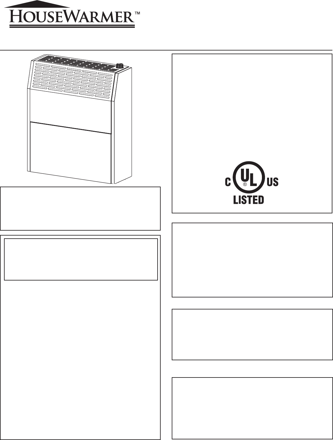
INSTALLATION INSTRUCTIONS AND OWNER'S MANUAL DIRECT VENT WALL FURNACE STANDARD MODELS: HWDV080DV(N,P)-1 HWDV181DV(N,P)-1 MODELS WITH BLOWER: HWDV080BDV(N,P)-1 HWDV181BDV(N,P)-1 GAS-FIRED Installer: Leave this manual with the appliance. Consumer: Retain this manual for future reference. WARNING: If the information in these instructions are not followed exactly, a fire or explosion may result causing property damage, personal injury or loss of life.
TABLE OF CONTENTS SECTION PAGE Included in the Box .................................................................................................. 3 Hardware Packets .................................................................................................... 4 Tools Needed ............................................................................................................. 4 Gas Specifications ...............................................................................................
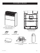
INCLUDED IN THE BOX DIRECT VENT HEATER (INSIDE WALL MOUNTING PLATE ATTACHED ON BACK) HEATER HARDWARE PACKET VENT SHIELD 24632-0-0508 INSTALLATION TEMPLATE (TEMPLATE FOR HWDV080 ON REVERSE SIDE) VENT KIT HARDWARE PACKET OUTSIDE WALL MOUNTING PLATE & VENT CAP INLET & OUTLET TUBES Page 3
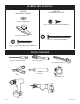
HARDWARE PACKETS VENT KIT HARDWARE PACKET HEATER HARDWARE PACKET NYLON WASHER (2) #10 X ½” PHILLIPS HEX HEAD SCREW (3) PLASTIC TOGGLE (6) #10 X 2 ½” HEX HEAD SCREW (4) #10 X 1 ½” SLOTTED HEX HEAD SCREW (6) TOOLS NEEDED PHILLIPS SCREW DRIVER SNIPS 5/16 NUT DRIVER ADJUSTABLE WRENCH CAULKING TAPE MEASURE SAW DRILL Page 4 24632-0-0508
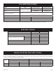
GAS SPECIFICATIONS MODEL FUEL HW080 MAXIMUM INPUT MINIMUM INPUT 8,000 Btu/hr Propane/LP -- Natural gas HW181 MANIFOLD PRESSURE 5,000 Btu/hr 9,000 Btu/hr NAT 18,000 Btu/hr 9,500 Btu/hr LP Natural gas: 4" water column pressure Propane/LP gas: 10.0" water column pressure 3/8" MINIMUM PRESSURE MAXIMUM PRESSURE 5" W.C.P. 10.5" W.C.P. 11" W.C.P. 13" W.C.P.
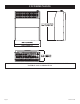
UNIT DIMENSIONS MAKE SURE THAT APPLIANCE IS SUITABLE FOR THE GAS SUPPLY AVAILABLE: NATURAL GAS OR PROPANE/LP.
IMPORTANT SAFETY INFORMATION Children and adults should be alerted to the hazards of high surface temperatures and should stay away to avoid burns or clothing ignition. Any safety screen or guard removed for servicing must be replaced prior to operating the heater. Do not use this heater if it has been under water. Immediately call a qualified service technician to inspect the heater and to replace any part of the control system and any gas control which has been under water.
SAFETY INFORMATION FOR USERS OF LP-GAS Propane (LP-Gas) is a flammable gas which can cause fires and explosions. In its natural state, propane is odorless and colorless. You may not know all the following safety precautions which can protect both you and your family from an accident. Read them carefully now, then review them point by point with the members of your household. Someday when there may not be a minute to lose, everyone's safety will depend on knowing exactly what to do.
INTRODUCTION Always consult your local Building Department regarding regulations, codes or ordinances which apply to the installation of a direct vent wall furnace. Instructions to Installer 1. Installer must leave instruction manual with owner after installation. 2. Installer must have owner fill out and mail warranty card supplied with furnace. 3. Installer should show owner how to start and operate furnace and thermostat. Warning: Any change to this furnace or its control can be dangerous.
REQUIREMENTS FOR MASSACHUSETTS For all side wall horizontally vented gas fueled equipment installed in every dwelling, building or structure used in whole or in part for residential purposes, including those owned or operated by the Commonwealth and where the side wall exhaust vent termination is less than seven (7) feet above finished grade in the area of the venting, including but not limited to decks and porches, the following requirements shall be satisfied: 1. INSTALLATION OF CARBON MONOXIDE DETECTORS.
TERMINATION CLEARANCES A B C D E F G H I J Description Clearance above grade, veranda, porch, deck, or balcony Clearance to window or door that may be open Clearance to permanently closed window Vertical clearance to ventilated soffit located above the terminal within a horizontal distance of 2 feet (610 mm) from the center line of the terminal Clearance to unventilated soffit Clearance to outside corner Clearance to inside corner Clearance to each side of center line extended above meter/regulator assem
GAS SUPPLY Locating Gas Supply The gas line can enter the unit either through the floor or outside wall. The gas line opening should be made at this time. Location of the opening will be determined by the position of floor joists and the valve and union used for servicing. Recommended Gas Pipe Diameter Pipe Length Schedule 40 Pipe Tubing, Type L Inside Diameter Outside Diameter Nat. L.P. Nat. L.P. 0-10 feet 1/2” 3/8” 1/2” 3/8” 0-3 meters 12.7 mm 9.5 mm 12.7 mm 9.
GAS SUPPLY (continued) Pressure Testing of the Gas Supply System 1. To check the inlet pressure to the gas valve, a 1/8" (3 mm) N.P.T. plugged tapping, accessible for test gauge connection, must be placed immediately upstream of the gas supply connection to the appliance. 2. The appliance and its individual shutoff valve must be disconnected from the gas supply piping system during any pressure testing of that system at test pressures in excess of 1/2 psig (3.5 kPa). 3.
INSTALLATION INSTRUCTIONS OVERVIEW Location - All Models Select a location near the center of the space to be heated. Overflow heat will circulate through doorways into adjacent rooms. The furnace is to be located on an outside wall. Locate wall studs so that wall opening will be located between wall studs. One wall stud can be used for attachment of inside wall plate. The wall opening required as shown in Figure 3 is a minimum diameter of 6 1/4" (159 mm).
INSTALLATION AND ASSEMBLY WARNING: Any change to this heater or its control can be dangerous. Provide adequate clearances and accessibility for purposes of servicing and proper operation. A manufactured home (USA only) installation must conform with the Manufactured Home Construction and Safety Standard, Title 24 CFR, Part 3280 or, when such standard is not applicable, the Standard for Manufactured Home Installations, ANSI Z225.1. Due to high surface temperature, keep children, clothing, and furniture away.
INSTALLATION AND ASSEMBLY 2 SILICON-BASED SEALANT MOUNTING PLATE CAP FLUE OUTLET TUBE AIR INLET TUBE Failure to position these parts in accordance with diagram or failure to use only parts specifically approved with these appliances may result in property damage or personal injury. INSTALLATION OF HOUSEWARMER PRODUCT INSTALLATION AND ANY REPAIRS TO THIS APPLIANCE MUST BE DONE BY A QUALIFIED SERVICE PERSON.
INTERIOR PREPARATION AND INSTALLATION OF THE BACK OF THE UNIT 1 Before installing unit, remove wall mounting plate from back of unit. 2 MOUNTING TEMPLATE FOR Locate the wall mounting plate template included in your kit and remove the perforated sections. Use painters tape to secure the wall mounting plate template onto the interior wall where the heater will be located. (Template for HWDV080 will be on the opposite side of the shown template.
INTERIOR PREPARATION AND INSTALLATION OF THE BACK OF THE UNIT 4 Housewarmer recommends the use of the wall template to properly cut the wall holes and place the heater. If the template is damaged or not included, refer to the table and graphic below for proper alignment of the wall holes and heater.. Be sure the baseboard does not get in the way.
INTERIOR PREPARATION AND INSTALLATION OF THE BACK OF THE UNIT 6 Pilot Hole Drill a pilot hole inside of the traced circle so that a jigsaw can be used to cut the holes out. 7 Use a jigsaw to cut the holes out of the wall and discard the inner circle debris. The wall is now prepared for the installation of the unit. 8 Pivot and remove casing door. Remove two screws from the back inside of the unit and detach the wall mounting plate from outside back of the unit.
INTERIOR INSTALLATION OF THE FRONT OF THE UNIT 1 Line up the two (2) tabs on the top of the wall mounting plate with the holes in the back of the unit. Slide the back of the unit onto the tabs of the wall mounting plate. 2 Secure the back of the unit into place using two (2) screws. Replace casing door. 3 GAS LINE After the back of the unit is attached to the wall, bring in the gas line as shown on page 18, or follow the installation template indications.
CUTTING THE VENT TUBES NOTE: Flue outlet tube and air inlet tube should be measured and cut to the proper length from the back of the unit to the outside wall of the house. See page 22, boxes 3 and 4. IMPORTANT: The appliance’s venting system should be inspected at least once a year and immediately cleaned if necessary. 1 FLUE OUTLET TUBE AIR INLET TUBE MOUNTING PLATE CAP LONG SCREWS (4X) SCREWS (3X) 2 4 1/2” to 12” THICK WALL This unit is to be installed on wall from 4 1/2" to 12" (114.3 mm to 304.
CUTTING THE VENT TUBES With the furnace installed on wall the 5" (127 mm) diameter air inlet tube and 3" (76 mm) diameter flue outlet tube are to be marked and cut using the following procedure. After cutting the tubes, each tube should be individually checked for proper length before installing by fitting in place. 3 Attach 5" (127 mm) diameter air inlet tube onto the collar of air drop assembly.
EXTERIOR INSTALLATION OF THE VENTING NOTE: Flue outlet tube and air inlet tube should be measured and cut to the proper length from the back of the unit to the outside wall of the house. There should be little to no venting showing on the outside of the house. 1 Place caulking (not provided) beneath the edge of the outside wall mounting plate. Use additional caulking to correct uneven wall surface, such as clapboard. 2 Attach 5" (127 mm) diameter air inlet tube onto the collar of air drop assembly.
EXTERIOR INSTALLATION OF THE VENTING 4 If installing onto vinyl, aluminum, or any type of siding that may warp or discolor, attach vent shield using two of the screws that attach the outside wall mounting plate. 5 3” DIA. VENT CAP COLLAR FURNACE CEMENT Apply furnace cement (not provided) to 3" (76 mm) diameter flue outlet collar on combustion chamber and to 3" (76 mm) diameter collar on vent cap.
EXTERIOR INSTALLATION OF THE VENTING 7 (3) #10 x ½” SCREWS Attach vent cap into the 3" (76 mm) diameter flue outlet tube. Attach vent cap to outside wall mounting plate with (3) #10 x 1/2" (13 mm) screws provided. 8 Installation of this Housewarmer product is complete.
REASSEMBLY AND RESEALING VENT-AIR INTAKE SYSTEM When vent-air intake system is removed for servicing the furnace, the following steps will assure proper reassembly and resealing of the vent-air intake assembly. 1 Remove old furnace cement from flue outlet collar on combustion chamber and collar of vent cap. Remove old furnace cement from both ends of 3" (76 mm) diameter flue outlet tube. 2 Remove old caulking beneath the edge of the outside wall mounting plate.
REASSEMBLY AND RESEALING VENT-AIR INTAKE SYSTEM 4 If installing onto a vinyl sided exterior wall, attach vinyl siding vent shield using two of the screws that attach the outside wall plate. 5 3” DIA. VENT CAP COLLAR FURNACE CEMENT Apply furnace cement to 3" (76 mm) diameter flue outlet collar on combustion chamber and to 3" (76 mm) diameter collar on vent cap. 6 FLUE OUTLET TUBE COLLAR OF FLUE OUTLET Attach 3" (76 mm) diameter flue outlet tube onto flue outlet collar on combustion chamber.
REASSEMBLY AND RESEALING VENT-AIR INTAKE SYSTEM 7 (3) #10 x ½” SCREWS Attach vent cap into the 3" (76 mm) diameter flue outlet tube. Attach vent cap to outside wall mounting plate with (3) #10 x 1/2" (13 mm) screws provided. 8 Reassembly and resealing vent-air intake system is completed.
INSTALLATION OF OPTIONAL BLOWER KIT HW125SCB 1 Remove front panel of heater by opening, then lifting one side out then the other. 2 Disconnect the power cord from the blower assembly. 3 Remove ground screw from blower mounting bracket.
INSTALLATION OF OPTIONAL BLOWER KIT HW125SCB 4 Insert blower into bottom of heater and attach with four (4) screws (provided). 5 Insert power cord through the hole in the bottom of the heater.
INSTALLATION OF OPTIONAL BLOWER KIT HW125SCB 6 Reconnect power cord to blower assembly. 7 Attach ground wires from the blower and power cord to the blower mounting bracket. 8 Slide fan control into the tabs on the right side of the chamber support.
INSTALLATION OF OPTIONAL BLOWER KIT HW125SCB 9 STRAIN RELIEF Pull blower cord from bottom to remove any excess wire from inside of the heater and attach strain relief to the cord on the underside of the heater. Insert strain relief into hole in the bottom of the heater. 10 Plug power cord into wall receptacle and reattach front panel of heater to complete installation. For replacement parts see Parts List on pages 42 and 43 and Parts View on page 44.
BEFORE OPERATING APPLIANCE WARNING Improper installation, adjustments, alterations, service or maintenance can cause property damage, personal injury or loss of life. Installation and service must be conducted by a Qualified Service Person. Under no circumstances should these heaters be modified. In case of gas leaks, close gas valve and call your Qualified Service Person. ATTENTION INSTALLER: INSTRUCT YOUR CUSTOMER ABOUT THE CORRECT OPERATION OF THE APPLIANCE BEFORE YOU LEAVE.
BEFORE OPERATING APPLIANCE 1 Do not use gases other than those indicated on the heater’s rating plate label. 2 Due to high temperature, the appliances should be located out of traffic and away from furniture and draperies. 3 Do not place clothing or other flammable material on or near the appliance. Do not dry clothes over heater. Blockage of hot air outlet will cause overheating of appliance, and possible fire. 4 Do not spray any aerosol near heater when in operation.
BEFORE OPERATING APPLIANCE 5 Do not touch grill while operating. Avoid burning yourself. 6 Avoid blocking air inlet and hot air outlet. 7 Do not place flammable elements on or near the heater. IMPORTANT: Under no circumstances should this appliance be modified. Do not operate this appliance if any parts have been removed for service.
BEFORE OPERATING APPLIANCE 8 WHAT TO DO IF YOU SMELL GAS • Do not try to light any appliance. • Do not touch any electrical switch; do not use any phone in your building. • Immediately call your gas supplier from a neighbor’s phone. Follow the gas supplier’s instructions. • If you cannot reach your gas supplier, call the fire department. • If you smell gas, shut off control valve, open doors and windows, and do not use any electrical device. Call our technical department at (877) 459-1583.
OPERATING INSTRUCTIONS FOR YOUR SAFETY READ BEFORE LIGHTING WARNING: Improper installation, adjustment, alteration, service or maintenance can cause property damage, personal injury, or loss of life. Installation and service must be performed by a qualified installer, service agency or the gas supplier. Keep burner and control compartment clean. A) This appliance has a pilot which must be lighted by hand. When lighting the pilot, follow these instructions exactly.
LIGHTING INSTRUCTIONS 1. 2. 3. 4. 5. 6. 7. 8. 9. STOP! Read the safety information on pages 36 and 37. Set the thermostat (gas control knob) to lowest setting. Turn off all electric power to the appliance (if applicable). Push in gas control knob slightly and turn clockwise to "OFF." Do not force. Wait ten (10) minutes to clear out any gas. Then smell for gas, including near floor. If you smell gas, STOP! Follow "B" in the safety information on page 37. If you do not smell gas, go to the next step.
PILOT FLAME CHARACTERISTICS 1 MAIN BURNER BURNER CHANNEL PILOT FLAME The pilot flame is blue and goes toward the main burner and thermocouple horizontally. A slight yellow tip on the flame is normal. The pilot flame must surround and extend approximately 1/4" (6 mm) beyond the thermocouple, and must extend beyond the first row toward the second row of main burner ports. THERMOCOUPLE MAIN BURNER FLAME CHARACTERISTICS 1 On the main burner, the burning gas forms a primary flame and a secondary flame.
MAINTENANCE INSTRUCTIONS WARNING: • Prior to any maintenance operation, it will be necessary to close the gas supply. • Only qualified personnel are allowed to operate these appliances without the front cabinet installed. OPERATION FREQUENCY External cleaning As required General cleaning of appliances As required. It is advisable to perform this operation annually. Gas leakage control Only if the equipment has been moved or if any gas circuit element has been changed.
TROUBLESHOOTING PROBLEM CAUSES SOLUTION Pilot flame does not light A) Gas supply valve closed B) Air in gas pipes C) Valve does not work properly A) Open gas supply valve B) Repeat ignition procedure C) Place knob on PILOT position and depress fully When ignition knob is released, pilot extinguishes A) Air remains in gas pipes B) Dirty pilot C) Thermocouple is defective A) Repeat ignition procedure B) Clean pilot C) Check with Service Department Burner burns abnormally A) Gas supply valve is not fu
PARTS LIST PLEASE NOTE: When ordering parts, it is very important that part number and description of part coincide. INDEX NO. 1 2 3 4 5 6 7 8 9 10 11 12 13 14 14 15 16 17 18 18 19 20 21 21 21 21 22 23 24 PART NO.
PARTS LIST PLEASE NOTE: When ordering parts, it is very important that part number and description of part coincide. INDEX NO. 25 26 27 28 29 30 30 31 32 32 33 34 34 35 36 37 38 39 40 41 NOT SHOWN NOT SHOWN NOT SHOWN NOT SHOWN NOT SHOWN NOT SHOWN NOT SHOWN NOT SHOWN PART NO.
PARTS VIEW 41 40 39 1 38 37 3 36 4 2 5 7 35 6 13 14 12 15 11 10 9 8 21 16 20 17 23 24 19 22 34 25 27 33 28 29 18 32 26 31 30 Page 44 24632-0-0508
SERVICE NOTES 24632-0-0508 Page 45
SERVICE NOTES Page 46 24632-0-0508
SERVICE NOTES 24632-0-0508 Page 47
HOUSEWARMER is a registered trademark of Empire Comfort Systems Inc. www.housewarmerproducts.com EMPIRE Manufactured for: Empire Comfort Systems Inc. 918 Freeburg Ave.