DOT MATRIX PRINTER LC-7211 TECHNICAL MANUAL [ THIRD EDITION ]
NOTICE • All rights reserved. Reproduction of any part of this manual in any form whatsoever, without STAR’s express permission is forbidden. • The contents of this manual are subject to change without notice. • All efforts have been made to ensure the accuracy of the contents of this manual at the time of going to press. However, should any errors be detected, STAR would greatly appreciate being informed of them. • The above notwithstanding, STAR can assume no responsibility for any errors in this manual.
INTRODUCTION This manual is an introduction to the LC-7211. It is designed for use as a reference for periodic inspections and maintenance procedures to be executed by service personnel. It is not intended for the general user. Users of this manual should have a basic knowledge and understanding of the English language.
CHAPTER 1 GENERAL SPECIFICATIONS 1. General Specifications.......................................................................................... 3 2. External Appearance and Composition ..............................................................5 3. Control Panel .........................................................................................................7 4. 5. 6. 3-1. Switch Combination Functions .............................................................................
1.
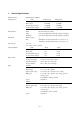
Interface Ribbon Type Ribbon Life Power Supply ” 14 .57 0m m 525 mm 20.6 7” 37 Options 230mm Power Consumption 9.06” Emulation Labels Backing sheet: 4.5" to 12" / 114 to 305mm Thickness: Backing sheet 0.0028" to 0.0035" / 0.07 to 0.09mm Total thickness 0.0075" / 0.19mm max. Envelope #10 9.4 × 4.
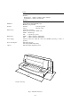
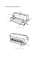
2. External Appearance and Composition Front cover Adjustment lever Paper guide Platen knob Power switch Interface connector Control panel Fig. 1-2 Front view of the Printer Release laber Fig.
Fig. 1-4 Front cover removed Fig.
3. Control Panel 3-1.
3-2. EDS Mode Settings Bank Switch A 1 2 B C 3 4 5 6 1 2 3 4 5 6 1, 2 3,4,5 D E F 6 1,2,3,4 1,2,3,4,5 1, 2, 3, 4, 5 Function ON Emulation Character Table (CT) Standard / EPSON mode IBM mode RAM Usage (Not used) Paper Out Detector (Not used) Graphics Direction Auto Tear-off (Long) Line Spacing Auto LF with CR Zero Style Strobe Timing Print Mode Draft ON (Not used) OFF Print Pitch 10cpi ON ON 12cpi OFF ON 17cpi ON OFF Quiet Page Length 11"/Letter ON ON ON 8" OFF ON ON 11.
4. Parallel Interface 4-1. General Specifications Item Interface Synchronization System I/F Protocol Logic Level Specifications Centronics-compatible Via externally supplied STROBE pulse Using ACK and BUSY signals Compatible with TTL level ACK t 4.1µs 4.1µs t t t Data STROBE (EDS B-6 : ON) STROBE (EDS B-6 : OFF) BUSY t : More than 0.5µs Fig. 1-6 Timing Charts for Parallel Interface 4-2.
5 Serial Interface (optional) When using the serial interface, the optional Serial-Parallel Converter must be connected to the printer. 5-1.
5-3. DIP Switch Settings Switch 1 2 3 4 5 6 7 8 ON 8 data bits No parity OFF 7 data bits Parity checked Handshaking protocols – see table below Odd parity Even parity Data transfer rate – see table below All switches are set to ON before the printer leaves the factory.
6. EE-PROM mode 6-1. Outline These settings can be changed in the EE-PROM mode by writing data directly to the EE-PROM on the main logic board: Setting EE-PROM mode • Send (09)H command. Canceling EE-PROM mode • Initialize the printer by sending @ 6-2. Explanation of special control codes @ Exits printer from EE-PROM mode and initializes the printer. M@ Returns all data in the EE-PROM to the factory settings. After the buffer is cleared, the buzzer sounds.
6-3.
Address 04H Function Factory data EDS setting IBM Code Page (Character Table=Graphics, IBM#1, #2) Function b0 b1 b2 b3 b4 Function #437 1 1 1 1 1 #3841 #850 0 1 1 1 1 #3843 #860 1 0 1 1 1 #3844 #861 0 0 1 1 1 #3845 #863 1 1 0 1 1 #3846 #864 0 1 0 1 1 #3847 #866 1 0 0 1 1 #3848 #3840 0 0 0 1 1 #852 International Character Set (Character Table=Italics) Function U.S.A.
Address Function Factory data 1AH, 1BH Top Margin in Auto-loading Tractor 1CH, 1DH Top Margin in Auto-loading Friction 1EH~21H Macro Set EPSON 48H 00H 48H 00H 00H 22H~25H Macro Set IBM 00H 00H 26H, 27H TEAR OFF (Short) 28H, 29H TEAR OFF (Long) 2AH, 2BH Initial Condition Area 2CH~54H Auto Start Area EPSON (41 byte) 00H 00H 80H 00H 80H FFH FFH 00H Auto Start Area IBM (41 byte) 00H 00H FF Control Code (Space 00H / Null 0FH) EE-PROM Check Code 00H 00H 01H 55H~70H 7EH 7FH – 15 –
6-4. Rewriting the EE-PROM Follow this procedure to rewrite the EE-PROM. (1) Turn the printer on. (2) Load a BASIC disk in the computer. (3) Turn the computer on. (4) Set a sheet of paper in the printer, and press the ON LINE switch. (5) Enter the program listed below and run the program. 10 LPRINT CHR$(27);CHR$(26);CHR$(&H09) 20 LPRINT CHR$(27);”MW1";CHR$(&H01);CHR$(&HFB) 30 LPRINT CHR$(27);”MR” BASIC Program Code What It Does 10 LPRINT CHR$(27);CHR$(26);CHR$(&H09) Enters the EE-PROM mode.
CHAPTER 2 THEORY OF OPERATION 1. Block Diagram (Main logic Board) .....................................................................19 2. Main Logic Board ................................................................................................20 2-1. General Flow Chart ............................................................................................... 20 3. Power Supply Circuit .......................................................................................... 21 4.
1. Block Diagram (Main logic Board) The block diagram of this printer is shown in Fig. 2-1. Data (From Host Computer) Print head Parallel interface LED Driver Carriage motor Masked ROM 2M CPU Detectors UVE-PROM 512K Driver Paper feed motor EE-PROM RAM Gate array Switch Control panel board Power supply unit AC Power Main logic board Printer mechanism Fig.
2. Main Logic Board 2-1. General Flow Chart The flow chart below shows you the general flow of editing and printing operations. POWER ON Initialization Ready state Read data Control code? No YES Control code processing NO Print? Data storage (Line buffer determination) YES Data processing or printing NO (Print out of data) Return? YES Return action Fig.
3. Power Supply Circuit A ringing choke converter type circuit is used with a dropper type circuit in the power supply unit, fulfilling the input and output conditions described in the chart below. Voltage Range Max. Current Output Service 110VAC, 120VAC 1.0 A Input 220VAC to 240VAC 0.6 A 5 VDC ±5% 0.4 A For logic circuit drive, for motor holding. Output For print head 33 VDC ±5% 1.25A drive, for motor drive.
4. Mechanism 4-1. Print Head Mechanism The print head consists of 9 needle wires and 9 print solenoids. The following explains how each needle wire operates during printing. (1) When the print solenoid is energized, the clapper is attracted by the iron core and the needle wire is driven toward the platen. (2) This needle wire hits the platen via the ink ribbon and paper. A single dot is printed on the paper.
4-2. Print Head Carrying Mechanism The print head carrying mechanism consists of a carriage, timing belt, carriage motor, and home position detector. Carriage The carriage is supported horizontally by the carriage stay and rear angle. The carriage moves from side to side with the print head mounted above it. A timing belt is clamped to the base of the carriage and a shield plate is mounted at the base for home position detection.
4-3. Ink ribbon feed mechanism The ink ribbon feed mechanism is linked to the print head carrying mechanism so the ink ribbon always winds automatically in the same direction while the carriage moves left and right. The movement of the carriage along the serrated edge of the rear angle of the printer mechanism drives the idler gear. The rotation of the idler gear is conveyed sequentially to the gears that work and wind the ribbon.
4-4. Paper Feed Mechanism The paper feed mechanism consists of a paper feed motor, an idler gear, a platen and a traction unit. The paper feed motor is a PM (Permanent Magnet) 4-phase and 48 pulse motor. There are two ways of feeding paper into the printer: the friction method and the tractor method. You can select the method you want to use by setting the release lever on the optional push tractor unit.
4-5. Detectors (1) Print head temperature detectors The A/D converter in the CPU detects the print head temperature at power on and before each line begins to print. +5V +5V Printer head Vref Thermistor R1 AN0 R2 CPU Fig. 2-8 Printer head temperature detector circuit Control Method Print Error stop (thermistor open) Normal print Unidirectional print Print stop Error stop (thermistor closed) (2) A/D Conversion Value POINT 0-5 6-213 214-221 222-251 252-255 AN Voltage V 0.00 0.00-4.35 4.35-4.48 4.
(3) Paper end Detector The paper end Detector is located in the paper chute unit. The A/D converter in the CPU detects the presence or absence of paper. +5V +5V R2 R1 Detecting signal Friction Detecting signal R5 R4 R3 Skew R8 R7 R6 Detecting signal Tractor R9 Fig. 2-10Paper end detector circuit Control Method Output (V) (4) Detection 0 No paper 5 Paper present Release lever switch and lever switch Adjustment +5V R2 R1 Detecting signal Leaf switch Fig.
CHAPTER 3 ADJUSTMENTS This printer has undergone various adjustments so that it will attain a given standard of performance. In this chapter, a brief explanation is given of the methods for making adjustments. Follow the instructions when performing maintenance inspections or when replacing parts to correct malfunctions. 1. Adjustment of Gap Between Print Head and Platen ........................................ 31 2. Adjustment of Timing Belt Tension .....................................................
1. Adjustment of Gap Between Print Head and Platen Remove the front case unit ,rear angle and ribbon holder [1] according to the procedures described in chapter 4. (Fig. 3-1) (2) Install rear angle [2]. (3) Set adjusting lever [3] to the second position from the bottom. (Fig. 3-1) (4) Position the center of the carriage unit [4] 55 mm from the left end of the platen assy [5]. (Fig. 3-2) (5) Measure the gap between platen [5] and head [6] using a gauge [7] . (Fig.
2. Adjustment of Timing Belt Tension (1) (2) (3) Remove the front case unit according to the procedures described in chapter 4. Move the carriage unit [1] up to the extreme right position. Move the screw [3] fixing tension lever assembly [2] approximately 1mm to loosen the tension, then tighten the screw. The timing belt tension [4] is determined by the spring [5].
CHAPTER 4 PARTS REPLACEMENT This chapter explains disassembly and reassembly of the printer. Note the following regarding disassembly and reassembly. 1. Disconnect the printer from the wall outlet before servicing it. 2. Assy is the reverse of disassembly unless otherwise specified. 3. After reassembly, coat the screw heads with locking sealant. 4. Lubrication information is not provided in this chapter. Refer to section 2 in chapter 5. 1. Front Case Unit...................................................
1. Front Case Unit (1) (2) (3) Turn off the power switch. Remove the power cord from the AC output socket. Remove • Platen knob unit [1] • Front case unit [2] Detach the five hooks marked A using the tool shown below. • Control board [3] Detach the two hooks. 2. Rear Case Unit (1) – 35 – Remove • Front case unit as described above 1.
3. 4. Ribbon Holder (1) Remove • Front case unit as described in section 1. • Two screws [1] • Rear angle [2] • Ribbon holder [3] Center the carriage unit, tile it, then remove the ribbon holder.
5. 6. Main Logic Board Unit (1) Remove • Printer mechanism as described in section 4. • Three screws [1] • Connector [2] • Main logic board [3] (1) Remove • Printer mechanism as described in section 4.
7. Print Head (1) (2) Remove • Front case unit as described in section 1. • Two screws [1] • Cable [2] • Print head [3] WARNING The print head gets hot after printing. Do not touch it until it cools. Adjust • Gap between print head and platen. Refer to section 1 of Chapter 3. Note: Fold the head cables according to the dimensions shown below. 19±1 10±1 Cat size (Double-sided tape) 0.5±0.5 — Double-sided tape 163±1 85±0.5 468±1 90°±1 108.
8. Fuse (1) (2) Remove • Front case unit as described in section 1. Inspect • Fuse F1 [1] Defective → Replace fuse as follows: AC voltage 110/120V 220V/240V Fuse Type 5TT2A-250V 215-1A-250V New fuse blown → Inspect circuit 9. Tractor Unit (1) Remove • Rear case unit as described in section 2. • Two hexagonal nuts [1] • Stop ring [2] • Release lever [3] • Tractor unit [5] Push tractor bushing [4] with a screwdriver and lift tractor unit [5].
10. Carriage Motor Assy (1) Remove • Rear case unit as described in section 2. • Screw [1] • Spring [2] Set tension lever assy [3] in the unlocked position. • Two screws [4] • Carriage motor unit [5] Note: When assembling the carriage motor assy, the tension lever assy [3] must be secured with the screw [1] when the spring [2] is in place. 11. Carriage Unit (1) Remove • Ribbon holder as described in section 3. • Print head as described in section 8.
12. Paper Feed Roller Assy (1) Remove • Carriage unit as described in section 11 • Four springs [1], [2], [6] • Four stop rings[7] • Two gears [3] • Two plain washer [4] • Tow paper feed roller Assy [5] (1) Remove • Rear angle [1] • Carriage motor unit [2] as described in section 8 • Home position detector [3] • Four roll pins [4] • Frame holder [5] 13. Frame Holder Note: Roll pins [4] should not be used again once they have been removed. Always use new ones.
14. Paper Guide Assy (1) Remove • Paper feed roller Assy as described in section 12. • Three screws [1] • Frame support (R) [2] • Stop ring [3] • Platen gear [4] • Gear [5] • Frame holder as described in section 13. • Four screws [6] • Two screws [7] • Two washers [8] • Paper guide assy [9] Note: Gears [4],[5] should not be used again once it has been removed. Always use a new one. 15. Platen Assy (1) – 42 – Remove Paper guide assy as described in section 14.
16. Paper Feed Motor Assy (1) Remove Platen assy as described in section 15. • Two screws [1] • Paper feed motor assy [2] (1) Remove • Paper feed roller A as described in section 12. • Right stop ring [1] • Right release shaft [2] Push inwards. • Left release shaft [2] Pull the shaft outwards until the slot is exposed. • Paper path change plate [3] 17. Paper Path Change Plate Note: Align the “∆” mark on the paper path change plate with the “∆” mark on the release gear.
18. Detector (1) [1] Remove • Paper guide assy as described in section 14. • Four detectors [1] Note: Secure the lead wires at one point using fasteners [2] .
CHAPTER 5 MAINTENANCE AND LUBRICATION 1. 2. Maintenance ......................................................................................................... 47 1-1. Cleaning ................................................................................................................ 47 1-2. Checks ................................................................................................................... 47 Lubrication ...................................................................
1. Maintenance In order to maintain the optimum performance of this printer and to prevent trouble, maintenance must be carried out according to the following items. 1-1. Cleaning (1) (2) Removal of dirt Wipe off dirt with a soft cloth soaked in alcohol or benzine. *Note: Do not use thinner, trichlene or ketone solvents because they may damage plastic parts. Also during cleaning, be careful not to moisten or damage electronic parts, wiring, or mechanical parts. Removal of dust, pile, etc.
2. Lubrication Lubrication is very important to maintain optimum performance and to prevent trouble. 2-1. Lubricant The type of lubricant greatly affects the performance and durability of the printer, especially in a low temperature environment. We recommend use of the grease and lubrication oils listed below for this printer Type of oil Product name Maker Grease MOLYKOTE EM-30L DOW CORNING ASIA LTD Lubricant Mobil 1 Mobil oil 2-2.
Fig.
Fig. 5-2 Lubricated Areas (Carriage unit ) [17] [18] 20 mm 10 mm [18] Fig.
Fig.
CHAPTER 6 TROUBLESHOOTING 1. Troubleshooting Procedures ............................................................................. 55 2. Unit Replacement Priority Chart ........................................................................ 56 3. Repair by Unit Replacement............................................................................... 57 4. Repair by Parts Replacement ............................................................................. 63 4-1.
1. Troubleshooting Procedures Troubleshooting is never easy because various problems arise depending upon the particular location of the breakdown. The following procedures should be taken in making repairs. (1) The first method is to make repairs through unit replacements. The two display codes appearing in the flow chart are defined as follows: 1) indicates main logic board replacement; and 2) indicates printer mechanism replacement, to be carried out if the problem has not been corrected.
2.
3. Repair by Unit Replacement START A * Turn power off. * Remove I/F cable. * Mount ink ribbon. * Set paper. * Move carriage to center. Turn power on. Carriage Moves? NO B YES Carriage operates normally? NO *1 See (6) and waveform in item 7 of Chapter 7. YES Carriage motor operating waveform is normal? *1 NO YES 1) Replace main logic board. 2) Replace printer mechanism. Replace printer mechanism.
1 NO On line lamp light? YES On line lamp signal is normal? NO Replace main logic board. Press on line switch to take off line. YES Replace control panel board. NO On line lamp is out? A YES E Press paper feed switch. Paper feed switch operation is normal? NO *2 See (7) and (8) waveform in item 7 of Chapter 7. Paper feed motor drive waveform is normal? *2 YES NO 1) Replace main logic board. 2) Replace printer mechanism. YES Turn power off. Replace printer mechanism.
2 Printing operation is normal? NO *3 See (4) and (5) waveform in item 7 of Chapter 7. Print head drive signal waveform is normal? *3 YES NO 1) Replace main logic board. 2) Replace printer mechanism. YES Replace printer mechanism. A Paper feed operation is normal? NO *2 See (7) and (8) waveform in item 7 of Chapter 7. Paper feed NO motor drive waveform is normal? *2 YES Ribbon feed operation is normal? YES Terminates self printing. YES NO 1) Replace ink ribbon. 2) Replace printer mechanism.
3 Printing begins? NO D YES Printing operation normal? NO YES 1) Replace I/F cable. 2) Replace main logic board. 3) Check host computer. Stop print program. END C B Carriage moves with hand? NO Replace printer mechanism. YES Output (+33V, +5V) of power supply unit is normal? *4 YES 1) Replace main logic board. 2) Replace printer mechanism. 3) Replace control panel board. NO Turn power off. Fuse blows out? YES NO Replace power supply unit. Replace fuse.
4 Output of power supply unit is normal? *4 NO YES Turn power off. Replace power supply unit. Connect connector CN6 from main logic board. Turn power on. Fuse blows out? NO YES Replace fuse. 1) Replace main logic board. 2) Replace printer mechanism. 3) Replace control panel board.
D *5 See (9) waveform in item 7 of Chapter 7. I/F signal is normal? *5 YES NO Ready condition? NO YES There is data transmission? YES NO Check hardware or host computer print program. I/F mode set up properly? NO Change I/F mode. YES 1) Replace I/F cable. 2) I/F cartridge 3) Replace main logic board. A C E On line switch goes ON/OFF? NO YES On line lamp drive signal is normal? NO YES Replace control panel board. Replace main logic board. A – 62 – 1) Replace control panel board.
4. Repair by Parts Replacement 4-1. Does not Operate at All with Power on START +33V, +5V are supplied? *1 NO DC Power abnormal. YES RESET signal becomes HIGH? *2 NO Check RESET circuit; replace parts. YES Crystal waveform is normal? *3 NO Check crystal circuit; replace parts. YES ROM OE signals become LOW? YES Carriage motor abnormal. Check operation. END See 4-2. Power Supply Circuit Abnormal. NO 1) Replace CPU or ROM. 2) Check relevant circuit.
4-2. Power Supply Circuit Abnormal (1) Remove connector CN101 from power supply unit. START Fuse F1 is blown? NO YES Replace Fuse F1 Fuse is blown again? YES NO Replace 1) Power supply unit The no load voltages are below: VH (33V) Line +33V ± 5% Between Pin 4 and Pin 3 of CN101 VL (5V) Line +5V ± 5% Between Pin 1 and Pin 2 of CN101 Check the 5V line of the main logic board.
4-3. Defective Motor Operation START Paper Feed Motor LF-CMN signal is normal? *4 NO YES LF-ø1, ø2, ø3, ø4 are normal? *5 YES START CR-ø1, ø2, ø3, ø4 are normal? *6 Check and replace 1) TR6 2) TR7 3) Gate array YES NO Replace CR motor Check and replace 1) TA1 2) CPU Check operation END Replace LF motor Check operation END *4 See (7) waveform in item 7 of Chapter 7. *5 See (8) waveform in item 7 of Chapter 7. *6 See (6) waveform in item 7 of Chapter 7.
4-4. Defective Print Head Operation START Does not print at all? NO YES +33V line is supplied? A specific pin does not work? NO NO YES YES Check and replace • TA3 (HD1, 2, 4, 6) • TA4 (HD3, 7, 8, 9) Check and replace 1) Power supply unit (Refer to item 4-2.) Check and replace 1) TR11 2) TR8 ~ TR10 3) Gate array Print is light as whole? YES NO Head energizing control signal is normal? *7 YES Check and replace 1) Print head Adjust gap (Refer to Chapter 3.
4-5. Defective Interface Operation START Press on line switch to take on line. Send print program from host computer. *8 See (9) waveform in item 7 of Chapter 7. Is I/F signal normal? *8 NO YES Incorrect print generated? YES NO Check I/F cable.
CHAPTER 7 PARTS LIST HOW TO USE PARTS LIST (1) (2) (3) (4) (5) (6) (7) DRWG. NO. This column shows the drawing number of the illustration. REVISED EDITION MARK This column shows a revision number. Part that have been added in the revised edition are indicated with “#”. Part that have been abolished in the revised edition are indicated with “*”. #1 : First edition → Second edition *1 : First edition → Second edition PARRTS NO. Parts numbers must be notified when ordering replacement parts.
1. Printer Assembly 1-1.
1-2. Parts List Printer Assembly DRWG.NO. REV. PARTS NO.
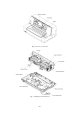
2. Printer Mechanism 2-1.
2-2. Parts List Printer Mechanism DRWG.NO. 1 2 3 4 5 6 6-1 6-2 6-3 7 8 9 10 11 12 13 14 15 16 17 18 19 20 21 22 23 24 25 26 27 28 29 30 31 32 33 34 35 36 37 38 39 40 41 42 43 44 45 46 47 48 49 REV. PARTS NO.
Printer Mechanism DRWG.NO. 50 51 52 53 54 55 56 57 58 59 60 61 REV. PARTS NO. 04020016 04020015 04012501 02440401 02210001 02206002 02020401 01903073 01903038 01903031 00630404 #2 03870405 PARTS NAME STOP RING SE4.0 STOP RING SE3.0 ROLL PIN SP2.5X10 WAVE WASHER WW4X8X0.2X1.5H PLAIN WASHER WF10X18X1.6 PLAIN WASHER WF6X13X1.
3. Sub - Assembly 3-1. Lower Case Unit DRWG.NO. 4-1 4-2 4-3 4-4 4-5 REV. PARTS NO.
3-2. Front Case Unit DRWG.NO. 7-1 7-2 REV. PARTS NO.
3-3. Serial-Parallel Converter ( Option ) 17-1 17-7 17-5 17-2 17-3 17-8 17-4 17-6 17-6 17-6 DRWG.NO. 17-1 17-2 17-3 17-4 17-5 17-6 17-7 17-8 – REV. PARTS NO.
3-4. Tractor Unit DRWG.NO. 2-1 2-2 2-3 2-4 2-5 2-6 2-7 2-8 2-9 2-10 2-11 REV. PARTS NO. 86436330 86436320 NPN 83200651 83101690 NPN NPN 80521090 04020017 04012002 02307050 PARTS NAME TRACTOR L ASSY TRACTOR R ASSY SHEET GUIDE TRACTOR BUSHING TRACTOR GEAR TRACTOR SHAFT TRACTOR STAY SPRING C090-060-0179 STOP RING SE5.0 ROLL PIN SP2.0X10 POLY-SLIDER WP7X0.
3-5. Carriage Unit DRWG.NO. 3-1 3-2 3-3 3-4 3-5 3-6 3-7 3-8 3-9 3-10 3-11 3-12 3-13 3-14 REV. PARTS NO. *2 #2 86432320 86432310 86432311 86060810 86032411 83912331 83904490 83200990 83120470 83101370 83100721 NPN NPN 80902220 80511150 PARTS NAME CLUTCH PLATE UNIT CARRIAGE ASSY CARRIAGE ASSY IDLER ASSY GEAR A ASSY GEAR COVER CARD HOLDER REAR ROLLER RIBBON CASSETTE GEAR GEAR 48X0.3 RF IDLER GEAR 37X0.3 ROLLER SHAFT ROLLER SHAFT TIMING BELT HTD102 446X4.
3-6. Frame Base Assy 5-3 5-3 5-1-3 5-1-2 5-1-3 5-1-2 5-3 a ab c b 5-1-1 5-1-3 5-1 5-1-2 c 5-3 5-2 5-4 DRWG.NO. 5-1 5-1-1 5-1-2 5-1-3 5-2 5-3 5-4 REV. PARTS NO.
3-7. Frame L Unit 11-1 11-3 a 11-1-3 11-1-2 c a b 11-1-4 11-1-5 b 11-1-1 11-1-3 11-3 c DRWG.NO. 11-1 11-1-1 11-1-2 11-1-3 11-1-4 11-1-5 11-2 11-3 REV. PARTS NO. #2 86430620 *2 87770210 #2 80705650 83904500 09090039 08300152 NPN NPN 00926603 11-2 11-1-5 PARTS NAME DETECTOR B UNIT CABLE ASSY B CABLE UNIT B DETECTOR HOLDER LEAF SWITCH LSA1119H PHOTO-INTERRUPTER RPI-574 HEAT-SHRINK TUBE F2-2.0 FRAME L ASSY SCREW TAT 2.
3-8. Frame R Unit DRWG.NO. 9-1 9-2 9-3 9-4 9-5 9-6 REV. PARTS NO. 86430440 NPN 83100510 83100110 04020010 01903064 PARTS NAME PAPER FEED MOTOR ASSY FRAME R ASSY GEAR 40X0.5 GEAR 26X0.5 STOP RING SE2.
4.
5. Electrical Parts 5-1. Main Logic Board 5-1-1.
– 85 –
5-1-2.
– 87 –
5-1-3. Parts List Main Logic Board DRWG.NO. IC1 IC2 IC3 IC4 IC5 IC6 IC7 IC8 IC9 D1 D2-3 D4-5 D6 ZD1-2 ZD3 TA1 TA2 TA3-4 TR1-3 TR4-5 TR6 TR7-8 TR9-10 TR11 TR12 TR13 C1 C2 C3 C4 C5-6 C7-10 C11-12 C13-14 C15-16 C17 C18 C19 C20-21 C22 C23 C24-31 C32-34 C35-36 C37 C38 C39-40 REV. PARTS NO.
Main Logic Board DRWG.NO. C41 C42-44 C45 C46 C47 CA1-3 CA4 R1 R2 R3-10 R11 R12 R13-15 R16 R17 R18 R19 R20 R21-22 R23 R24-25 R26-29 R30-33 R34-37 R38-41 R42 R43-44 R45 R46-47 R48 R49-50 R51-52 R53 R54 R55 R56 R57-58 R59-60 R61-62 R63-71 R72-74 R75-76 R77 R78 R79-81 R82-85 R86-88 R89-91 R92-94 R95 R96-98 R99 R100-101 RA1 RA2 RA3 REV. PARTS NO. NPN NPN NPN PARTS NAME CERA. CAPA. 0.022UF 50V CERA. CAPA. 1000PF 50V CERA. CAPA. 470PF 50V Q’TY 1 3 1 REMARKS NOT MOUNTED NPN NPN NPN CERA. CAPA. 0.
Main Logic Board DRWG.NO. CN1 CN2 CN3 CN4 CN5 CN6 CN8-9 CN10 CN11 JP1 JP2 JP3 REV. PARTS NO.
5-2. Control Panel Board 5-2-1. Circuit Diagram 5-2-2. Component Layout 5-2-3. Parts List Control Panel Board DRWG.NO. REV. PARTS NO.
5-3. Connected Board 5-3-1. Component Layout 5-3-2. Parts List Relay Board DRWG.NO. CN7 J118 REV. PARTS NO.
5-4. Power Supply Unit 5-4-1.
5-4-2.
5-4-3. Parts List Power Supply Unit DRWG.NO. R1 R2 R3 R4 R5 R6 R7 R8 R9 R10 R11 R101 R102 R103 R104 R105 R106 ZD1 ZD101 ZD102 C1 C2 C3-5 C6 C7 C8-9 C10 C11 C12 C13-14 C101 C102 C103 C104 CN101 D1 D2 D3 D101 D102 DB1 F1 IC101 REV. PARTS NO.
DRWG.NO. J10 J11 L1 L1-2 PC1 Q1 Q101 Q2 SW1 T1 W1-2 - REV. PARTS NO.
6. Serial - Parallel Converter Board ( Option ) 6-1.
6-2. I/F Board 6-2-1. Circuit diagram 6-2-2. Component Layout 6-2-3. Parts List DRWG.NO. IC101 IC102 R101 C101-104 C105 CN101 CN102 J101-108 REV. PARTS NO. 08200125 08200109 NPN NPN NPN 09100461 09100462 93930006 PARTS NAME IC-I/F LT1081CN IC-RESET M51953BL RD RESISTOR 3.3 K-OHM 1/6W CHEM. CAPA. 4.7UF 25V CAPACITOR 0.
6-3. CPU Board 6-3-1.
6-3-2. Component Layout 6-3-3. Parts List CPU Board DRWG.NO. IC1 IC2 TR1 R1 TR2-4 TR5 TR6-7 TR8 RA1 C1 C2 C3 C4 C5-6 XTAL1 DSW1 SW1 CN1A-1B CN2 REV. PARTS NO. PARTS NAME Q’TY 08250011 08221021 07603007 NPN 06751021 06754721 06783313 06754721 NPN NPN NPN NPN MASKED CPU HD63B01YF-IF SRAM HM6264LFP-100NS DIGITAL TRANSISTOR RTIN434C-T CHIP RESISTOR 4.7 K-OHM 1/10W CHIP RESISTOR 1 K-OHM 1/10W CHIP RESISTOR 4.7 K-OHM 1/10W CHIP RESISTOR 330 OHM 1/8W CHIP RESISTOR 4.7 K-OHM 1/10W RESIS. ARRAY 4.
7. Waveform with Oscilloscope (1) Crystal (12 MHz) (2) RESET (Power on reset) (4V) (2V) (0V) (0V) (4V) (0V) Crystal Pin 34 of IC1 Time/Div : 0.
(7) Paper Feed Motor Common Control Signal and Driving Signal (8) Paper Feed Motor Control Signal and Driving Signal (4V) (5V) (0V) (0V) (30V) (60V) (0V) (0V) Upper Lower : LF-CM Control SignalPin 39 of IC6 : LF-CM Driving SignalPin 1 of CN3 Time/Div : 20 ms Volt/Div : Upper 2V Lower 10V Upper Lower (9) Parallel Interface (parallel type Only) (5V) (0V) (4V) (0V) Upper Lower : STB : BUSY Time/Div Volt/Div Pin 1 of CN1 Pin 11 of CN1 : 50 ms : Upper 5V Lower 2V – 102 – : LF-ø1 Control Signal Pin
HEAD QUARTERS STAR MICRONICS CO., LTD. JAPAN OVERSEAS SUBSIDIARY COMPANIES STAR MICRONICS AMERICA INC. 536 Nanatsushinya, Shimizu, Shizuoka, 424, Japan 70-D Ethel Road West. Piscataway, NJ 08854-5950, U.S.A Tel: 732-572-5550 Telefax: 732-572-5693 Star House, Peregrine Business Park, Gomm Road, High Wycombe Bucks, HP13 7DL U.K. Tel: 01494-471111 Telefax: 01494-473333 STAR MICRONICS PTY. LTD. STAR MICRONICS ASIA LTD. STAR MICRONICS (N.Z.) LTD.