
Specifications
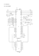


– 101 –
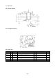
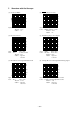
7. Waveform with Oscilloscope
(1) Crystal (12 MHz) (2) RESET (Power on reset)
Crystal Pin 34 of IC1 Upper : RESET input Pin 1 of IC8
Time/Div : 0.2 µs Lower : RESET output Pin 3 of IC8
Volt/Div : 1V Time/Div : 10 ms
Volt/Div : 2V
(3) Protection Circuit (4) Head Energizing Control Signal
Upper : RESET Pin 3 of IC8 Upper : HDEN Pin 57 of IC6
Lower : Drive Collector of TR13 Lower : HD1 Data Pin 47 of IC6
Time/Div : 5 ms Time/Div : 50µs
Volt/Div : Upper 2V Volt/Div : Upper 2V
Lower 2V Lower 2V
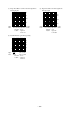
(5) Print Head Control Signal and Waveform (6) Carriage Motor Control Signal and Driving Signal
Upper : HD1 Data Pin 47 of IC6 Upper : Carriage-ø1 Control Signal Pin 38 of IC6
Lower : HD1 Pin 5 of JP2 Lower : Carriage-ø1 Driving Signal Pin 3 of CN5
Time/Div : 0.1 ms Time/Div : 1 ms
Volt/Div : Upper 5V Volt/Div : Upper 5V
Lower 10V Lower 20V
(2V)
(0V)
(4V)
(0V)
(4V)
(0V)
(4V)
(0V)
(4V)
(0V)
(0V)
(4V)
(0V)
(4V)
(5V)
(0V)
(0V)
(40V)
(20V)
(5V)
(0V)
(40V)
(0V)
(80V)