
Specifications


– 60 –
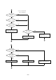
*4 Power Supply Unit
VH (33V) Line +33V ± 5% Between Pin 4 and Pin 3 of CN101
VL (5V) Line +5V ± 5% Between Pin 1 and Pin 2 of CN101
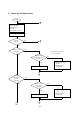
1) Replace I/F cable.
2) Replace main logic board.
3) Check host computer.
1) Replace main logic board.
2) Replace printer mecha-
nism.
3) Replace control panel
board.
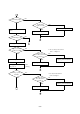
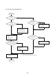
Replace printer mechanism.
Replace power supply unit.
C
D
NO
A
B
3
NO
NO
NO
YES
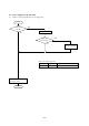
Printing begins?
YES
Printing
operation normal?
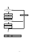
YES
Stop print program.
END
Carriage moves
with hand?
YES
Output
(+33V, +5V)
of power supply unit is
normal? *4
NO
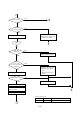
Turn power off.
Fuse blows out?
YES
Replace fuse.
Remove connector CN6 from
main logic board.
Turn power on.
4