EPSON IMPACT DOT MATRIX PRINTER EPSON LQ-670 SERVICE MANUAL SEIKO EPSON CORPORATION 4007875
NOTICE All rights reserved. Reproduction of any part of this manual in any form whatsoever without SEIKO EPSON’s express written permission is forbidden. The contents of this manual are subjects to change without notice. All efforts have been made to ensure the accuracy of the contents of this manual. However, should any errors be detected, SEIKO EPSON would greatly appreciate being informed of them.
PRECAUTIONS Precautionary notations throughout the text are categorized relative to 1) personal injury and 2) damage to equipment. WARNING CAUTION Signals a precaution which, if ignored, could result in serious or fatal personal injury. Great caution should be exercised in performing procedures preceded by WARNING Headings. Signals a precaution which, if ignored, could result in damage to equipment.
PREFACE This manual describes functions, theory of electrical and mechanical operations, maintenance, and repair of EPSON LQ-670. The instructions and procedures included herein are intended for the experience repair technician, and attention should be given to die precautions on the preceding page. The Chapters are organized as follows: CHAPTER 1. GENERAL DESCRIPTION Provides a general product overview, lists specifications, and illustrates the main components of the printer. CHAPTER 2.
REVISION SHEET Revision Issued Data Contents Rev.
TABLE OF CONTENTS CHAPTER 1. CHAPTER 2. CHAPTER 3. CHAPTER 4. CHAPTER 5. CHAPTER 6.
Chapter 1 Product Descriptions 1.1 Specifications .......................................................................................................1-1 1.1.1 Features................................................................................................................................... 1-1 1.2 Hardware Specifications......................................................................................1-3 1.2.1 Printing Method .................................................................
Chapter 1 Product Description 1.1 Specifications This specifications provide characteristics of the serial impact dot matrix printer LQ-670. 1.1.1 Features LQ-670 is a 24pin serial impact dot matrix printer for the VAR(value added reseller) market.
LQ-670 Service Manual Consumables and optional units Table 1-1.
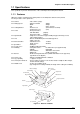
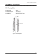
Chapter 1 Product Description 1.2 Hardware Specifications This section describes hardware specification for the LQ-670. 1.2.1 Printing Method Printing Method Number of pins Print pin arrangement Print pin diameter Color Print direction : Impact dot matrix : 24 pins : 12x2 staggered : 0.0079 inch (0.20 mm) : Black : Bi-direction with logic seeking Head Center Figure 1-2. Pin Configuration Rev.
LQ-670 Service Manual 1.2.2 Printing Specifications Copy capability :1 original + 4 copies Print speed and printable columns Table 1-2.
Chapter 1 Product Description 1.2.3 Paper Handling Specifications Feeding method Feeder Paper path :Friction feed Push tractor feed :Rear push tractor CSF Bin1/Bin2 (Option) Roll paper holder(Option) (front manual, rear CSF) (rear) :Manual Insertion Front in, front out CSF Rear in, front out Tractor Rear in, front out Line Spacing :1/6 inch or programmable in increments of 1/360 inch Feed speed :Refer to the table 1-4.
LQ-670 Service Manual 1.2.4 Paper Specification This section describes printable area and types of paper that can be used in this printer. Cut Sheets The following table shows specification for cut sheets. Table 1-7. Cut Sheet (Single sheet, Not Multi Part) Width (inch) (mm) Length (inch) (mm) Thickness(inch) (mm) 2 Weight (g/m ) (lb) Quality Front Entry(Manual Insertion) Rear Entry(CSF bin1) Rear Entry(CSF bin2) Minimum Maximum Minimum Maximum Minimum Maximum 3.6 11.7 3.9 11.7 3.9 11.
Chapter 1 Product Description Envelope Table 1-9. Envelope Specification Envelope (No.6) Width (inch) (mm) Length (inch) (mm) Envelope Width (inch) (No.10) (mm) Length (inch) (mm) Total thickness (inch) (mm) Weight Quality 2 (g/m ) (lb) Front Entry (Manual Insertion) Minimum Maximum 6.5 165 3.6 92 9.5 241 4.1 105 0.0063 0.0197 0.16 0.52 The difference of thickness at the printable area is within 0.0098 inch (0.25mm) 45 91 12 24 BOND paper, PLANE paper or AIR MAIL.
LQ-670 Service Manual Continuous paper (Single sheet and Multi part) Table 1-11. Continuous Paper (Single Sheet and Multi Part) Rear Entry (Tractor) Width Length(one page) Minimum 4 101.6 4 101.6 (inch) (mm) (inch) (mm) Copies Total thickness (inch) (mm) 2 Weight (g/m ) (not multi part) (lb) 2 Weight (g/m ) (one sheet of multi part) (lb) Quality Jointing Maximum 12 304.8 22 558.8 1 original + 4 copies 0.0025 0.
Chapter 1 Product Description Roll paper Table 1-13. Roll Paper Specification Width Length Thickness Weight Quality Rev. A (inch) (mm) (inch) (mm) (inch) (mm) 2 (g/m ) (lb) Rear Entry (Roll paper holder) Minimum Maximum 8.5 216 ----0.0028 0.0035 0.07 0.09 52 82 14 22 Plain paper, Reclaimed paper. Not curled, not folded, not crumpled.
LQ-670 Service Manual 1.2.5 Printable Area Cut sheets Printable Area Figure 1-4. Printable Area for Cut Sheet Table 1-14. Printable Area for Cut Sheet PW PL LM RM TM BM 1-10 (Width) (Length) (Left margin) (Right margin) (Top margin) (Bottom margin) Single sheet (Refer to section 1.2.4) (Refer to section 1.2.4) 3 mm or more(PW<=297mm) 3 mm or more(PW<=297mm) 0.0mm or more 0.0mm or more Multi part (Refer to section 1.2.4) (Refer to section 1.2.4) 3 mm or more(PW<=297mm) 3 mm or more(PW<=297mm) 0.
Chapter 1 Product Description Envelope and card RM LM TM Printable Area BM Figure 1-5. Printable Area for Envelope Printable Area Figure 1-6. Printable Area for Card Table 1-15. Printable Area for Envelope and Card PW PL LM RM TM BM (Width) (Length) (Left margin) (Right margin) (Top margin) (Bottom margin) Envelope (Refer to section 1.2.4) (Refer to section 1.2.4) 3 mm or more 3 mm or more 0.0mm or more *1 0.0mm or more Card (Refer to section 1.2.4) (Refer to section 1.2.
LQ-670 Service Manual Continuous paper Perforation Printable Area Perforation Figure 1-7. Printable Area for Continuous Paper Table 1-16. Printable Area for Continuous Paper PW PL LM RM TM BM 1-12 (Width) (Length) (Left margin) (Right margin) (Top margin) (Bottom margin) Continuous paper (Refer to section 1.2.4) (Refer to section 1.2.4) 13mm or more 13mm or more 4.2mm or more 4.2mm or more Rev.
Chapter 1 Product Description Roll paper PW LM BM TM Printable Area BM Figure 1-8. Printable Area for Roll Paper Table 1-17. Printable Area for Roll Paper PW PL LM RM TM BM Rev. A (Width) (Length) (Left margin) (Right margin) (Top margin) (Bottom margin) Continuous paper (Refer to section 1.2.4) (Refer to section1.2.4) 3mm or more 3mm or more 0.0mm or more 0.
LQ-670 Service Manual 1.2.6 Ribbon Cartridge Type Color Ribbon life Dimensions : Fabric : Black : 2 million characters (LQ 10cpi, 48 dots/character) :120.5mm(W) x 101.5mm(D) x 23.5mm(H) 1.2.7 Input data buffer 0 Kbyte or 64 Kbyte* Note*): Depends on default settings. 1.2.
Chapter 1 Product Description 1.2.
LQ-670 Service Manual 1.3 Firmware Specification This section provides detailed information about LQ-670 firmware. 1.3.
Chapter 1 Product Description Character tables :The standard version has 11 character tables and the NLSP version has 20 charater tables, as shown in the following table. Table 1-18.
LQ-670 Service Manual 1.3.2 Interface Specification This printer provides bi-directional 8-bit parallel interface and Type-B optional interface slot as standard. 1.3.2.1 Parallel interface (Forward channel) [Transmission mode] [Adaptable connector] [Synchronization] [Handshaking] [Signal level] : 8 bit parallel, IEEE-1284 compatibility mode : 57-30360 (Amphenol) or equivalent : /STROBE pulse : BUSY and /ACKNLG signals : TTL compatible (IEEE-1284 level 1 device) Table 1-19.
Chapter 1 Product Description BUSY signal is active (high level) under the following conditions. In the process of receiving data. In the condition of being input buffer full In the condition of being /INIT signal active(low level) During hardware initialization In the condition of being /ERROR or PE signal active(low level, high level, respectively) In the self test mode In the adjustment mode In the default-setting mode /ERROR signal is active(low level) under the following conditions.
LQ-670 Service Manual 1.3.2.
Chapter 1 Product Description 1.3.2.3 Optional Interface Type-B optional interface cards are available. Table 1-22. Optional Interface Reply message Main-Type ESC/P2 MT24p,PW106cl10cpi,PRG(W0xxxx)rev IBM 2390 Plus MT24p,PW106c110cpi,PRG(W0xxxx)rev Product-Name Emulation-Type Entity-Type LQ-670 ESCPL2-00 EPSONLQ2 LQ-670 PRPXL24-01 EPSONPRPXL24 1.3.2.4 Interface Selection The printer has 2 interfaces; the parallel interface and Type B optional interface.
LQ-670 Service Manual 1.4 Operation 1.4.1 Control Panel There are 7 switches and 8 LEDs on the panel as shown below. Operate Paper Out Pause Micro Adjust LF/FF 3sec Load/Eject Draft Roman Sans Serif Courier Prestige Script Others Font Condensed Tear Off/Bin Tear Off Bin 1 Bin 2 Card LED Off LED On LED Blinks Figure 1-10. Control Panel 1.4.1.1 Usual Operation Operate This switch turns the printer on and off. It is the secondary switch.
Chapter 1 Product Description Bin Pressing it selects CSF bin number or the Card mode* when cut sheet is used. Note*) Card mode is for using post card or envelope. Font Pressing it selects one of following fonts. Draft, Roman, Sans serif, Courier, Prestige, Script and Others *. Note*) Others means the font selected in the Default Setting Mode. Condensed Pressing it alternates condensed and non-condensed mode.
LQ-670 Service Manual 1.4.1.2 Switches Operation in normal mode In normal mode, pressing panel switches executes following function. Table 1-23. Operation in Normal Mode Switch Operate Pause Function Turn the printer on and off. Alternates printing and no-printing status. Enables Micro Adjust function, holding it down for 3 seconds. Loads or ejects the paper. Executes micro feed forward, when this function is enabled. Executes line feed, pressing it shortly.
Chapter 1 Product Description 1.4.1.3 Indicators(LED) This printer displays present conditions and errors on the indicators. Indication in normal mode Table 1-26.
LQ-670 Service Manual 1.4.1.4 Buzzer When the printer detects errors, it displays errors on the LEDs and also the buzzer beeps as warning sign. Table 1-27. Buzzer Warning sign Paper out error Paper jam error Paper eject error Release lever operation error Illegal panel operation Beeper sounds ❍❍❍ ●●●●● ❍❍❍ ●●●●● ❍ Note) ❍ : Beeper sounds approx. 100ms and interval is approx.100ms. ● : Beeper sounds approx. 500ms and interval is approx.100ms. 1-26 Rev.
Chapter 1 Product Description 1.4.2 Default Setting Setting Method Several printer settings loaded at each power-on can be changed in this operation. The method is described in the guidance sheets (language selection sheet and printer setting sheet) which are printed out at first in the setting mode if desired. User is requested to operate 2 switches watching 6 LEDs on the control panel. The lights turn on and off, and blink in one of the patterns described in the guidance sheets.
LQ-670 Service Manual Note*1): One of these fonts selected in the default setting is corresponding to others(=other fonts) on the control panel. Following fonts are not selected in the default setting mode. Draft, Roman, Sans serif, Courier, Prestige and Script Note*2) : These settings are effective when IBM 2390 Plus emulation is selected. Note*3): Settings with bold weight mean the standard factory settings.
Chapter 1 Product Description 1.4.4 Initialization Power-On initialization The initialization of this level is activated by power-on or cold reset command(remote RS command). This initialization is; to initialize the printer mechanism. to execute Operator initialization. Operator Initialization The initialization of this level is activated by /INIT signal(negative pulse). This initialization is; to clear the all buffers of data. to cancel the download character definition.
LQ-670 Service Manual 1.5 Main Components This printer consists of the following components. C214MAIN Board C214 PSB/PSE Board C214 PNL Board Printer Mechanism(M-5060) Housing 1.5.1 C214 Main Board This main board consists of 16bitCPU TMP96C041AF (IC11) which is driven by 17.
Chapter 1 Product Description 1.5.3 C214 PNL Board This panel board consists of one switch as power switch, 6 non lock type switches and 8 LEDs. 1.5.4 Printer Mechanism This unit consists of carriage mechanism, paper feed mechanism, cut sheet/transformer change over mechanism, platen gap adjustment mechanism and print head. 1.5.5 Housing The housing of this printer consists of upper housing, printer cover, front sheet guide, rear sheet guide and lower housing. Rev.
Chapter 2 Operating Principles 2.1 Printer Mechanism Operation..............................................................................2-1 2.1.1 Printing Mechanism ............................................................................................................... 2-1 2.1.2 Carriage Mechanism .............................................................................................................. 2-3 2.1.3 Ribbon Advance Mechanism.........................................................
LQ-670 Service Manual 2.1 Printer Mechanism Operation This section describes the printer mechanism(M-5060) and explains how it works. 2.1.1 Printing Mechanism The printing mechanism of this printer is composed of head, ink ribbon and ribbon mask. The print head is an 24-pin(12pins X 2) head for impact dot printing.(Refer to Chapter 1) Each wire has its own drive coil.
Chapter 2 Operating Principles Table 2-1. Print Head Specification Category Print Method Number of pin wires Wire diameter Print head life Weight Coil direct current resistance Response Frequency Drive Voltage Drive Condition Environmental condition Print drive method 2-2 Specification Impact dot matrix 24-pin (12X2) 0.20mm 200 million strokes/wire 115 ± 12g 39.3 ± 2.7 Ω (at 25 °C) Normal Mode : 1500Hz Buzzer : 1.
LQ-670 Service Manual 2.1.2 Carriage Mechanism Carriage Mechanism consists of the carriage movement mechanism and platen gap adjustment mechanism. Carriage Movement Mechanism The figure below shows carriage mechanism. The top of the carriage is supported by the CR guide frame, and down side is by the CR guide shaft. Since the carriage motor is stepping motor, the carriage moves freely, and the rotation of the motor is conveyed to the timing belt pulley and drive the timing belt.
Chapter 2 Operating Principles Table 2-3. CR Motor Specification Category Type Coil Resistance Drive Voltage Drive Resolution Drive Method Current Consumption Drive Frequency 2-4 Specification 200-pole, HB-type Stepping motor 3.5Ω ± 10% 42V±5% 0.106mm/step (1-2 phase) Constant current drive 1-2 phase, W1-2 phase Rated speed : 0.68A/phase At the waiting mode : 0.2A/phase 667∼7200Hz Rev.
LQ-670 Service Manual 2.1.3 Ribbon Advance Mechanism The ribbon advance mechanism consists of the rack mounted on the carriage guide frame, the pinion mounted on the carriage unit, planetary gear, combination gear and ratchet RD. When the carriage unit is moved right and left on the carriage guide shaft by the CR motor, the pinion is rotated by the rack and the motive power is conveyed to the planetary gear.
Chapter 2 Operating Principles 2.1.4 Paper Advance Mechanism The paper feed mechanism of this printer consists of the platen roller, paper feed roller, paper eject roller, PF motor, tractor unit, PW detector, PE (rear/front) detectors, release detector, and CSF mechanism(option). This printer performs paper advance by moving the paper horizontally.
LQ-670 Service Manual 2.1.4.2 Paper Advance Detector Mechanism Paper advance detector mechanism consists of PW detector and PE (rear/front) detectors. The function of this mechanism is to feedback information about monitoring paper edges, paper width and paper jam, and to control paper advance. The detector’s reading operation is constantly performed. The timing to feedback the red signals is necessarily selected by CPU according to the operation of PF motor and CR motor.
Chapter 2 Operating Principles Table 2-6. Front Paper End Detector Category Type Switch Rating Switch Mode Specification Mechanism type 0.6∼1.0mA, 5VDC ± 5% Paper in : Open Paper out : Close Table 2-7. Rear Paper End Detector Category Type Switch Rating Switch Mode Specification Mechanism type 0.6∼1.0mA, 5VDC ± 5% Paper in : Open Paper out : Close Table 2-8.
LQ-670 Service Manual 2.1.4.3 Release Lever Mechanism Release lever mechanism consists of the release lever, tractor transmission gear and the release detector. The setting of the release lever enables to add or release the pressure to the paper advance rollers and also to change over the tractor drive(continuous paper mode) which can be done by releasing or conveying the driving force of the PF motor to the tractor transmission gear and tractor gear, and the friction drive(cut sheet mode).
Chapter 2 Operating Principles 2.1.5 Platen Gap Adjustment Platen gap (the gap between platen surface and print head) allows the printer to use different thickness of paper by setting appropriate gap so that the different thickness of paper can avoid getting printing dirt or picking the ribbon accidentally. Adjustment mechanism consists of the CR guide shaft, parallelism adjustment bush, adjust lever and PG detector.
LQ-670 Service Manual 2.2 Power Supply Operation 2.2.1 Power Supply Circuit The power supply part of this printer consists of AC cable and power supply board. The power supply board provides CD current, which is necessary for the printer mechanism and control circuit. There are two kinds of board according to the input voltage; C214PSB(100-120VAC) and C214PSE(220-240VAC). Refer to the table below. Table 2-11.
Chapter 2 Operating Principles 2.2.1.2 Power Supply Circuit Operation In the power supply circuit, at first, the input AC power goes to the filter circuit, where removes the noise, and goes to the diode bridge for full-wave rectification and is smoothed by the electrolytic capacitor. Then it goes to the switching regulator on the primary side. This regulator uses ZC-RCC (ringing choke converter) type and effectively generates +42VDC in the secondary side.
LQ-670 Service Manual 2.2.2 Control Circuit This section describes main function of the control circuit. The main circuit is mounted on the C214 main board. 2.2.2.1 Operating Principles of the Control Circuit This printer’s control circuit includes a TM96C041AFCPU that runs at 17.20MHz, an E05B42 gate array, a 8M PROM, or 2M/4M Flash-ROM, 1M PS-RAM, 32M MROM, EEPROM, Reset IC and various drive elements. The table below shows each function of the main components of the main board. Table 2-13.
Chapter 2 Operating Principles 2.2.2.2 EEPROM Control Circuit EEPROM(IC9) uses three lines serial in/output 1kbit EEPROM and records default setting values and destination parameter. Control signals of EEPROM; CS,CK,DO, DI are attached in the CPU port P70∼73 and, are controlled. When the power off is detected, the CPU writes the necessary data to the EEPROM before the +5V line drops out of the normal range.
LQ-670 Service Manual 2.2.2.4 Power Off Detector Circuit Power-Down signal from the power supply board is sent to the port INTO of the CPU. The CPU initializes the port P26 and sends a signal to the manual reset port MRES in the Reset IC(IC12) in order to let IC12 to output the reset signal.(Refer to Figure 2-9) When the Power Down signal breaks into during the waiting mode, the CPU considers it as POWER-OFF immediately and performs POWER-OFF operation.
Chapter 2 Operating Principles 2.2.2.6 CR Motor Driver Circuit The CR motor driver circuit of this printer consists of CPU, gate array, CR motor drive IC SLA7024M (IC3) and CR motor. The CPU sends phase data; INA, /INA, INB and/INB from the port PGO0-3 to the CR motor IC. The current setting is de-coded in the CRFA0-3 and CRFB0-3 of the gate array by the CPU and is output to the CR motor drive IC. The CR motor driver IC outputs phase signals; CRA, /CRA, CRB, /CRB to the CR motor.
LQ-670 Service Manual 2.2.2.8 Operation Panel Control Circuit The panel control circuit consists of panel switches and gate array. The gate array detects the switch condition by the port SW0-SW5 and controls LED by LED0-9. Also, the POWER OFF signal(PSC) by the power switch on the operation panel is directly sent to the power supply circuit. Gate Array (IC10) Power Supply Circuit C214PSB/PSE PSC Operation Panel SW0-5 Switches LED0-9 LEDs POWER SW Figure 2-15. Operation Panel Control Circuit Rev.
Chapter 2 Operating Principles 2.2.2.9 Interface(I/F) Circuit The interface of this printer consists of gate array, parallel I/F connector and optional type-B I/F connector. Input of parallel I/F is pulled up by 3.3KΩ resistance and goes to 10Ω resistance, which is serially connected to the port DIN0-7 of the gate array. The output is done from the port in the gate array via LS06.
Chapter 3 Disassembly and Assembly 3.1 Overview.............................................................................................. 3-1 3.1.1 Precautions for Disassembling the Printer .............................. 3-1 3.1.2 Tools ........................................................................................... 3-1 3.1.3 Service Check After Repair ....................................................... 3-2 3.1.4 Specifications for Screws...................................................
3.2.16 DETECTOR, HP Removal....................................................... 3-24 3.2.17 DETECTOR, PG Removal....................................................... 3-24 3.2.18 DETECTOR, REL Removal..................................................... 3-24 3.2.19 DETECTOR, PE, FRONT Removal......................................... 3-25 3.2.20 DETECTOR, PE, REAR Removal ........................................... 3-26 3.2.21 LEVER, RELEASE Removal...................................................
Chapter 3 Disassembly and Assembly 3.1 Overview This section describes procedures for disassembling the main components of EPSON LQ670. Unless otherwise specified, disassembled units or components can be reassembled by reversing the disassembly procedure. Therefore, no assembly procedures are included in this section. Precautions for any disassembly or assembly procedure are described under the heading "WORK POINT".
LQ-670 Service Manual 3.1.3 Service Check After Repair After completing repair of the product, use the check list shown below, to verify status of repaired product and all the repair work performed before returning the product to the users. This list can be used as a record of all service work performed with the product. Table 3-2.
Chapter 3 Disassembly and Assembly 3.1.4 Specifications for Screws The table below lists the abbreviations used in this manual for small parts, such as screws and washers. Table 3-3. Abbreviations and Screw Type Abbreviation CB Description Cross-recessed Bind-head Screw CBS Cross-recessed Bind-head S-Tight Screw CBB Cross-recessed Bind-head B-Tight Screw CP Cross-recessed Pan-head Rev.
LQ-670 Service Manual 3.2 Printer Disassembly and Assembly This section describes procedures for disassembling the main components of the printer. Since re-assembling the printer can be done by simply performing the disassembly procedures in reverse order, this chapter does not describe the assembly procedures. If necessary, special notes on re-assembling or adjusting a component are given at the end of each procedure. CAUTION Before disassembling any part of the printer, note the warnings in Section 3.
Chapter 3 Disassembly and Assembly 3.2.1 HOUSING, UPPER Removal 1. Remove the platen knob from the printer. 2. Remove two screws (CBB/M4x14) fixing [COVER, WIRE] and remove it. 3. Disconnect the cable of the control panel from a connector CN15 on C214 MAIN board. 4. Remove two screws (CBB/M4x14) fixing [HOUSING, UPPER]. 5. Unhook two tabs fixing [HOUSING, UPPER] to lower housing, at both front and rear, and remove it by lifting it upward.
LQ-670 Service Manual 3.2.2 Printer Mechanism Removal 1. Remove [HOUSING, UPPER] (See Section 3.2.1) 2. Disconnect all cables of the Printer Mechanism from the C214 MAIN board: zCN5 (ÕPW Detector (Top)) zCN6 (ÕPrinthead (Front)) zCN7 (ÕPrinthead (Rear)) zCN8 (ÕPF Motor) zCN9 (ÕCR Motor) zCN10 (ÕREL Detector) zCN11 (ÕPG Detector) zCN12 (ÕHP Detector) zCN13 (ÕPE Detector (Rear)) zCN14 (ÕPE Detector (Front)) 3.
Chapter 3 Disassembly and Assembly 3.2.3 C214 MAIN Board Removal 1. Remove [HOUSING, UPPER] (See Section 3.2.1) 2. Remove Printer Mechanism (See Section 3.2.2) 3. Remove seven screws (5: CBB/M3x12, 2: CBS/M3x4) fixing the shield plate, and remove the shield plate. 4. Remove two screws (CBS/M3x12) fixing [COVER, CONNECTOR, UPPER], and remove [COVER, CONNECTOR, UPPER]. 5. Disconnect the cable of power supply unit from a connector CN3 on C214 MAIN board. 6.
LQ-670 Service Manual 3.2.4 C214 PSB/PSE Board Removal 1. Remove [HOUSING, UPPER] (See Section 3.2.1) 2. Remove the Printer Mechanism (See Section 3.2.2) 3. Remove the shield plate (See Section 3.2.3 at step 3) 4. Disconnect the cable of C214 PSB/PSE board from a connector CN3 on C214 MAIN board. 5. Remove the AC inlet assembly from a connector CN1 on C214 PSB/PSE board. 6. Remove three screws (CBB/M3x12) and one plane-washer fixing C214 PSB/PSE board to the lower housing, and take out C214 PSB/PSE board.
Chapter 3 Disassembly and Assembly 3.2.5 EP-ROM Replacement When the program ROM (EP-ROM) on C214 MAIN board need to be replaced (for program version-up), follow the instruction below. 1. Remove two screws (CBB/M4x14) fixing [COVER, WIRE] and remove it. 2. Remove the EP-ROM from the IC socket IC8 on C214 MAIN board. CHECK POINT When you remove or re-install the EP-ROM, be careful not to damage the lead terminals of the IC. EP-ROM COVER, WIRE Figure 3-6. EP-ROM Removal Rev.
LQ-670 Service Manual 3.2.6 Printhead Removal 1. Open the printer cover. 2. Remove two screws (CBS/M3x10) fixing the printhead to the carriage assembly, and remove the printhead. 3. Disconnect the cables connected to the printhead. CAUTION Make sure that C214 MAIN board operates correctly, before replacing the printhead to new one. Otherwise, it may be damaged again if C214 MAIN board is defective. CBS (M3x10) PRINTHEAD UNIT Figure 3-7.
Chapter 3 Disassembly and Assembly 3.2.7 Ribbon Mask Removal 1. Remove the printhead (See Section 3.2.6) 2. Remove the ribbon mask from the ribbon mask holder, by unhooking the tabs that hold the ribbon mask in place. CHECK POINT Be careful not to damage or deform the ribbon mask when you handle it. RIBBON MASK HOLDER RIBBON MASK Figure 3-8. RIBBON MASK Removal Rev.
LQ-670 Service Manual 3.2.8 PAPER EXIT ASSY. Removal 1. Remove [HOUSING, UPPER] (See Section 3.2.1) 2. Remove two screws (CBS/M3x6) fixing the Paper Exit Assy. to the Printer Mechanism. 3. First, slightly pulling the Paper Exit Assy. toward you, then lifting it upward to remove it. CHECK POINT When re-installing the Paper Exit Assy., fix it while pushing it against the Printer Mechanism. PAPER EXIT ASSY. Figure 3-9. PAPER EXIT ASSY. Removal 3-12 Rev.
Chapter 3 Disassembly and Assembly 3.2.9 Ribbon Mask Holder Removal 1. Remove [HOUSING, UPPER] (See Section 3.2.1) 2. Remove the Printhead (See Section 3.2.6) 3. Remove the Paper Exit Assy.(See Section 3.2.8) 4. Unhook the cables (to Printhead / PW Detector) from a cable hook on the Carriage Assy. 5. Unhook two tabs fixing the Ribbon Mask Holder to the Carriage Assy., and slightly pulling it forward. 6.
LQ-670 Service Manual Cable (to PW DETECTOR) CARRIAGE ASSY. (viewed from right-hand side) CR Guide Shaft PW DETECTOR ROLLER, PF, DRIVE RIBBON MASK HOLDER Figure 3-11. Cable Rooting 3.2.10 PW Detector (Top) Removal 1. Remove [HOUSING, UPPER] (See Section 3.2.1) 2. Remove the Printhead (See Section 3.2.6) 3. Remove the Paper Exit Assy. (See Section 3.2.8) 4. Remove the Ribbon Mask Holder (See Section 3.2.9) 5. Remove one screw (CB/M2.5x6) fixing the PW Detector (Top) and remove it.
Chapter 3 Disassembly and Assembly 3.2.11 MOTOR, CR Removal 1. Remove the Printer Mechanism (See Section 3.2.2) 2. Unhook the cable of [MOTOR, CR] from a cable hook at the bottom of the Printer Mechanism. 3. Remove [TENSION SPRING, 14.5] attached at the top right of the Printer Mechanism, to loosen the timing belt. 4. Remove four screws (CBS/M3x6) fixing the CR motor assembly to the Printer Mechanism, and remove it. 5. Remove two screws (CBS/M3x6) and remove [MOTOR, CR] from [MOUNTING PLATE, MOTOR, CR].
LQ-670 Service Manual 3.2.12 Carriage Assy. Removal 1. Remove the Printer Mechanism (See Section 3.2.2) 2. Remove [TENSION SPRING, 14.5] attached at the top right of the Printer Mechanism, to loosen the timing belt. 3. Remove [CAP, LEVER] and [HOLDER, ADJUST, LEVER]. 4. Remove an hexagonal nut which fixing the adjust lever to the carriage guide shaft, and remove the adjust lever. 5. Take out the head FFC from the cable holder at the bottom of the Printer Mechanism. 6.
Chapter 3 Disassembly and Assembly CAP, LEVER LEVER, PULLEY, DRIVEN HOLDER, ADJUST, LEVER TENSION SPRING, 14.5 SHAFT, LEVER, PULLEY, DRIVEN Adjust Lever Hexagonal Nut Figure 3-14. CARRIAGE ASSY. Removal (1) GUIDE, CR CARRIAGE ASSY. CR GUIDE SHAFT Figure 3-15. CARRIAGE ASSY. Removal (2) Rev.
LQ-670 Service Manual 3.2.12.1 RATCHET, RD Removal 1. Remove the Carriage ASSY. (See Section 3.2.12) 2. Remove the Ribbon Cartridge Holder from the Carriage ASSY., by unhooking three tabs. 3. Take out [RATCHET, RD] from the Ribbon Cartridge Holder. CHECK POINT When re-installing the Ribbon Cartridge Holder to the Carriage ASSY., first, hook the bottom part of the Ribbon Cartridge Holder to the Carriage ASSY. and hold it. Then, turn up the upper side of the Ribbon Cartridge Holder to the Carriage ASSY.
Chapter 3 Disassembly and Assembly 3.2.13 PAPER GUIDE Removal 1. 2. 3. 4. 5. 6. 7. Remove the Printer Mechanism. (See Section 3.2.2) Remove the paper exit ASSY. (See Section 3.2.8) Remove the carriage ASSY. (See Section 3.2.12) Remove the CR motor cover from [FRAME, CR] and [MOTOR, CR]. Remove [DETECTOR, HP] and [DETECTOR, PG]. Remove [GEAR, 20] from [FRAME ASSY., RIGHT] by unhooking a tab. Remove four screws (CBS/M3x6) fixing [FRAME,CR] to the frame assembly RIGHT and LEFT, and remove [FRAME, CR]. 8.
LQ-670 Service Manual ROLLER, PF, DRIVE GEAR, 16 Hook GEAR, 36 COMBINATION GEAR, 8, 30 Hook Figure 3-18. PAPER GUIDE ASSY. Removal (2) CBS (M3x6) FRAME, CR CBS (M3x6) Figure 3-19. PAPER GUIDE ASSY. Removal (3) 3-20 Rev.
Chapter 3 Disassembly and Assembly ROLLER, PF, DRIVE Shaft Holder Retaining Ring (#2) (E-shaped) Shaft Holder Figure 3-20. PAPER GUIDE ASSY. Removal (4) Slit of PAPER GUIDE PAPER GUIDE Actuator (DETECTOR, PE, REAR) CBS (M3x6) CBS (M3x6) Figure 3-21. PAPER GUIDE ASSY. Removal (5) Rev.
LQ-670 Service Manual 3.2.14 Platen Removal 1. 2. 3. 4. 5. Remove the Printer Mechanism (See Section 3.2.2) Remove the Paper Exit ASSY. (See Section 3.2.8) Remove the Carriage ASSY. (See Section 3.2.12) Remove the Paper Guide (See Section 3.2.13) Rotate the platen shaft holder at the both ends of the platen, to match a tab to a cutout of the frame assembly. 6. Slide the platen to left once, and remove it to upward.
Chapter 3 Disassembly and Assembly 3.2.15 MOTOR, PF Removal 1. Remove the Printer Mechanism (See Section 3.2.2) 2. Take out the cable of [MOTOR, PF] from the cable holder at the bottom of Printer Mechanism. 3. Remove tow screws (CBS/M3x6) fixing [MOTOR, PF] to [FRAME ASSY., LEFT] and remove it. MOTOR, PF (located inside [FRAME ASSY., LEFT]) CBS (M3x6) Figure 3-23. MOTOR, PF Removal Rev.
LQ-670 Service Manual 3.2.16 DETECTOR, HP Removal 1. Remove the Printer Mechanism (See Section 3.2.2) 2. Unhook [DETECTOR, HP] form [FRAME, CR] and remove it. 3. Disconnect the cable from [DETECTOR, HP]. 3.2.17 DETECTOR, PG Removal 1. Remove the Printer Mechanism (See Section 3.2.2) 2. Unhook [DETECTOR, PG] from [FRAME ASSY., RIGHT] and remove it. 3. Disconnect the cable from [DETECTOR, PG]. 3.2.18 DETECTOR, REL Removal 1. Remove the Printer Mechanism (See Section 3.2.2) 2.
Chapter 3 Disassembly and Assembly 3.2.19 DETECTOR, PE, FRONT Removal 1. Remove the Printer Mechanism (See Section 3.2.2) 2. Remove the Paper Exit ASSY. (See Section 3.2.8) 3. Unhook the detector holder from both the Paper Guide Frame and a shaft of [ROLLER, PF, DRIVE]. 4. Unhook [DETECTOR, PF, FRONT] from the holder and remove it. CHECK POINT Make sure to hook the detector holder to [ROLLER, PF, DRIVE] when reinstalling it. DETECTOR, PE, FRONT Holder Figure 3-25.
LQ-670 Service Manual 3.2.20 DETECTOR, PE, REAR Removal 1. Remove the Printer Mechanism (See Section 3.2.2) 2. Unhook three tabs of [HOLDER, CABLE, LOWER] at the bottom of the Printer Mechanism, and remove it from the Printer Mechanism. 3. Remove a screw (CBS/M3x6) fixing [DETECTOR, PE. REAR]. 4. Remove the detector holder from [FRAME, BASE] by unhooking the fixing tabs and remove it. 5. Unhook [DETECTOR, PF, REAR] from the holder and remove it. DETECTOR, PE, REAR Figure 3-27.
Chapter 3 Disassembly and Assembly 3.2.21 LEVER, RELEASE Removal 1. Remove the Printer Mechanism (See Section 3.2.2) 2. Remove two E-shaped retaining rings (#4) that fixing [LEVER, RELEASE] to [FRAME ASSY., RIGHT]. 3. Remove [LEVER, RELEASE] from [FRAME ASSY., RIGHT], together with [COMBINATION GEAR, 16, 16]. CHECK POINT Be careful not to lose [GEAR, 20] and a washer when removing [LEVER, RELEASE] as they may be popped out by [COMPRESSION SPRING, 20].
LQ-670 Service Manual 3.2.22 Tractor ASSY. Removal 1. Remove the Printer Mechanism (See Section 3.2.2) 2. Remove two hexagonal nuts fixing [SHAFT, TR, GUIDE] at the both side of the mechanism. 3. Rotate the shaft holder attached to the right end of [SHAFT, TR, DRIVE] to match the tabs to a cutout of [FRAME ASSY., RIGHT], and remove it. 4. Remove the Tractor ASSY. from the Printer Mechanism. CHECK POINT When re-assemble the Tractor ASSY.
Chapter 4 Adjustments 4.1 Adjustment Overview ...........................................................................................4-1 4.1.1 Required Adjustments ........................................................................................................... 4-1 4.1.2 Required Adjustment Tools ................................................................................................... 4-1 4.2 Adjusting and Resetting the Printer........................................................
Chapter 4 Adjustments 4.1 Adjustment Overview 4.1.1 Required Adjustments This section describes what adjustments are required after any part is removed or replaced. The following table shows the relationship between the repaired item and the adjustment. Table 4-1.
LQ-670 Service Manual 4.2 Adjusting and Resetting the Printer 4.2.1 Platen Gap Adjustment This adjustment consists of platen parallelism adjustment and platen gap adjustment. Parallelism adjustment is to adjust parallelism of track(CR guide shaft) that platen roller and print head moved. Since the core of parallelism adjustment bushing is tilted to the CR guide shaft, it is possible to move the CR guide shaft closer to or away from the platen roller by rotating the bushing.
Chapter 4 Adjustments 4.2.2 Factory Setting 1. 2. 3. 4. 5. Unplug the cable of the printer from the AC socket. Connect the printer and the PC by the parallel interface cable. Plug in the cable of the printer and turn on the printer. Set the release lever at the tractor side and also set the 12-inch continuous paper (1p). Load “GWBASIC” and execute the adjustment program. Following menu will be displayed. 3URJUDP /4 D 6HWWLQJ 95 95 95 ✼✼ ✼ ✼ >3ULQW VHOHFW@ SLQV ! SLQV 6.
LQ-670 Service Manual 9. In this menu, Select 106 column by moving the cursor with the ↑or ↓ and press ENTER key. After the selection is made, the following menu is displayed. 3URJUDP /4 D 6HWWLQJ '()67' SLQV 95 95 95 ✼✼ ,Q OLQH ✼✼ > 0DLQ 0(18 @ %L ' $GMXVW (QYHORSH ! )) SDSHU 68% 0(18 $ +RUL]RQWDO 3 &XW VKHHW $ 3 &XW VKHHW 10. In this menu, select FF paper by moving the cursor with the ↑or ↓ and press ENTER key.
Chapter 4 Adjustments 4.2.3 Bi-d Adjustment Bi-d adjustment can be done either by the panel operation or adjustment program. This section describes Bi-d adjustment by the program. 1. 2. 3. 4. 5. Plug off the cable of the printer from the AC socket. Connect the printer and the PC by the parallel interface. Plug in the cable of the printer and turn on the printer. Set the release lever to the tractor side and set the 12-inch continuous paper(1p). Load “GWBASIC” and execute the adjustment program.
LQ-670 Service Manual 8. If 4 lines are not straight vertically, you can adjust by changing setting values with ← or→ key. If the second and fourth lines are printed right side, compared with the first and third lines, change the setting value by pressing ← key. Then, printing pattern with the new setting will be printed by pressing SPACE key. If the second and fourth lines are printed left side, compared with the first and third lines, change the setting value by pressing → key.
Chapter 5 Troubleshooting 5.1 Overview................................................................................................................5-1 5.2 Unit Level Troubleshooting .................................................................................5-2 5.3 Repairing the Power Supply Circuit Board ......................................................5-11 5.4 Repairing the Main Board ..................................................................................5-14 5.
LQ-670 Service Manual 5.1 Overview This chapter contains flowcharts and checkpoint tables to help you troubleshoot the printer. Flowcharts let you isolate a faulty unit based on abnormal symptoms. The checkpoint tables let you identify the faulty part or unit by checking the values or ranges listed for each component. Units Exchange Repair of the primary side Repair of the secondary side Repairing Power Supply Board Repairing Main Board Repairing Printer Mechanism END Figure 5-1.
LQ-670 Service Manual 5.2 Unit Level Troubleshooting You may be able to identify the defective unit just from the symptom displayed. The table below provides the symptoms for a number of failures. Once you identify the problem, refer to the flowchart listed in the right-hand column of the table below to determine the cause of the problem. Table 5-3. Symptoms and Problem Descriptions Symptom The printer does not operate even when the power is turned on.
LQ-670 Service Manual [Printer does not work when the power is turned on ] Go back to START Is the NO power supply voltage normal? Input normal power supply. YES Is the fuse on the power supply board disconnected? NO Is output voltage of the power supply board normal?(Refer to Table 5-4) YES NO YES Replace the main control board. Replace the fuse F1 and remove all output connectors.
LQ-670 Service Manual [Printer goes error conditions when the power is turned on] START Select an error type.(Refer to Table5-2) YES Foreign objects Is it fatal error? NO Is power supply on or under the CR gudie shaft? If so, remove it. YES Is +42Vof CN2 in the power supplyboard normal? normal? NO Normal? NO power, move the carriage manually.
LQ-670 Service Manual [Abnormal printing during the self-test] Perform sel-test Are all NO the dots printed OK? YES Does NO the printer print? B YES Does the carriage move? NO YES Measure the coil resistance of the print head. Is NO coil resistance normal? Replace the print head. YES NO Normal? YES Is printing result YES Reset the adjust abnormally lever. dark or light? NO Print YES somethingelse? NO Go to other trouble shooting.
LQ-670 Service Manual [Abnormal paper feed] Is the paper set correctly? NO Set the paper correctly. YES Turn off the power supply. Rotate the platen knob manually and check if it rotates smoothly. Does the knob rotate smoothly? YES Replace the printer mechanism. Is the PF motor driven normally when the power is turned on? Turn on the power. Check if the paper is fed by SW on the panel. YES NO Replace the printer mechanism.
LQ-670 Service Manual [Abnormal control panel operation] Turn the power on without feeding paper Does the LED indicate paper out? NO YES Check output voltage of the power supply board. Is voltage normal? YES Replace the control panel Operate each switch to test the printer operation, checking LED indications. Are all switches&LED displays normal? NO NO Replace the control panel YES Replace the power supply board. Normal? YES NO Replace the main board.
LQ-670 Service Manual [Abnormal operation at power on] Perform the self-test. Is the self-test normal? NO Go to other troubleshooting YES NO Is the I/F mode set "Auto"? Set I/Fmode "Auto" by the control panel operation. (Default setting) YES Exchange the interface cable. YES Normal? NO Replace the Main Board YES Normal? NO Replace the powersupply board. END Figure 5-7. Flowchart 6 5-8 Rev.
LQ-670 Service Manual Table 5-4. Output Voltage of the Power Supply Board Connector No. Pin No. 1.2 3,4 5.6 7,8 CN2 Output voltage GP +42V GL +5V Note) Each head coil resistance can be measured between the number of each common terminal and the same wire number. Direct current resistance: 39.3±2.7Ω (at 25 °C) R F R L View A 1-24 :Wire Number C :Common Terminal T:Thermistor Terminal Figure 5-8. Print Head Connector Pin Alignment Rev.
LQ-670 Service Manual Refer to the tables below and it can be easily determined if a particular part is defective or not by checking the coil resistance of the motor or continuity of the transistor using multimeter. Table 5-5. Coil Resistance of the Motor Connector No. CN9 (CR motor) Common pin No. 5 Test pin No. Test method Meter Reading 1,2,3,4 3.5Ω±10% (At 25 °C) -- 1,2,3,4 Place one lead of the multimeter on pin 5 and the other lead on each terminal of 4-phase.
LQ-670 Service Manual 5.3 Repairing the Power Supply Circuit Board This section explains problems related to the power supply circuit board(C214PSB). Since the table below lists likely causes according to the order of frequently seen symptoms, find an appropriate symptom and check the checkpoint. Table 5-8. Repairing the C214PSB Board Symptom Normal voltage is not output. Condition Even the fuse F1 is replaced, it shorts soon. All output voltage is defective.
LQ-670 Service Manual Table 5-9. Repairing C214PSB Board (Con.) Symptom Normal voltage is not output. Condition All output voltage is defective. •If +42V is not output normally, other voltages become abnormal. Cause T1 is defective. Diode D51 is defective. All the output voltage is defective Power supply control signal line(PSC) is shorted. Over current protection circuit is defective. Over voltage protection circuit is defective.
LQ-670 Service Manual Table 5-10. Repairing the C214PSB Board (Con.) Symptom Normal voltage is not output. Condition All the output voltage is defective Cause +42V stabilization circuit is defective. Checkpoint Check the waveform of 1pin in the Photo coupler PC1. If it is unloaded, the waveform with periodical pattern can be seen. •If the waveform is abnormal, the elements around PC1, ZD51, ZD81∼85, or peripheral elements are defective.
LQ-670 Service Manual 5.4 Repairing the Main Board Refer to the following table for repairing the main board. Table 5-11. Repairing the C214 Main Board Symptom The printer does not work at all. Condition Reset signal is not canceled. Cause Defective operation of the reset circuit VOUT signal is output. CPU does not work. Clock signal is not generated. Checkpoint After the power is turned on, check 1pin of IC12 stays LOW for a while.
LQ-670 Service Manual Table 5-12. Repairing C214 Main Board (Con.) Symptom Printer goes to error state. Condition Fatal error. Cause +42V monitor circuit is defective. Carriage control circuit is defective. Checkpoint Check the voltage of 3 or 4 pin in CN3. •If the voltage is normal, CPU is defective. Check the output signal of pin 1, 8,11,18 and input signal of pin 5, 6,16,17 of IC3. •If the phase signal of the motor is not input, gate array IC25 is defective.
LQ-670 Service Manual Table 5-13. Repairing the C214 Main Board (Con.) Symptom Paper feed operation is abnormal. Condition PF motor control is abnormal. Cause PF motor control circuit is defective. Checkpoint Check the phase signal of pin 8 and output signal of pin 1 and pin 15 of IC1 or IC2. •If phase signal of the motor is not input, gate array IC10 is defective. •If the drive wave form is not output, IC1 or IC2 is defective. Solution Replace the main board, IC1 or IC2.
LQ-670 Service Manual 5.5 Repairing the Printer Mechanism This section provides instruction for repairing the printer mechanism. It describes various problems, symptom, likely causes, checkpoints, and solutions. Table 5-14. Repairing the Printer Mechanism Symptom CR motor is abnormal Carriage does not move even after the power is turned on. Condition CR does not move even the power is turned on. CR motor rotates, but carriage does not move. Cause Foreign objects are attached to mechanism.
LQ-670 Service Manual Table 5-15. Repairing the Printer Mechanism (Con.) Symptom Paper feed is abnormal. Condition Printing is performed, but no paper feed, or paper feed is not done smoothly. Cause PF motor is defective. Ribbon feed is abnormal. The ribbon is not fed. The ribbon cartridge is defective. Printing result is dirty. False printing Ink spots or dirt are seen around the printing area. Printing is performed even if there is no paper. Ribbon is caught or stuck by the ribbon mask.
Chapter 6 Maintenance 6.1 Preventive Maintenance.......................................................................................
Chapter 6 Maintenance 6.1 Preventive Maintenance Preventive Maintenance is important to keep the printer in the best condition and to prevent troubles in advance. Use the denatured alcohol to clean the exterior case and use the vacuum cleaner if necessary, to remove dust and paper debris in the printer inside. CAUTION ; Do not use thinner, trichloroethylene, or ketone-based solvents on the plastic components of the printer.
LQ-670 Service Manual Figure 6-1. Lubrication Points 6-2 Rev.
Appendix A.1 Connector Summary........................................................................................... A-1 A.2 Circuit Diagram ................................................................................................... A-5 A.3 Component Layout.............................................................................................. A-8 A.4 Exploded Diagram............................................................................................. A-10 A.
LQ-670 Service Manual A.1 Connector Summary Figure A-1 illustrates how primary components are connected. Table A-1 summarizes functions and sizes of the connectors. AC Power Supply Power supply board Main Board Printer Mechanism CN3 CN5 PW(TOP) Detector CN6 Print Head Paralle I/F CN1 CN7 Type-B I/F CN2 CN8 PF Motor CN9 CR Motor CN10 Release Detector CN11 PG Detector CN12 HP Detector CN13 (Rear)PE Detector CN14 (Front) PE Detector CN1 CN2 CN15 Control Panel Figure A-1.
Appendix Table A-2. Connector Pin Assignment-CN3 Pin 1 2 3 4 5 6 7 8 9 10 I/O ----------------O I Signal GP GP +42V +42V GND GND +5V +5V PWDN PSC Function Ground Ground +42VDC +42VDC Ground Ground +5VDC +5VDC Power-down signal Power switch Table A-3. Connector Pin Assignment-CN5 Pin 1 2 3 4 I/O ------I Signal A +5V GND E Function +5VDC +5VDC Ground PW(TOP) Detector Table A-4.
LQ-670 Service Manual Table A-5. Connector Pin Assignmen-CN7 Pin 1 2 3 4 5 6 7 8 9 10 11 12 13 14 15 I/O O O O O O ------O O O O O O O Signal Name HD3 HD11 HD2 HD19 HD7 +42V +42V +42V HD22 HD15 HD18 HD23 HD10 HD14 HD6 Function Pin 3 drive signal Pin 11 drive signal Pin 2 drive signal Pin 19 drive signal Pin 7 drive signal +42VDC +42VDC +42VDC Pin 22 drive signal Pin 15 drive signal Pin 18 drive signal Pin 23 drive signal Pin 10 drive signal Pin 14 drive signal Pin 6 drive signal Table A-6.
Appendix Table A-11. Connector Pin Assignment-CN13 Pin 1 2 I/O I --- Signal Name PE[REAR] GND Function (Rear) PE detector signal GND Table A-12. Connector Pin Assignment-CN14 Pin 1 2 I/O I --- Signal Name PE[FRONT] GND Function (Front) PE detector signal GND Table A-13.
LQ-670 Service Manual A.2 Circuit Diagram Figure A-2. C214Main Board Circuit Diagram Rev.
Appendix : Heat Sink (Q1, D51) Figure A-3. C214PSB Board Circuit Diagram A-6 Rev.
LQ-670 Service Manual : Heat Sink (Q1, D51) Figure A-4. C214PSE Board Circuit Diagram Rev.
Appendix A.3 Component Layout Figure A-5. C214 Main Board Component Layout A-8 Rev.
LQ-670 Service Manual Figure A-6. C214 PSB Board Component Layout Figure A-7. C214 PSE Board Component Layout Rev.
Appendix A.4 Exploded Diagram Figure A-8. Exploded Diagram A-10 Rev.
LQ-670 Service Manual Figure A-9. Exploded Diagram Rev.
Appendix Figure A-10. Exploded Diagram A-12 Rev.
LQ-670 Service Manual Table A-14. Parts Reference Table Ref. No. 100 101 102 103 104 105 106 107 108 109 110 111 112 113 114 115 116 117 118 119 120 121 122 123 124 200 300 330 400 450 500 501 502 503 504 505 506 507 508 509 510 511 512 513 514 515 516 517 518 Rev.
Appendix Table A-15. Parts Reference Table (Con.) Ref. No. 519 520 521 522 523 524 526 527 528 529 530 531 532 533 534 535 536 537 538 539 540 541 542 543 544 545 546 547 548 549 550 551 552 553 554 555 556 557 558 559 560 561 562 563 564 565 566 567 A-14 Description Combination Gear 9.
LQ-670 Service Manual Table A-16. Parts Reference Table (Con.) Ref. No 568 569 570 571 572 573 575 576 577 578 579 580 581 582 583 584 585 586 587 588 589 590 591 592 600 601 602 603 604 605 606 607 608 609 610 611 612 613 650 Rev. A Description Tension Spring 14.5 Compression Spring 1.47 Tension Spring 0.55 Compression Spring 1.96 Compression Spring 1.47 Compression Spring 1.96 Right Frame Assembly Left Frame Assembly Bushing Assembly Driven PW P.C.
Appendix A.5 Dimension and Weight Exterior Dimension Body only : 469mm (W) X 390mm (D) X 256mm (H) Body including CSF 1 bin : 469mm (W) X 620mm (D) X 446mm (H) Body including CSF1 & 2 bins : 469mm (W) X 693mm.(D) X 446mm (H) Weight Body only : About 9.1Kg Body including CSF 1bin : About 10.9Kg Body including CSF 1& 2 bins : About 11.7Kg Figure A-11.Dimension of LQ-670 A-16 Rev.
EPSON OVERSEAS MARKETING LOCATIONS EPSON AMERICA, Inc. EPSON DEUTCHLAND GmBH 20770 Madrona Avenue, P.O. Box 2842 Torrance, CA 90509-2842 Phone: (800)922-8911 Fax: (310)782-5220 EPSON UK LTD. Zülpicher Straße 6, 4549 Düsseldorf Germany Campus 100, Maylands Avenue, Hemel Hempstead, Herts, HP2 7TJ U.K. Phone: (+44)01442-61144 Fax: (+44)01442-227227 EPSON IBERICA, S.A. 68 bis, rue Marjolin 92300, Levallois-Perret France Phone: (1)4087-3737 Telex: 610657 EPSON ITALIA S.P.A. Avda.
EPSON SEIKO EPSON CORPORATION