EPSON TERMINAL PRINTER LX-1050+ SERVICE MANUAL EPSON 4003283 ,’ ,,
NOTICE All rights reserved. Reproduction of any part of this manual in any form whatsoever without SEIKO EPSON’s express written permission is forbidden. The contents of this manual are subjects to change without notice. All efforts have been made to ensure theaccuracyof the contents of this manuaI. However, should any errors be detected, SEIKO EPSON would greatly appreciate being informed of them.
PRECAUTIONS Precautionary notations throughout the text are categorized relative to 1) personal inju~ and 2) damage to equipment. DANGER Signals a precaution which, if ignored, could result in serious or fatal personal injury. Great caution should be exercised in performing procedures preceded by DANGER Headings. WARNING Signals a precaution which, if ignored, could result in damage to equipment.
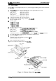
PREFACE This manual describes functions, theory of electrical and mechanical operations, maintenance, and repair of LX-105O+. The instructions and procedures included herein are intended for the experience repair technician, and attention should be given to the precautions on the preceding page. The chapters are organized as follows: CHAPTER 1. GENERAL DESCRIPTION Provides a general product overview, lists specifications, and illustrates the main components of the printer. CHAPTER 2.
REVISION SHEET Revision Issue Date Revision Page Rev.
TABLE OF CONTENTS CHAPTER 1. CHAPTER 2. CHAPTER 3. CHAPTER 4. CHAPTER 5. CHAPTER 6.
Chapter 1 General Description Table of Contents 1.1 FEATURES 1-1 1.2 SPECIFICATIONS 1.2.1 Printing Specifications. . . . . . . . . . . . . . . . . . . . . . . . . . . . . . . . . . . . . . . 1.2.2 Paper Handling Specification. . . . . . . . . . . . . . . . . . . . . . . . . . . . . . . . . . 1.2.3 Paper Specification . . . . . . . . . . . . . . . . . . . . . . . . . . . . . . . . . . . . . . . . . 1.2.4 Ink Ribbon . . . . . . . . . . . . . . . . . . . . . . . . . . . . . . . . . . . . . . . . . . . . .
List of Tables Table 1-1. Options for LX-105O+ . . . . . . . . . . . . . . . . . . . . . . . . . . . . . . . . . . . . 1-1 Table 1-2. Print Speed and Printable Columns . . . . . . . . . . . . . . . . . . . . . . . . . l-s Table Table Table Table Table Table Table Table l-3. CharacterTables. . . . . . . . . . . . . . . . . . . . . . . . . . . . . . . . . . . . . . . . I-A -4. Adjust Lever Settings . . . . . . . . . . . . . . . . . . . . . . . . . . . . . . . . . . . . 1-6 -5.
General Description LX-105O+ Service Manual 1.1 FEATURES The LX-105O+ is a small, light-weight, low-cost, advanced paper handling printer. Its main features are: The LX-105O+ has four Standard version: India version: Russian version: Latin version: South Europe version: versions. Different parts are Program ROM version only. ROM version SOxxxx ROM version Slxxxx ROM version S2XXXX ROM version S3xxxx ROM version S4xxxx c1 Command compatible with following printers.
LX-105O+ Service Manual General Description Table 1-1 lists the optional units available for the LX-1050+. Table 1-1. Options for LX-105O+ Cat. No. 8143 New Serial Interface Board C82302*/C82304* 32KB Serial Interface C82303* 32KB Parallel Interface 8165 IEEE-488 Interface Board C80624* Single Bin Cut Sheet Feeder i C80014* 8755 1-2 Description [ PullTractorUnit Ribbon Cartridge Rev.
General Description LX-105O+ Service Manual 1.2 SPECIFICATIONS This section provides detailed statistics for this printer. 1.2.1 Printing Specification Printing Method: Serial, impact, dot matrix Pin Configuration: 9 wires (diameter 0.29rnm) #1 #2 #3 #4 #5 b &--=- 0.29 mm 0.35 mm(l/72”) I #8 #7 #8 #9 Figure 1-2. Pin Configuration Print speed: Bi-directional printing with logical seeking (Text mode) Uni-directional (left to right) printing (Bit image mode) See Table 1-2.
LX-105O+ Service Manual General Description lot matrix format: 9 X 9 Text mode (Draft) 18X 20 Text mode (NLQ Ytaracter sets: ~haracter tables: 13 international character sets See Table 1-3. Table 1-3.
General Description LX-105O+ Service Manual 1.2.2 Paper Handling Specification 1/6 inch or 1/8 inch, or programmable in units of 1/216 inch Approximately 95 ms (1/6 inch line feed) Approximately 75 ms (1/6 inch in page feed) Friction feed Tractor feed (push tractor: standard, pull tractor: optional) Line spacing: Line feed speed: Paper feed method: Rear Paper insertion: 1.2.3 Paper Specification Useable paper: Width: 182 to 364 mm (4 to 14.3 inch) Length: 182 to 364 mm (4 to 14.
LX-105O+ Service Manual General Description Continuous paper 345.4 mm max. I 13 mm min. ➤ 4---D I 13 mm min. o o Printable area 0 0 0 0 0 0 0 .———————————— n u c1 0 0 0 0 0 0 Figure 1-4. Printable Area - Continuous Paper The adjust lever must be set to the proper position for the paper thickness. Adjust lever settings Table 1-4. Adjust Lever Settings I I Lever position 0.06 to 0.18 mm 2nd step I Paper Thickness I I 3rd step 0.19 to 0.
General Description LX-105O+ Service Manual 1.2.4 Ink Ribbon Type: #8755 Ribbon Cartridge Color: Reliability: Black 3 million characters at 14 dots/character 1.2.5 Environmental Conditions Temperature: -30 to60“C - Storage 5to35“C - Operation Humidity: 5 to 85 YO RH (no condensation) - Storage 10to801%0 RH (no condensation) - Operation Resistance to shock: 2 G, 1 ms - Storage 1 G, 1 ms - Operation 0.50 G (55 Hz max.) - Storage 0.25 G (55 Hz max.) - Operation Resistance to vibration: 1.2.
LX-105O+ Service Manual General Description 1.3 INTERFACE OVERVIEW The LX-105O+ is equipped with the following external interfaces; ■ ■ Centronics parallel interface Optional Type A interface 1.3.1 Parallel InterFace Data Format Synchronization 8-bit parallel Handshaking By BUSY and ACKNLG signal Ill-compatible By STROBE pulse Signal Level Adaptable Connector 57-30360 (arnphanol) or equivalent Table 1-6 shows the comector pin assignments and signal functions of the parallel interface.
General Description LX-105O+ Sewice Manual —. . . . -. . — . . .- . . Table 1-6. Connector Pin Assignments and Signal Functions (Cont.) Pin No. Signal Name 1/0 Description 12 PE o This signal indicates whether paper is available in the printer or not. A HIGH level indicates a no paper condition. 13 SLCT o pulled up to +5V though 3.
LX-105O+ Service Manual General Description 1.4 PRINTER OPERATIONS This section describes the basic operations of the printer. 1.4.1 Control Panel The control panel of this printer contains four non-lock type push buttons and four LED indicators for easy ope;ation of the various printer function. [Buttons] D POWER 0 ON LINE D READY m PAPER OFF LINE OUT NLQ III I CONON J D E N S E D OFf= J LOAD/EJECT ROMAN JJ SANS SERIF J J J FORM FEED ~ J II LINE FEED Figure 1-7.
LX-105O+ Service Manual General Description 1.4.2 SelecType Functions SelecType allows the user to choose fonts and the printing mode easily. This function provides for selection of Draft, Roman, or Saris Serif fonts and selection of normal printing or condensed printing modes. SelecType is effective only when the printer is ON LINE and not printing. To select Roman or Saris Serif, press the NLQ button. A buzzer sounds when the NLQ button is pressed. When it sounds twice, the Roman font is selected.
L.X-1050+ Service Manual General Description 1.4.5 DIP Switch Settings The two DIP switches are located on the side of the printer and function as shown in Tables 1-7 throum 1-10. Note that the status of the DIP switches is read only at power on or upon receipt of the INIT signal. Table 1-7. Settings for DIP Switch I I I Description SW No. 1-2 1 1-3 1-4 Shape of Zero 12 cpi 10 cpi 0 0 OFF OFF 1 I OFF OFF See Table 1-10.
General Description LX-105O+ Service Manual Table 1-9. Character Table Selection (DIP SW 1-5: ON) Sw 1-6 Sw 1-7 Sw 1-8 India version ~:pj:;d :?:/:: Latin Version South Europe Version ON ON ON PC437 PC437 PC437 PC437 PC437 ON ON OFF PC850 PC437 PC866 PC852 PC857 ON OFF ON PC860 PC437 PC869 MAZOWIA ISO Lat. IT ON OFF OFF PC863 PC437 Bulgaria Code MJK PC437G.
LX-105O+ Service Manual General Description 1.4.6 Buzzer Operation The buzzer sounds under the following conditions: BEL code: Carriage trouble: PaperQut: Abnormal voltage: Incorrect SRAM: Incorrect RAMinside CPU: Recognition of panel operation: Factory setting: Sheet ejection failure (in CSF mode): Illegal paper release/ unrelease: The buzzer sounds for 0.1 second when a BEL code is input. Beeps 6 times, pausing briefly after 3rd beep. Beeps 20 times, pausing briefly after every 4 beeps.
Ganeral Description LX-105O+ Service Manual 1.5 MAIN COMPONENTS The main components of the LX-105O+ printers are designed for easy removal and replacement to maintain/repair the printers. The main components are: Cl TAMA board: Main control board. The CPU on this board controls all main functions. D TAPNL-W control panel: Control panel. Cl TAa filter unit: Transformer and filter board. D M-3D60: Printer mechanism. 1.5.1 TAMA Main Control Board The TAMA board is the main controller of this printer.
LX-105O+ Service Manual General Description 1.5.2 TAa Filter Unit The TAa filter unit contains a power cord (120V Version) or AC inlet (220/240V Version), power switch, fuse filter circuit, and power transformer. 120V Version 220/240V Version Figure 1-9. TAa Filter Unit 1.5.3 Printer Mechanism (M-3D60) The M-3D60 printer mechanism was developed specifically for the LX-105O+ printer.
Chapter 2 Operating Principles Table of Contents 2-1 2.1 OVERVIEW 2-1 2.2 OPERATING PRINCIPLES OF THE PRINTER MECHANISM 2.2.1 Printhead Printing Operation . . . . . . . . . . . . . . . . . . . . . . . . . . . . . . . . . . 2-2 2.2.2 Carriage Drive Mechanism . . . . . . . . . . . . . . . . . . . . . . . . . . . . . . . . . . . 2-3 2.2.2.1 Home Position Sensor . . . . . . . . . . . . . . . . . . . . . . . . . . . . . . . . 2-3 2.2.3 Paper Feed Mechanism Operation . . . . . . . . . . . . . . . . . . . . . .
List of Tables Table 2-1. Ribbon-Feed Gear Train. . . . . . . . . . . . . . . . . . . . . . . . . . . . . . . . . . 2-7 Table 2-2. Voltage Applications . . . . . . . . . . . . . . . . . . . . . . . . . . . . . . . . . . . . . 2-8 Table 2-3. Functionsofthe Main ICand Circutis . . . . . . . . . . . . . . . . . . . . . . . 2-10 Table 2-4. Phase-Excitation Method . . . . . . . . . . . . . . . . . . . . . . . . . . . . . . . .
Operating Principles LX-105O+ Service Manual 2.1 OVERVIEW This section describes the operating principles of the printer mechanism and the electrical circuits of the LX-105O+. 2.2 OPERATING PRINCIPLES OF THE PRINTER MECHANISM The LX-105O+ printer mechanism is composed of the printhead unit, paper feed mechanism, carriage drive mechanism, and various sensors. The figure below shows a block diagram of the printer mechanism.
LX-105O+ Service Manual Operating Principles 2.2.1 Printhead Printing Operation The dot-wire operation during printing is as follows. When the head-driving coil for a dot wire is energized, the actuating plate, which is engaged to one end of the dot wire, is attracted to the iron core, and drives the dot wire toward the platen. The dot wire forcefully pushes both ribbon and paper against the platen, causing a dot to be printed.
Operating Principles LX-1050+ Service Manual 2.2.2 Carriage Drive Mechanism The carriage mechanism includes the printhead, the carriage, the timing belt, the carriage motor, and the platen. The timing belt is connected to the bottom of the carriage. The belt is driven by the carriage motor and moved via the beltdriven pulley. The printhead is mounted on the carriage, and the entire unit is moved right and left along the carriage guide shaft and plate.
LX-105O+ Service Manual Operating Principles 2.2.3 Paper Feed Mechanism Operation Friction feeding is used for cut sheets, and push tractor feeding is used for fanfold paper. Friction-Feed Operation The paper is held against the platen by paper-feed rollers. The paper-feed motor rotates the platen gear, via the paper-feed reduction gear, in the direction shown in following figure.
Operating Principles LX-105O+ Service Manual Push Tractor Feed Operation When the push tractor unit is used, the paper is set such that its holes mesh with the tractor pins along the tractor belt. The paper feed motor is driven and, via the pinion on the motor shaft, rotates the gears in the direction shown in following figure, rotating the tractor belts. This causes the paper advances in the direction indicated by the arrow.
LX-105O+ Service Manual Operating Principles 2.2.3.1 Paper End Sensor Following figure show the paper end sensor. This sensor switch is ON when no paper is in place (e.g., when the paper supply has run out.). Paper ~ 2 “Paper present” Figure 2-7. Paper End Sensor Mechanism 2.2.3.2 Release Sensor The release sensor senses the position of the release lever in order to detect whether tractor feed or friction feed is in effect. Fric/ion/Tractor Sensor Figure 2-8. Release Sensor Mechanism 24 Rev.
Operating Principles LX-105O+ Service Manual 2.2.4 Ribbon Advance Mechanism The ribbon-feed mechanism consists of the ribbon cartridge and the ribbon-feed section. The ribbondriving gear is always driven counterclockwise (regardless of the timing belt direction) via the gear trains shown in following table. Table 2-1.
LX-105O+ Service Manual Operating Principles 2.3 OPERATING PRINCIPLES OF THE ELECTRICAL CIRCUITRIES This section describes principles of electrical circuitries. 2.3.1 Operating Principles of the Power Supply Circuit using the TAa Fiher Unit (which combines a filter and a power transformer) and the T14NfA board. The Ac input passes first through the filter circuit, where line noise is removed, and is then set to the transformer, where it is stepped down into two separate voltages: AC 26V and AC 12C.
Operating Principles LX-105O+ Service Manual 2.3.2 Operating Principles of the Main Control Circuit The printer CPU is an 8-bit CPU ~D7810HG running at 15 MHz. It oversees control of all the components of the printer. The E05A30 gate array contains various memory management functions that control the assignment of the memory and 1/0 areas. Bm CPU vPD781OHG (2C) ~c”’””’ E E05A30 (3B) I CR motor driver Control Panel Parallel l/F EIE m Figure 2-11.
LX-105O+ Service Manual Operating Principles Table 2-3. Functions of the Main IC and Circuits Looation Functions 2C Receives data from the host computer and loads the data to the input buffer in RAM. Expands the input data held in the buffer to create image data. Loads this image data to the image buffer in RAM. Transfers the image data to the printhead drive circuit. Also controls various parts of the printer mechanism, such as the motors. E05A30 3B The gate array E05A30 functions areas follows 1.
Operating Principles LX-105O+ Service Manual 2.3.2.2 Sensor Circuit Following figure shows the sensor circuit in block diagram. The PAO of CPU port senses carriage home position. The PA1 senses paper end. The PA2 senses release lever position. The AN5 of CPU A/D convertor senses +24V line voltage. HOME PAO PE PA1 RELEASE PM +24V line AN5 CPU uPD7810HG (2C) Figure 2-14. Sensor Circuit 2.3.2.3 Carriage Motor Drive Following figure shows a block diagram of the carriage motor drive circuit.
LX-1050+ Service Manual Operating Principles 2.3.2.4 Paper Feed Motor Drive Circuit The paper-feed motor drive circuit is shown in following figure. me paper-feed motor is a step motor which can utilize 2-2 phase excitation. When the paper-feed signal PC2 is set to HIGH, Q20 and Q16 are turned on, and +24 V is supplied to the motor. When the paper-feed motor is not driven, +5 V is supplied, via resistor R42 and diode D6, to hold the motor.
Operating Principles LX-105O+ Service Manual 2.3.2.5 Printhead Drive Circuit Gate array E05A30 is used as an 8-bit + l-bit data latch. The CPU determines the pulse width for the head-wire drive pulses from gate array E05A30 by monitoring the printhead drive power (+24 V line). The E05A30 gate array includes circuitry to interface the CPU and the printhead. The data is output to the printhead in the following sequence: Print data is expanded in the image buffer as dot patterns.
LX-105O+ Service Manual Operating Principles 2.3.2.6 Host Interface The host interface circuit is shown in following figure. STROBE pulses from the host computer pass through the low-pass filter, consisting of R72 and C12, and flow into the STROBE terminal. These pulses latch the parallel data and set the BUSY signal HIGH, so that subsequent data transfer is inhibited. At this time, the CPU, by reading address OCO02H, can detect whether the data from the computer are latched in the gate array.
Operating Principles LX-105O+ Service Manual 2.3.2.7 EEPROM Circuit The EEPROM stores in its memory the current feed position of continuously fed paper, as well as the current panel settings. This memory is retained even after power is shut off. EEPROM can memorize the current position of continuously fed paper, so that this information can be maintained even if power goes off. Following figure shows the EEPROM circuit. Note that this is external to the CPU’s memory space.
Chapter 3 Disassembly and Assembly Table of Contents 3.1 GENERAL REPAIR INFORMATION 3-1 3-2 3.2 DISASSEMBLY AND ASSEMBLY 3.2.1 Printhead Removal . . . . . . . . . . . . . . . . . . . . . . . . . . . . . . . . . . . . . . . . . 3-2 3.2.2 Removal of Casing . . . . . . . . . . . . . . . . . . . . . . . . . . . . . . . . . . . . . . . . . 3-4 3.2.2.1 Upper Casing Removal. . . . . . . . . . . . . . . . . . . . . . . . . . . . . . . . 3-4 3.2.2.2 Control Panel Removal. . . . . . . . . . . . . . . . . . . . . .
Figure 3-25. Paper Guide Plate Removal. . . . . . . . . . . . . . . . . . . . . . . . . . . . Figure3-26. Adjust l_everRernoval . . . . . . . . . . . . . . . . . . . . . . . . . . . . . . . . Figure 3-27. Tractor Frame l-Removal . . . . . . . . . . . . . . . . . . . . . . . . . . . . . Figure 3-28. Extraction ofTractorunti . . . . . . . . . . . . . . . . . . . . . . . . . . . . . . Figure 3-25. Tractor Phase Alignment . . . . . . . . . . . . . . . . . . . . . . . . . . . . . . . . . . .
Disassembly and Assembly LX-105O+ Service Manual 3.1 GENERAL REPAIR INFORMATION This chapter describes the procedures for removin~ replacins and adjusting the main components of the LX-105O+. Prior to beginning any of these procedures, be certain that the AC power cord is disconnected. To help prevent hands jiotn being cut by the printer mechanism or sharp plate edges, wear gloves when performing these procedures.
LX-105O+ Service Manual Disassembly and Assembly 3.2 DISASSEMBLY AND ASSEMBLY This section details the disassembly procedures for the LX-105O+. As a rule, reassembly is performed by simply reversing the procedures; a number of special notes, however, are provided under the heading “Notes for Reassembly.” When a disassembly or reassembly procedure requires that an adjustment be performed, the adjustment is described under the heading, “Required Adjustment.
LX-105O+ Service Manual Disassembly and Assembly [Step 3] Unlock the two levers securing the printhead to thecarnage bypulhngthemdown. Then lift and remove the printhead. P Levers Figure 3-2. Printhead Removal [Step 4] Disconnect the head cable from theconnector ontheprinthead. Rev.
LX-105O+ Service Manual Disassembly and Assembly 3.2.2 Removal of Casing This section details the procedure for removing the upper casing and the control panel. 3.2.2.1 Upper Casing Removal [Step 1] Remove the sheet guide unit, printer cover, paper tension unit, and paper feed knob. [Step 2] Pull in the two notches securing the push tractor to the printer mechanism, and remove the push tractor from the printer mechanism. Figure 3-3. Push Tractor Removal [Step 3] Remove the two C.B.
Disassembly and Assembly LX-105O+ Service Manual [Step 5] While lifting the upper casing, discomect the cable of the control panel from connector CN3 on the TAMA board. Then remove the upper casing. Figure 3-5. Upper Casing Removai -2 NOTE FOR REASSEMBLY: Before reassembling the upper casin& prepare the FFC (Flat Flexible Cable) that connects the Control Panel and TAMA board in such a way that it can be connected to the Panel Cable Sailed Plate. Control Panel Figure 3-6. Control Panei FFC Rev.
Disassembly and Assembly LX-105O+ Service Manual 3.2.2.2 Control Panel Removal [Step 1] Remove the upper casing (as described in the previous section). [step 2] Turn the upper casing over, push in the two notches on the casing that are securing the control panel to it, and remove the control panel. anel Figure 3-7. Control Panel Removal 3-6 Rev.
Disassembly and Assembly LX-105O+ Service Manual 3.2.3 Removal of Circuit Boards This section describes the procedure for removing the TAMA Board and the TA-a filter unit. 3.2.3.1 TAMA Board Removal [Step 1] Remove the upper casing (See section 3.2.2.1). The following connectors on the TAMA —board, which are connecting it to external components, should be disconnected: CN4, CN5, CN6, CN7, CN8 FFC (Flexible Flat Cable), and CN9. Do not pull roughly on the connectors, or you may damage the board.
LX-1050+ Service Manual Disassembly and Assembly 3.2.3.2 TA-a Filter Unit Removal [Step 1] Remove the upper casing (See section 3.2.2.1). [Step 2] Disconnect connector CN9 at the TAMA board. This comector comects the TA-a filter unit. [Step 3] Remove the C. B.(O) (M4 x 8) screw securing the frame ground wire. [Step 4] Remove the two C. B.B-tite (M4 x 12) screws and two C.B.(O) (M4 x 8) screws securing the filter unit, and then remove the unit.
Disassembly and Assembly LX-105O+ Service Manual 3.2.5 Disassembly of Printer Mechanism This section details the removal of components from the printer mechanism. 3.2.5.1 Removal of Carriage Motor [Step 1] Remove theprintermechanism (See section 3.2.4). [Step 2] Disconnect the motor cable from the carriage motor. [Step 3] Remove the belt tension spring EOO1 from the base frame. [Step 4] Remove the timingbelt fromthebeltpulley.
Disassembly and Assembly LX-105O+ Service Manual 3.2.5.2 Removal of Home-Position Sensor [Step 1] Remove the printer mechanism. (See section3.2. 4) [Step 2] Turn the printer mechanism upside-down. [Step 3] Push in the notch securing the home-position sensor, and remove the sensor from the base frame. Notch HP Sensor Figure 3-13. Home-Position Sensor Removal 3-10 Rev.
Disassembly and Assembly LX-105O+ Service Manual 3.2.5.3 Removal of Platen [Step 1] Remove the printer mechanism. (See section 3.2.4) [Step2] Remove the paper tension unit. [Step3] Remove the C-ring (6) from the plate shaft. Crecent Ring Figure 3-14. Cresent Ring Removal [Step 4] Remove the two C.B.N.Stite (M3 x 6) screws securing the platen cover and remove the platen cover. [Step 5] Remove theshaftholderfrom therightsideofthe side frame. [Step 6] Remove the platen bymovingit totheright side.
LX-105O+ Service Manual Disassembly and Assembly 3.2.5.4 Separate of Frame [Step 1] Remove the platen. (See section 3.2.5.3) [Step 2] Remove the printhead. (See section 3.2.1) [Step3] Remove the FFC, head cable holder (L), and head cable holder (R) from base frame. Head Cable’ Hoder L Head Cable Hoder R Figure 3-16. Head Cable Holder and FFC Removal [Step 4] Disconnect themotor@ble from the carnage motor and thepaperfeed motor.
Disassembly and Assembly LX-105O+ Service Manual [Step 6] Push thetwonotches of the release lever outward. Remove the release lever. \ Figure 3-18. Release Lever Removal When the release lever is replaced, the markings should be analogously positioned. Release Lever } L o Marking f .’ Figure 3-19. Release Lever Replacement Rev.
LX-105O+ Service Manual Disassembly and Assembly [Step 7] Separate the tractor cancellation cum from paper feed lever cancellation shaft. an ,Tractor Disengage Cam -2iiB \ Paw Lever Drive Shaft Separation of Tractor Diseugage Cam [Step 8] Turn the printer mechanism upside-down, and manually move the carriage unit until it is at the cut-out section of the base frame. The joint of the carriage unit and timing belt should be visible through the cut-out.
Disassembly and Assembly LX-105O+ Service Manual [Step9] Remove the two C.B.S-tite. (0) (M3 x 6) screws which are securing the side frames to the base frame, and remove the side frames. Separate side frames from base frame. CBS(0) (M3~ 6) Screws Figure 3-22. Separate of Frame When the printer mechanism is separated, perform the following adjustment. Section 4.1.3 Platen Gap Adjustment 3.2.5.5 Removal of Paper Feed Motor [Step 1] Separate side frames from base frame. (Seesection3.2.5 .
LX-105O+ Service Manual Disassembly and Assembly 3.2.5.6 Removal of Paper End Sensor [Step 1] Separate side frames from base frame. (See section 3.2.5.4) [Step 2] Loosen the two bends securing the paper end sensor to the paper guide at the back of the printer. [Step 3] Remove the paper end sensor. Bends Psper Guide PE Sensor r / Figure 3-24. Paper End Sensor Removal 3.2.5.7 Removal of Paper Guide Plate [Step 1] Separate side frames from base frame. (See section 3.2.5.
Disassembly and Assembly LX-105O+ Service Manual 3.2.5.8 Removal of Carriage [Step 1] %paratesideframes from base frame. (Seesection3.2.5 .4) [Step 2] Remove the HNO (M4) nut Securing theadjustlever, and remove the adjust lever. [Step 3] Remove the head adjust lever from thecarriage guide shaft. [Step 4] Remove thecarnageguide shaft and the carriage from the frame. [Step 5] Remove the carnage from the carriage guide shaft. O(M4) Figure 3-26.
LX-105O+ Service Manual Disassembly and Assembly [Step 2] Remove the tractor set L, the paper support, and tractor set R from the tractor and sprocket guide shafts. 4- T7 5- Figure 3-28. Extraction of Tractor Set NOTES FOR REASSEMBLY: When reassembling, align the phases as shown below. ,- /a ‘,.-’, Figure 3-29. Tractor Phase Alignment 3-18 Rev.
Chapter 4 Adjustments Table of Contents 4-1 4.1 ADJUSTMENTS 4.1.1 Carriage Motor Backlash Adjustment . . . . . . . . . . . . . . . . . . . . . . . . . . . 4-1 4.1.2 Paper Feed Motor Backlash Adjustment. . . . . . . . . . . . . . . . . . . . . . . . . 4-2 4.1.3 Paten Gap Adjustment . . . . . . . . . . . . . . . . . . . . . . . . . . . . . . . . . . . . . . 4-3 4.2 61-DIRECTIONAL PRINTING ALIGNMENT ADJUSTMENT 4-5 List of Figures Figure 4-1. Carriage Motor Backlash Adjustment . . . . . . . . . . . . . . . .
Adjustments LX-105O+ Service Manual 4.1 ADJUSTMENTS section describes the adjustment procedures necessary when the LX-105O+ printer is reassembled or when parts are reinstalled or replaced. These procedures are necessary to ensure the correct operation of the printer. This 4.1.1 Carriage Motor Backlash Adjustment This adjustment is position is shifted. 1. required either when the carriage motor is replaced or when its mounting Remove the carriage motor frame and carnage motor from base frame.
LX-105O+ Service Manual Adjustments 4.1.2 Paper Feed Motor Backlash Adjustment This adjustment is required either when the paper feed motor is replaced or when its mounting position is shifted. 1. Separate side frames from base frame. (See section 3.2.5.4) 2. Loose the two CBS(0)(M3 x 6) screws on the paper feed motor. 3. Manually rotate the paper feed motor, and adjust the backlash between the pinion and the appear feed reduction gear. Allowable backlash: 0.05-0.20 mm 4.
Adjustments LX-105O+ Service Manual 4.1.3 Platen Gap Adjustment Following the removal of the carriage guide shaft or adjust lever, or if printing is abnormal, the gap between the platen and the print head should be adjusted. 1. Remove the printer mechanism (See section 3.2.4), 2. Remove the printhead. Using tweezers, remove the ribbon mask. Remove the maskby pulling it slightly forward, then lifting. Figure 4-3. Removal of Ribbon Mask 3. Reinstall the printhead. 4.
LX-105O+ Service Manual Adjustments 8. insert the blade of a screwdriver into the countersink of carnage guide shaft. < Countersink> Large Small \ == \/’” r--I I I Carriage G;ide Shaft B I Figure 4-5. Platen Gap Adjustment 9. Adjust the platen gap using a thickness gauge, while rotating carnage guide shaft in the direction of the arrow in figure. Gap value: 0.44 mm gauge is inserted. 0.47 mm gauge is not inserted. I ,/ ~111] /;!1’ ,,,; 0.
LX-105O+ Service Manual Adjustments 4.2 61-DIRECTIONAL PRINTING ALIGNMENT ADJUSTMENT The bi-directional printing alignment adjustment is required when the printer mechanism or the main board is replaced.
Chapter 5 Troubleshooting Table of Contents 5.1 OVERVIEW 5-1 5.2 SELF-DIAGNOSTIC FUNCTION 5-2 5-2 5.3 TROUBLESHOOTING 5.3.1 Troubleshooting of Abnormal Operation . . . . . . . . . . . . . . . . . . . . . . . . . 5-3 5.3.2 Unit Repair - TAMA Main Control Board . . . . . . . . . . . . . . . . . . . . . . . . 5-12 List of Tables Table 5-1. Motor Resistance . . . . . . . . . . . . . . . . . . . . . . . . . . . . . . . . . . . . . . . 5-1 Table 5-2. Sensor Status. . . . . . . . . . . . . . . . . . . . . . .
Troubleshooting LX-105O+ Service Manual 5.1 OVERVIEW Troubleshooting most other serial impact dot matrix printers is difficult to perform, since there may be wide variety of problems. Therefore, the LX-105O+ have a sophisticated, built-in selfdiagnostic function that reduces troubleshooting time by identifying failed parts or components. The following tables and figure provide troubleshooting information. Table 5-1. Motor Resistance Motor Resistance Remark CR Motor 11.
LX-1050+ Service Manual Troubleshooting 5.2 SELF-DIAGNOSTIC FUNCTION the selfdiagnostic function, in which the controller automatically checks the operating conditions of each component. If any abnormality is detected, the printer displays an error message by beep sound. Table 5-3 lists the messages that tell you if service maintenance is required. This section describes Table 5-3.
Troubleshooting LX-105O+ Servjce Manual 5.3 TROUBLESHOOTING This section describes the troubleshooting of abnormal operations and circuit board unit repair. 5.3.1 Troubleshooting of Abnormal Operation This section describes how to detect malfunctions, how to determine the cause, and what actions to take for various types of malfunctions. Each paragraph refers you to a detailed troubleshooting table. Table 5-4. Symptoms and Problems Printer Condition Symptom The printer does not operate at all.
LX-105O+ Service Manual Troubleshooting Table 5-5. The Printer does Not Operate at All Checkpoint Finding Solution Is connector CN9 on the TAMA board disconnected? Yes Connect CN9 on TAMA board Is the fuse F1 on the TA-a filter unit blown? Yes Replace the fuse F1 . Step Cause ~ The TA-a filter unit maybe dead. I The TAMA board maybe bead. With the power on, are there output of 26 VAC between two red wires and 12 VAC between two blue wire for CN1 on the TA-a filter unit.
Troubleshooting LX-105O+ Service Manual Table 5-8. Carriage Error Displayed Cause Step Checkpoint Finding Solution The carriage mechanism is bad. 1 Turn the printer off and try to move the carriage manually. Does the carriage move smoothly? No Check the carriage mechanism, and replace or reassembly the bad patiS. The HP sensor is dead. 2 Does the carriage move and clash to right or left frame before error displayed? Yes Replace the HP sensor.
LX-105O+ Service Manual Troubleshooting Table 5-9. Paper is Not Fed (1) Cause Checkpoint Step The paper end sensor Does the sensor toggle? may be dead. ‘ (Check with multimeter) The release sensor may be dead. 2 Does the sensor toggle? (Check with multimeter) Finding No No Solution Replace the paper end sensor. Replace the release sensor.
Troubleshooting LX-105O+ Service Manual Table 5-10. Paper is Not Fed (2) Checkpoint Cause Finding Solution The paper end sensor may be dead. 1 Does the sensor toggle? (Check with multimeter) No Replace the paper end sensor. The release sensor may be dead. 2 Does the sensor toggle? (Check with multimeter) No Replace the release sensor.
LX-105O+ Service Manual Troubleshooting Table 5-12. Abnormal Voltage Displayed Step Cause Checkpoint The CR motor, PF motor or printhead coil is short. 1 Connector CN5 and CN8 disconnect, and power on. Does printer not display abnormal voltage? The TAMA board may be bad. 2 — Finding Solution Yes Replace CR motor, PF motor or printhead. — Replace TAMA board. Table 5-13. Incorrect SRAM Displayed Step Cause The TAMA board may 1 Checkpoint Finding — — be bad.
Troubleshooting LX-105O+ Service Manual Table 5-16. Self-test Printout has Poor Quality (1) Cause The printhead wire may be broken. Step 1 Checkpoint Check the printhead. Are wires OK? Check the printhead coil resistance by multirneter. .(refer to figure 5-1) Are coils short or open? Finding Solution No Replace the printhead. Yes Replace the printhead. No Replace the paper feed motor with TAMA board.
LX-105O+ Service Manual Troubleshooting Table 5-17. Self-test Printout has Poor Quality (2) Cause Step Paper feed mechanism , may be bad. Checkpoint Check the paper feed mechanism gears and rollers. Are there OK? Finding Solution No Replace or reassemble gears and rollers. No Replace the paper feed motor.
Troubleshooting LX-105O+ Service Manual Table 5-19. Abnormal Printing in On-line Mode (2) Finding Solution Is it OK? No Set the software settings. Is it OK? No Set the dip switch settings. Step Cause Checkpoint Software setting may be bad. , Dip switch settings of printer may be bad. ~ Interface cable may be bad. ~ Change the interface cable. Does it print OK? No Replace the intetface cable. The TAMA board may be bad. ~ — — Replace the TAMA board. Table 5-20.
LX-105O+ Service Manual Troubleshooting 5.3.2 Unit Repair - TAMA Main Control Board This section describes the problems related to the main control board (TAMA). The table below provides various symptoms, likely causes, and checkpoints. me checkpoints refer to waveforms, resistance, and other values to be checked to evaluate the operation of each component. Table 5-21. Repair of the TAMA Board Symptom Condition Cause Checkpoint Solution M IC 3A, check the input waveform It pin 5.
Troubleshooting LX-105O+ Service Manual Table 5-21. Repair of the TAMA Board (Continued) Symptom Condition Checkpoint cause Solution Oheck the voltage waveforms at the E24V and for the RESET signal. rhe reset circuit s not operating. +eplace Q5. Selection of rhe printer The CPU is mntrol ROM is joes not not operating. ~bnormal. >perate at all. 7AM is defective 3eplace IC 3C. — ?eplace IC 3D.
LX-105O+ Service Manual Troubleshooting Table 5-21. Repair of the TAMA Board (Continued) e..-- +A - !5-14 Pfinr4itinn Cause Check~oint Solution Rev.
LX-105O+ Service Manual Troubleshooting Table 5-21. Repair of the TAMA Board (Continued) Rev.
Chapter 6 Maintenance Table of Contents 6-1 6.1 MAINTENANCE 6.1.1 Preventive Maintenance . . . . . . . . . . . . . . . . . . . . . . . . . . . . . . . . . . . . . 6-1 6.1.2 Lubrication and Adhesive Application . . . . . . . . . . . . . . . . . . . . . . . . . . . 6-1 List of Figures Figure 6-1. Correct Adhesive Application . . . . . . . . . . . . . . . . . . . . . . . . . . . . . 6-2 Figure 6-2. Lubrication Points . . . . . . . . . . . . . . . . . . . . . . . . . . . . . . . . . . . . . .
Maintenance LX-105O+ Service Manual 6.1 MAINTENANCE Proper maintenance assures optimal and long-term printer perforrnance and minimizes the occurrence of malfunctions. Be sure to disconnect the printmfiom the power supply before maintenance. Do not apply thinner, trichloroethylene, or ketone-based solvents to any of the printer’s plastic components. 6.1.1 Preventive Maintenance The case exterior should be regularly cleaned with alcohol.
LX-105O+ Service Manual Maintenance Table 6-2. Lubrication Points Lubrication Points Ref. No.
Maintenance LX-105O+ Service Manual Figure 6-2. Lubrication Points Rev.
Appendix Table of Contents A.1 CONNECTOR SUMMARY A-1 A.2 CIRCUIT DIAGRAM A-5 A.3 CIRCUIT BOARD COMPONENT LAYOUT A-8 A.4 EXPLODED DIAGRAM A-9 List of Figures Figure Figure Figure Figure Figure Figure Figure A-1. A-2. A-3. A-4. A-5. A-6. A-7. Interconnection of Major Components . . . . . . . . . . . . . . . . . . . . . . A-1 TAMA Main Control Board Circuit Diagram . . . . . . . . . . . . . . . . . . A-5 TA-a Filter Unit Circuit Diagram . . . . . . . . . . . . . . . . . . . . . . . . . . .
Appendix LX-105O+ Service Manual A.1 CONNECTOR SUMMARY Figure below shows the intercomection between the major components of the LX-105O+. TAPNL-W Contrgrr~anel Model 3D60 Printer Mechanism Release I I ;; Inn::; A PE II HOME HEAD II 4> 1 I I I I I I I I I I I I _l -- . ------- L ---------t HOST COMPUTER 1 Figure A-1. Interconnection of Major Components Rev.
LX-105O+ Service Manual Appendix Table A-1.
LX-105O+ Service Manual Appendix Table A-2. Connector Pin Assignment - CN2 Pin No. 1 o 0 ERR PE D7 BUSY D6 ACK D5 IN ITRD4 STB D8 AC12 RESET AC12 D3 +5V D2 +24V D1 +12V Pls — SLCTIN GND TxD GND 2 3 4 5 6 7 8 9 10 11 12 13 14 15 16 17 18 19 20 21 22 23 24 25 26 I/o Signal Name I o I o I I I I I .
LX-105O+ Service Manual Appendix Table A-5. Connector Pin Assignment - CN5 Pin No. I/o Signal Name 1 CRD 2 3 4 5 6 7 8 9 10 11 12 CRB CRCDCOM CRABCOM CRC CRA PFD PFB PFCOM PFCOM PFC PFA Description o CR Phase D CR Phase B CR CD Common CRAB Common CR Phase C 0 0 0 0 0 CR Phase A PF Phase D PF Phase B PF Common PF Common PF Phase C PF Phase A 0 0 0 0 0 0 Table A-6. Connector Pin Assignment - CN6 Pin No. Signal Name Description I/o 1 PE I 2 GND — Paper end GND Table A-7.
Appendix LX-105O+ Sewice Manual A AC INPUT , “’J) Figure A-3. TA-a Filter Unit Circuit Diagram GND RI 200Q E: Swl 4 SW2 3 SW3 2 SW4 LED I G $ GREEN LED2 FF SW LF SW ~ 401 .O.lgF ONLINE SW GREEN I LD/EJ SW 10 BUZZER 8 o READY LP ONLINE LP 1) LED4 PE LP +5” Figure A-4. Control Panel Circuit Diagram Rev.
LX-105O+ Service Manual Appendix A.3 CIRCUIT BOARD COMPONENT LAYOUT II II .- c . -a z Figure A-5. TAMA Main Control Board Component Layout A-a Rev.
LX-105O+ Service Manual Appendix A.4 EXPLODED DIAGRAM N —A Figure A-6. LX-105O+ Exploded Diagram Rev.
Appendix LX-105O+ Service Manual Figure A-7. Printer Mechanism Exploded Diagram A-10 Rev.
I EPSON OVERSEAS MARKETING LOCATIONS EPSON AMERICA, INC. 20770 Madrona Avenue, P.O. BOX 2842 EPSON DEUTSCHLAND GmbH Ztilpicher StraBe 6,4000 Dikseldorf 11 F.R. Germany Torrance, CA 90509-2642 Phone: (800) 922-8911 Fax: (310) 782-5220 Phone: 0211-56030 Fax: 0211-504-7787 EPSON UK LTD. Campus 100, Maylands Avenue, EPSON FRANCE S.A. 68 bis, rue Marjolin 92300, Hemel Hempstead, Herts. HP27EZ, U.K.
EPSON Printed in Japan 94.04-.