
CMOS 8-BIT SINGLE CHIP MICROCOMPUTER Product Manual


CHAPTER 4: NAME AND FUNCTION OF EACH PART
S5U1C8F360Z1 MANUAL EPSON 5
(ADAPTER BOARD FOR S1C8F360/8F361)
CHAPTER 4NAME AND FUNCTION OF EACH PART
This chapter describes the name and function of each part of the S1C8F360 Adapter Board
(S5U1C8F360Z1).
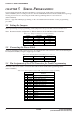
Fig. 4.1 Top view of the S5U1C8F360Z1 board
(1) IC socket
Insert an actual IC. Align Pin 1 with the bottom left corner of the socket (in top view) and insert IC.
(2) Connectors for target system (CN1, CN2, CN3)
These connectors are used to connect the I/O and LCD. Connect the target system using the I/O
cables (80-pin/40-pin × 2 flat type and 60-pin/30-pin × 2 flat type).
The pin assignment is the same as the S5U1C88816P connectors.
Refer to Chapter 6, "Connecting with the Target System", for the pin assignment.
(3) Connector for serial programming (CN4)
This connector is used to connect the On Board Programming Writer (S5U1C88000W3). Use this
connector when writing user data to the Flash EEPROM built into the microcomputer on the IC slot.
Refer to Chapter 5, "Serial Programming", for the pin assignment. For how to use the On Board
Programming Writer, refer to the "S1C8F360 Technical Manual".
(4) Power connector (CN5)
This connector is used to supply power to the S1C8F360 Adapter Board.
Use the supplied power cable for connection.
(5) Power system jumpers and check pins
Set according to the power supply conditions.
(6) Through holes for oscillator, LCD drive power and LCD voltage booster
Use them to mount the parts such as oscillator parts, capacitors and resistors. Refer to "Basic External
Wiring Diagram" in the "S1C8F360 Technical Manual" for the basic parts to be mounted.
(7) IC socket pattern
Cannot be used.
(5) (4)
(3)
(2)
(2)
(2)
(7)
(1)
(6)