
CMOS 8-BIT SINGLE CHIP MICROCOMPUTER Product Manual


CHAPTER 6: CONNECTING WITH THE TARGET SYSTEM
S5U1C8F360Z1 MANUAL EPSON 7
(ADAPTER BOARD FOR S1C8F360/8F361)
CHAPTER
6C
ONNECTING
WITH
THE
T
ARGET
S
YSTEM
The Adapter Board (S5U1C8F360Z1) can be used as an evaluation board by connecting it with the user
target board.
(1) To operate the microcomputer on the Adapter Board, the user must provide the peripheral circuits.
Refer to "Basic External Wiring Diagram" in the "S1C8F360 Technical Manual" for the required circuits.
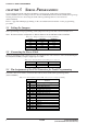
(2) Use the supplied I/O cables (80-pin/40-pin × 2 flat type and 60-pin/30-pin × 2 flat type) for connect-
ing between the S1C8F360 Adapter Board (S5U1C8F360Z1) and the target system.
(3) Be sure to turn the power off before connecting the target system because the I/O cable includes a
power line (V
DD).
CN1-1
(40 pins)
CN1-2
(40 pins)
I/O cables
To target board
CN2-1
(40 pins)
CN2-2
(40 pins)
CN3-1
(30 pins)
CN3
CN2
CN1
CN3-2
(30 pins)
mark
Fig. 6.1 Connecting with the target system