
CMOS 8-BIT SINGLE CHIP MICROCOMPUTER Product Manual


CHAPTER 2: PRECAUTIONS
2 EPSON S5U1C8F360Z1 MANUAL
(ADAPTER BOARD FOR S1C8F360/8F361)
CHAPTER 2PRECAUTIONS
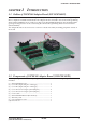
The connectors CN1, CN2 and CN3 have the same pin layout as the Peripheral Circuit Board for
S1C88816/8F360 (S5U1C88816P). This allows connection between the user target system for the
S5U1C88816P and the Adapter Board.
Take the following precautions when using the S1C8F360 Adapter Board (S5U1C8F360Z1):
2.1 Precautions for Operation
(1) Turn the power of all equipment off before connecting or disconnecting cables.
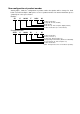
(2) Do not turn the power on while the input ports (K00–K03) are all set to low level. It may cause a
simultaneous key input reset.
2.2 Differences from the ICE88UR (S5U1C88000H5)
+ PRC88816 (S5U1C88816P)
The emulation system using the Adapter Board with an actual IC differs in terms of functionality and
characteristics from the S5U1C88816P emulation system, a fact which requires your attention. If these
differences are ignored, there is a possibility that your circuit will not operate properly on an actual IC
even though it might have performed well on the S5U1C88000H5 with the S5U1C88816P.
(1) Power supply differences
To operate the actual IC on the Adapter Board, an external power source voltage must be applied.
Refer to "Electrical Characteristics" chapter in the "S1C8F360 Technical Manual" for the supply
voltage.
(2) I/O differences
The output drive capability and pull up resistance are different.
The input setup time is different therefore, when a circuit requiring consideration of the input re-
sponse time, such as a key matrix, is used, the system and the software should be designed according
to the specifications for the actual IC.
(3) LCD differences
The output drive capability is different.
Since there will be differences with the actual IC even for the drive voltage, the system and the
software should be designed in order to adjust the characteristics.
(4) Analog comparator differences
The response time and characteristics of the analog comparator are different. Consequently, the
system and the software should be designed according to the specifications for the actual IC.
(5) Functional differences
<Oscillation circuit>
• The Adapter Board does not contain oscillator parts. Mount the parts according to the selected mask
option for the actual IC.
• The OSC3 oscillation stability time of the S5U1C88816P is shorter than that of the actual IC. There-
fore, the application program must take enough of interval (more than the oscillation stability time
in the actual IC) between starting the OSC3 oscillation and switching the system clock to OSC3.
• The logic level is different and it makes different oscillation timings such as the start and stop times.
•When switching the operating clock from OSC3 to OSC1, be sure to switch OSC3 oscillation off with
separate instructions. Using a single instruction to process simultaneously may cause a malfunction
of the CPU.