
Owner`s manual

Owner’s Manual
720005-0000
November 2009
16
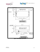
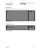
Communication Cables Pin-Out
The tables below detail the connection pin-out for the Universal Interface (14-pin Molex)
on the printer side.
Pin Signal Name Printer I/O Host I/O Printer Function
1 Reset Input Output Resets Printer
2 PRT_AUX_RXD Input Output Auxiliary Receive
3 V
AUX
Input Output Auxiliary Power
4 PRT_AUX_TXD Output Input Auxiliary Transmit
5 Signal Ground Signal Ground Signal Ground Signal Ground
6 24V Power Input n/a Power Input
7 Power Ground Power Ground n/a Power Ground
8 24V Power Input n/a Power Input
9 Bezel_pwm 24V Output n/a Bezel Driver
10 Power Ground Power Ground n/a Power Ground
11 PRT_RS232_RXD Input Output Data Receive
12 PRT_RS232_TXD Output Input Data Transmit
13 PRT_Status Output Input Pinter Ready
14 PRT_RS232_RTS Output Input Handshake
Table 10: 14-Pin Universal Interface Pin-Out
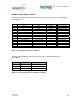
The tables below detail the connection pin-out for the front Bezel Connector
(3-pin Molex).
Pin Signal Printer I/O
1 Bezel PWM Output
2 24VDC Output
3 GND GND
Table 11: Pin-out and signals of Front Molex (for Bezel)