USER’S MANUAL P07303 Stand Alone VFD Pole Display 48200550 (January,2002 V1.
FCC Notice Federal Communications Commission (FCC) Radio Frequency Interference Statement This device complies with part 15 of the FCC Rules. Operation is subject to the following two conditions; (1) This device may not cause harmful interference, and (2) this device must accept any interference received, including interference that may cause undesired operation. COPYRIGHT & TRADMARK All rights reserved. The information contained in this guide has been validated and reviewed for accuracy.
Contents 1. Features....................................................................................................... 1 2. General Specification................................................................................... 2 3 Unpacking and Checking the Parts .............................................................. 3 4. Interface....................................................................................................... 4 4.1 Specifications .......................................
8.6 Page 3 (PC860: Portuguese) (80H – FFH)................................. 25 8.7 Page 4 (PC863: Canadian-French) (80H – FFH) ....................... 25 8.8 Page 5 (PC865: Nordic) (80H – FFH)......................................... 26 8.9 Page 6 (Slavonic) (80H – FFH)................................................... 26 8.10 Page 7 (Russia) (80H – FFH) ................................................... 27 9.Command details..................................................................................
1. Features (1) Data can be display on 20 columns x 2 lines. (2) Blue–green color and large character are easy to see (3)The DIP switches setting emulate commands mode, baud rate and international character. (4) Command emulation modes include POS7300/ CD5220 II/ ADM787/ UTC / AEDEX/ Epson/ DSP800. (5) User’s-defined character and message can be downloaded. (6) Display area can be controlled by window function. (7) Provides an interface based in RS-232C, and RS232C baud rate from 4800 to 38400 bps.
2.
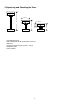
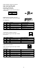
3 Unpacking and Checking the Parts G 501 mm 225 mm 191 mm 281 mm 93 mm •Pole Display Module •Flat Cable (DB-9P to DB-9P flat cable connector ) •Base Unit •Two pieces of pole support (1x22cm, 1x9cm) •Installation guide •Power Adapter 3
4. Interface 4.1 Specifications Data transmission: Synchronization: Handshaking: Signal level: Baud rates: Parity: Bit length: Stop bits: Serial Asynchronous DTR / DSR MARK = -3 to –15 V (logic “1”) SPACE = +3 to +15 V (logic “0”) 4800,9600,19200,38400 bps None, even 8 bits 1 or more 4.
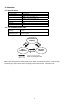
4.3. Interface 4.3.1 Stand alone VFD Pole Display Below illustrate the configuration of Stand alone VFD Pole Display base.
CN2: RS-232C connects to PC/Host CN3: Connect to display panel CN6: Power supply connector CN1,CN4, CN5: No used Power Supply Connectors CN6 / Connector type: DC jack (5.5/2.
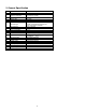
5. Dip Switch and Software Setting 5.1 Command type selection SW1 ON OFF ON OFF ON OFF ON OFF SW2 ON ON OFF OFF ON ON OFF OFF SW3 ON ON ON ON OFF OFF OFF OFF Command type POS7300 ESC/POS ADM 787 DSP800 AEDEX UTC/P UTC/S CD5220 5.2 Baud rate selection SW8 ON OFF ON OFF SW9 ON ON OFF OFF Baud rate (bps) 4800 9600 19200 38400 Default 5.3 Parity check selection SW10 ON OFF Parity check None-parity Even-parity Default 5.
5.5 International character set SW4 SW5 SW6 SW7 Character set Code table ( 80H-FFH) ON ON ON ON *default U.S.A. PC-437(USA, standard Europe) OFF ON OFF ON OFF ON OFF ON OFF ON OFF ON OFF ON OFF ON OFF OFF ON ON OFF OFF ON ON OFF OFF ON ON OFF OFF ON ON ON OFF OFF OFF OFF ON ON ON ON OFF OFF OFF OFF ON ON ON ON ON ON ON OFF OFF OFF OFF OFF OFF OFF OFF FRANCE PC-850(multilingual) GERMANY PC-850(multilingual) U.K.
5.7. Software Status Setting When system POWER ON, there is no need to turn off to modify Command Type, Baud Rate, Parity, Demo Mode and International Character. To re-set DIP Switch to various Command Type under the following list of Command to modify the setting. The setup value will stored in the EEPROM. When DIP Switch is OFF. Next time the system POWER ON previous setup value will be the default value and no need to modify. 5.7.1. Baud rate STX 05 B n ETX ASCII Format Dec. Format Hex.
N nternational font 30h .S.A. 31h RANCE 32h GERMANY 33h .K. 34h DENMARK I 35h WEDEN 36h TALY 37h PAIN n nternational font 38h APAN 39h ORWAY 3Ah DENMARK II 3Bh LAVONIC 3Ch RUSSIA 3Dh .S.A. 3Eh ot used 3Fh ser define pattern 5.7.3 Command type select STX 05 C n ETX ASCII Format Dec. Format Hex. Format Description N 30h 31h 32h 33h /Change command type/ STX 05 C n ETX [02][05][67] n [03] [02h][05h][43h] n [03h] 30h n 37h This command will change the command type and initialize the display.
5.7.4 Reset EEPROM STX 05 07 n ETX /Reset EEPROM/ ASCII Format STX 05 07 n ETX Dec. Format [02][05][07][n][03] Hex. Format [02h][05h][07h][n][03h] Description This command will reset the content of EEPROM (e.g. Demo scroll data, user-define character) N 31h 32h 33h Description Clear all EEPROM contents Clear upper line data message Clear lower line data message 5.7.5 Save data for demo display STX 05 L n m ETX /Save demo message to EEPROM/ ASCII Format STX 05 L n m ETX Dec.
5.7.7 Set Communication parity STX 05 P n ETX /Parity check selection/ ASCII Format STX 05 P n ETX Dec. Format [02][05][80] n [03] Hex. Format [02h][05h][50h] n [03h] n=30h,31h Description Change the display communication parity. Set 8 data bit and the parity set for even or non-parity. N 30h 31h Parity check None-parity Even-parity 5.7.8 Show VFD Firmware Version STX 05 V 01 ETX ASCII Format Dec. Format Hex.
6.
Table-2 FLYTECH PARTNER EPSON GIGA POS7300 CD5220 D101 UTC/S UTC/P AEDEX ADM788 DSP800 Upper line message scroll once pass O O Change attention code O O Two line display Clear upper line and move cursor to upper left-end position Clear bottom line and move cursor to bottom left-end position Set period to upper line, last n position O O Set line blinking, upper line O O O O O O Clear line blinking, upper line Clear field 1 and move cursor to field 1, first position Clear field 2 and move cursor t
7. Command 7.1. POS7300 series command set POS7300 Standard Mode Command List Command ESC F A .. CR ESC F B .. CR ESC F D .. CR ESC F O ..
7.2 CD5220 Standard Mode Command List Command ESC DC1 US SOH ESC DC2 US STX ESC DC3 US ETX ESC Q A .. CR Code (hex) 1B 11 1F 01 1B 12 1F 02 1B 13 1F 03 1B 51 41 [n]x20 0D ESC Q B .. CR 1B 51 42 [n]x20 0D ESC Q D ..
CD5220 Standard Mode Command List-2 Command ESC I x y US $ x y ESC @ ESC W s x1 x2 y Code (hex) 1B 6C x y / 1F 24 x y 1 x 20, y=1,2 1F 24 x y 1 x 20,y=1,2 1B 40 1B 57 1 x1 x2 y 1 x1 x2 20 y=1,2 CLR 0C CAN 18 ESC * n US X n ESC & s n m [a (P1…Pa)]x (m-n+1) ESC ? n 1B 2A n 1 n 4 1F 58 n 1 n 4 1B 26 1 n m [a(p1…pa)]x (m-n+1) 20 n m FF 1B 3F n n=20h~7Fh ESC % n 1B 25 n ESC _ n ESC f n 1B 5F n 1B 66 n ESC c n 1B 63 n ESC = n 1B 3D n n=01,02,03,31,32,33 ESC s 1 1B 73 01 ESC d 1 1B 64 01 n=00,0
*2: The parameter of international fonts set control by command “ESC f n” Parameter n ‘A’ ‘G’ ’I’ ‘J’ ‘U’ ‘F’ ‘S’ ‘N’ ‘W’ ‘D’ ‘E’ ‘L’ ‘R’ International Font Set U.S.A. Germany Italy Japan U.K. France Spain Norway Sweden Denmark I Denmark II Slavonic Russia *3: The parameter of the code table control by command “ESC c n” Parameter “n” International Font Set ‘A’ ‘J’ ‘L’ ‘R’ Compliance with ASCII code Compliance with JIS code Compliance with SLOVONIC code Compliance with RUSSIA code 7.
7.4 UTC enhanced mode command list Command ESC u A .. CR ESC u B .. CR ESC u D .. CR ESC u E .. CR ESC u F .. CR ESC u H .. CR ESC u I ..
7.
7.8 EPSON ESC/POS command list-1 Command HT BS US LF LF US CR CR HOM US B US $ x y CLR US X n US E n ESC @ ESC t n ESC R n US r n US MD1 US MD2 US MD3 ESC & s n m [a(p1..pa)]x m-n ESC ? n ESC % n CAN ESC # n US # n m US C n US . n US , n US ; n Code (hex) 09 08 1F 0A 0A 1F 0D 0D 0B 1F 42 1F 24 x y (x=1~20, y=01,02) 0C 1F 58 n (01 n 04) 1F 45 n (n=00~ffh) 1B 40 1B 74 n (n=00-0fh) 1B 52 n (n=00-0fh) 1F 72 n (n=00,01) 1F 01 1F 02 1F 03 1B 26 1 n m [a(p1..
EPSON Esc/pos command list-2 Command ESC W n s x1 y1 x2 y2 ESC = n US : Code (hex) 1 B 57 n s x1 y1 x2 y2 n=1,2,3,4 s=0,1 1B 3D n n=1,31,select printer n=2,32,select display n=3,33, select printer, display 1F 3A US ^ n m 1F 5E n m 00 (n, m) ff n=Word time m=show string time US @ US T h m US U ESC s 1 1F 40 1F 54 h m 0<=h<=17h, 0<=m<=3bh 1F 55 1B 73 01 ESC d 1 1B 64 01 Function description Specify/cancel the window range. 1<=x1<=x2<=20 1<=y1<=y2<=2 Select peripheral device.
8. Character Set 8.1 International Character Sets 8.
8.3 Page 0 (PC437: USA, Standard Europe) (80H – FFH) 8.4 Page 1 (Katakana) (80H – FFH) 8.
8.6 Page 3 (PC860: Portuguese) (80H – FFH) 8.
8.8 Page 5 (PC865: Nordic) (80H – FFH) 8.
8.
9.Command details 9.1 Overwrite mode In this mode, the cursor will move rightward and begin from the upper left-end position. When the cursor reached the end of the upper line, the cursor will move down to the bottom left-end position to continue. When the cursor reached the end of the bottom line, it will move up the upper left-end position and overwrite the previous characters. 9.2 Vertical scroll mode In this mode, the cursor will move rightward.
9.8 Move cursor up Move the cursor up one line. When the or is on the upper line, this command operates differently depending on the display mode. Overwrite mode: The cursor is moved to the same column the lower line. Vertical scroll mode: The characters display on the upper line is scrolled to the lower line, and the upper line is cleared. The cursor will remain at the same position. Horizontal scroll mode: The cursor will remain stationary. 9.9 Move cursor down Move the cursor down one line.
9.17 Clear display screen, and clear string mode All the display characters will be cleared, and the string mode will be cancelled. 9.18 Clear current line, and cancel string mode The current line is cleared, and the string mode is cancelled. 9.19 Brightness adjustment Adjust the brightness of the vacuum fluorescent display. When n=3,brightness=70% When n=4,brightness=100% 9.20 Set cursor ON or OFF When n=0, cursor is OFF When n=1, cursor is ON 9.
9.26 Character font format One font consists of 5 bytes’ string. The string format is: it yte 1 R7C1 R6C1 R5C1 R4C1 yte 2 R7C2 R6C2 R5C2 R4C2 yte 3 R7C3 R6C3 R5C3 R4C3 yte 4 R7C4 R6C4 R5C4 R4C4 yte 5 R7C5 R6C5 R5C5 R4C5 10.
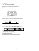
Appendix A: Display Module Dimension 200mm 0.38o 176mm 70mm 39mm 158.6mm 5.25mm 0.85mm 0.25mm 1.05mm 0.25mm 9.0mm 9.5mm 1.5mm 22.5mm 1.5mm 1.5mm 6.