
Service manual


PhotoPC 3100Z Revision A
Operating Principles Circuit 49
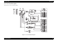
2.2.2.4 Lens Drive Block
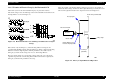
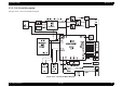
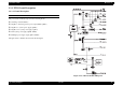
The figure below is the lens drive block diagram.
Figure 2-11. Lens Drive Circuit Block Diagram
IRIS AND SHUTTER DRIVE
The iris stepping motor drive signals (IIN1, IIN2, IIN3 and IIN4) which are output
from the ASIC expansion port (IC108) are used to drive by the motor driver (IC951),
and are then used to drive the iris steps. It can be increased iris steps by IENA control.
FOCUS DRIVE
The focus stepping motor drive signals (FIN1, FIN2, FIN3 and FIN4) which are output
from the ASIC expansion port (IC107) are used to drive by the motor driver (IC952).
Detection of the standard focusing positions is carried out by means of the photo
interrupter (PI) inside the lens block.
ZOOM DRIVE
The zoom stepping motor drive signals (ZIN1, ZIN2, ZIN3 and ZIN4) which are
output from the ASIC expansion port (IC107) are used to drive by the motor driver
(IC953). Detection of the standard zoom positions is carried out by means of photo
reflector (ZPI) inside the lens block.