
Service manual


PhotoPC 3100Z Revision A
Disassembly and Assembly Disassembly 69
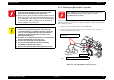
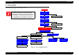
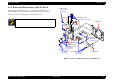
4.2.3 Removal of CA1/2 Board and Lens Assembly
The following is the discharging process of CA1 Board, CA2 Board and Lens
assembly. Disassembling procedure should follow numbers indicated in the figure
below.
The blue oblique letters in the figure show the tightening torque.
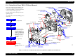
Figure 4-5. Removal of CA1, CA2 and Lens Assembly
A D J U S T M E N T
R E Q U I R E D
When replacing the CA1 board, CA2 board, or lens assembly,
perform the adjustment. (See Ch5.)
C A U T I O N
Never disassemble Optical assembly which must be
replaced by a unit.
Be careful at its direction when installing the optical filter
of the lens assembly. (See “Assembly” on page 71.)
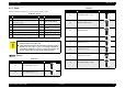
9. S-TP PAN PCS 1.7x5
0.18±0.02N·m
(1.8±0.2kg·cm)
1. S-TP PAN PCS 1.7x5
0.18±0.02N·m
(1.8±0.2kg·cm)
2. PAN PCS 1.7x4
0.18±0.02N·m
(1.8±0.2kg·cm)
3.S-TP PAN PCS 1.7x5
0.18±0.02N·m
(1.8±0.2kg·cm)
11. S-TPG PAN PCS 1.7x6
0.20±0.25N·m
(2.0±2.5kg·cm)
10. PAN PCS 1.7x2.5
0.15±0.20N·m
(1.5±2.0kg·cm)
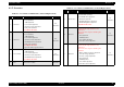
L
e
n
s
A
s
s
e
m
b
l
y
Optical assembly
6. FPC
Optical Filter
12. CA1 board
8. CA2 board
7. Connector
4. Connector
5. Holder
Speaker