EPSON Programming Guide For 6 Color EPSON Stylus Pro 7000 (PM-7000C) (Level I) EPSON Imaging Technology Center Revision: 1 (Date: 6/20/00) Page: 1
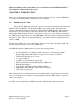
All Rights Reserved. This publication may only be used for the purposes of research and development of products and services enhancing, enabling, or facilitating existing and future products and services bearing the EPSON trademark, and for providing support to those engaging or intending to engage in such activities. All other uses are unauthorized.
TABLE OF CONTENTS: CHAPTER 1: INTRODUCTION ............................................................................................................. 6 1.1 EPSON Stylus Pro 7000 ............................................................................................................................................... 6 CHAPTER 2: PAPER TYPES AND SIZES .................................................................................... 9 2.1 EPSON Paper Types and Sizes for the Stylus Pro 7000......
6.9 Set Resolution of Raster image “ESC (D nL nH rL rH v h”..................................................................................... 32 6.10 Set Absolute Vertical Print Position “ESC (V nL nH m1 m2 m3 m4 ”.............................................................. 34 6.11 Set Relative Vertical Print Position “ESC (v nL nH m1 m2 m3 m4”.................................................................. 35 6.12 Set Absolute Horizontal Print Position “ESC ( $ nL nH m1 m2 m3 m4”.............
LIST OF TABLES: Table 1: The EPSON Stylus Pro 7000 Printer Feature Summary...................................................................... 7 Table 2: Stylus Pro 7000 Throughput.................................................................................................................. 8 Table 3: EPSON Paper Types and Sizes for Stylus Pro 7000 ............................................................................. 9 Table 4: Characteristic Information for Each Paper Type – ROLL Paper .......
This Programming Guide is intended for use in conjunction with the EPSON Standard ESC/P Reference Manual (December 1997) CHAPTER 1: INTRODUCTION This section of the Programming Guide will provide a technical overview of another EPSON’s 6color large format inkjet printer to facilitate driver development. 1.1 EPSON Stylus Pro 7000 The Stylus Pro 7000 is the follow-up to the six-color large format inkjet printer Stylus Pro 9000 introduced by EPSON.
Table 1: The EPSON Stylus Pro 7000 Printer Feature Summary EPSON Stylus Pro 7000 Print Head 64 black nozzles, 320 color nozzles, 64 nozzles x 3 (CMYLcLm). Same head as Stylus Pro 5000. Interface (s) Parallel, USB and Optional Ethernet Printer ESC/P Raster & Language Remote Mode Resolution 1440(h) x 720(v) Max (dpi) Selectable dot Yes size Ink Type **CMYKLcLm Paper type vs.
Table 2: Stylus Pro 7000 Throughput Throughput A1 Print Time Resolution Print Mode 5 Min.
CHAPTER 2: PAPER TYPES AND SIZES 2.1 EPSON Paper Types and Sizes for the Stylus Pro 7000 In addition to the standard plain paper, EPSON provides special paper type in the following sizes: Table 3: EPSON Paper Types and Sizes for Stylus Pro 7000 Stylus Pro 7000 Paper Type/ Subset Plain Paper (Cut sheet) Letter √ US B √ US C √ US D √ A4 √ A3 √ A3+/Super A3/B √ A2 √ A1+ √ A1 √ B5 √ B4 √ B3 √ B2 √ Roll Paper √ (Thickness: 0.1) User-defined √ Paper Size in “inch” Paper Size in “mm” Product Code Number (U.
Table 3: EPSON Paper Types and Sizes for Stylus Pro 7000 - Cont’d Stylus Pro 7000 Paper Type/ Subset Paper Size in “inch” Paper Size in “mm” Product Code Number (U.S.) *EPSON SEMI GLOSS PAPER – HEAVY WEIGHT (Roll) (Thickness: 0.2mm) 24”x82’ 604mm x 25m SEMI GLOSS √ PAPER - HEAVY WEIGHT *EPSON GLOSSY PAPER – HEAVY WEIGHT (Roll) (Thickness: 0.2mm) GLOSSY PAPER 24”x67.9’ 604mm x 20.7m √ GLOSSY PAPER 12.95”x32.81’ 329mm x 10m √ GLOSSY PAPER 8.27”x32.
* These names are for U.S. market only. The Worldwide names for these media “Semigloss Photo Paper- Heavy Weight (Roll)” and “Glossy Photo Paper- Heavy Weight (Roll)” respectively. **The surface of Poster Board – Semigloss is same as Semi Gloss Paper-Heavy Weight. Therefore, with the Poster Board media the “Semi Gloss Paper- Heavy Weight” print mode is used. Note: For Roll Paper - The left, right, top and bottom margins of the Stylus Pro 7000 is 3mm, (42 dots).
2.2 Paper Type subject to Path & Page Delay, Cutter Auto OFF Paper Type Auto Cutter OFF Plain Paper Path Delay Page Delay ms S 0 0 Presentation Matte Paper 0 0 - Glossy Paper-Heavy Weight 0 0 - Semi Gloss Paper-Heavy Weight Photo Quality Ink Jet Paper 0 0 - 0 0 - Photo Paper 0 0 - Photo Quality Glossy Film 0 0 - Poster Board -Semigloss 0 0 OFF - Note: If Cut Sheet is selected, Auto Cutter ON can’t be selected. 2.
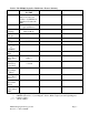
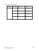
2.4 Characteristic Information for Each Paper Type Mechanism sequence setting, cutter On/Off information, drying time, and paper thickness are following as characteristic information (TBD) Table 4: Characteristic Information for Each Paper Type – ROLL Paper Paper type 1.1.1. Set mechanism sequence SN 03H 00H 00H 01H Plain Paper 00H (Default) Matte Paper 00H (Default) Photo Quality Glossy Paper 00H (Default) Photo Quality Semi Glossy Paper 00H (Default) Glossy Film 00H (Default) 1.1.3.
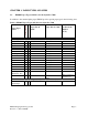
CHAPTER 3: PRINTABLE AREAS 3.1 Printable Area – Stylus Pro 7000 Roll Paper d a b c d e a b c e f f Table 6: Printable Area for the EPSON Stylus Pro 7000 – Roll Paper Paper type a b c d “Units are in dots where 1 dot = 1/360” Letter US B US C US D A4 A3 Super A3/B A2 A1 B5 B4 B3 B2 User Defined Left Margin 42 42 42 42 42 42 42 42 42 42 42 42 42 42 EPSON Imaging Technology Center Revision: 1 (Date: 6/20/00) Printable Width 2976 3876 6036 7836 2892 4125 4579 5869 8335 2496 3559 5075 7215 Min.
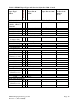
3.2 Printable Area – Stylus Pro 7000 Cut Sheet Paper d a b c d e a b c e f f Table 7: Printable Area for the EPSON Stylus Pro 7000 – Cut Sheet Paper type a b c d “Units are in dots where 1 dot = 1/360” Letter US B US C US D A4 A3 Super A3/B A2 A1 B5 B4 B3 B2 User Defined e f Left Margin Printable Width Right Margin Top Margin Printable Height Bottom Margin/ 42 42 42 42 42 42 42 42 42 42 42 42 42 42 2976 3876 6036 7836 2892 4125 4579 5869 8335 2496 3559 5075 7215 Min. 2496Max.
Notes: Left and top Margins: 42 dots (3mm) for both roll paper and cut sheet. Bottom Margin; 42 dots for roll paper, 198 dots (14mm) for cut sheet. (Unit: 360 dpi) The maximum printing width is 604mm. (= 24 inch - 3 mm- 3 mm) The Minimum and Maximum Printing Width for the Roll Paper is 176mm~604mm. The Maximum Printing Height for the Roll Paper is 25m. The Minimum and Maximum Printing Width for the Cut Sheet paper is 176mm~604mm.
CHAPTER 4: Printing Mode 4.1 Printing Mode – Stylus Pro 7000 Following table shows ink duty and printing mode for each Media type, Resolution, MicroWeave, Dot Control and Bi-directional ( High Speed) for the EPSON Stylus Pro 7000. These printing modes use the printer MicroWeave. If you do not use the printer MicroWeave, then the command parameters are different.
Table 9: Recommended Printer Driver Settings for the EPSON Stylus Pro 7000 Media Media Type Printer Driver Mode Plain Paper Plain Paper Presentation Matte Paper Presentation Matte Paper *GLOSSY PAPER-HEAVY WEIGHT Photo Paper *SEMI GLOSS PAPER- HEAVY WEIGHT Semi Gloss Photo Paper Poster Board-Semigloss Semigloss Photo Paper Glossy Film Roll Glossy Film Photo Glossy Paper Photo Quality Glossy Film Backlight Film Photo Quality Glossy Film These names are for U.S. market only.
CHAPTER 5: COMMAND SEQUENCE FLOW 5.1 Raster Graphics Mode The Raster graphics command controls the following two modes. 1) Non-compressed mode Print data are transferred without compression. This is effective especially for photographs and other data, which yield only a low compression ratio. 2) RLL compression mode Print data are compressed using RLL (run-length limited) compression. This is effective for data with repeated patterns, such as graphics and illustrations.
5.2 Command Transfer Sequence The basic commands and command sequence for use with non-compressed mode and RLL compression mode are shown below. Command setting procedure for Non compression mode and Run-length compression mode Table 11: Command sequence flow Forward Setting cycle Document Unit Page Unit Raster Unit 1.Initial Setting Items 1.1 Set remote mode 1.1.1 Set Mechanisim Seq. 1.1.2 Set paper path 1.1.3 Set auto cutting state 1.1.4 Set no paper feed eject 1.1.5 Set drying time 1.1.
“ESC ( R” is an ESC/P2 command to enter the EPSON REMOTE Mode. While in this mode, no ESC/P or ESP/P 2 commands will be recognized by the printer until the “ESC 00H” command is invoked to exit Remote Mode. See the Remote mode section for more information. ESC (/, ESC($ (Set horizontal position command) is recommended to shift to left margin. (To standardize specification: Command to shift left margin has no CR command.
CHAPTER 6: INDIVIDUAL COMMAND SPECIFICATION 6.1 Initialize Printer “ESC @” Format: ASCII Hex Decimal ESC 1B 27 @ 40 64 Function: - - The various settings are returned to their initial values. The function of the CAN command is executed. The page management coordinate system and the position management coordinate system are set by taking the origin upon the Y-axis as the present printing position on the Y-axis. The present printing position on the X-axis is set to the origin upon the X-axis.
6.2 Select Graphics Mode “ESC (G nL nH m” Format: ASCII Hex Decimal ESC 1B 27 ( 28 40 G 47 71 nL nL nL nH nH nH m m m Range of Definition: nL=01H, nH=00H m=01H or 31H Function: - Shifts to graphics mode. - If m has any value other than the above, this command is ignored. - Printing of lines up to the present line is started, and the printer waits until the printing is completed. - The various settings are the same as when the power is turned on.
6.3 Set Unit “ESC (U nL nH p v h mL mH” Format: ASCII Hex Decimal ESC 1B 27 ( 28 40 U 55 85 nL nL nL nH nH nH p p p v v v h h h mL mL mL mH mH mH Range of Definition: nL=05H, nH=00H p=01H, 02H, 04H, 08H v=01H, 02H, 04H, 08H h=01H, 02H, 04H, 08H mL=A0H, mH=05H Function: - - Set the following standard units in units of P/(mH*256+mL) inch. Page units ESC (c, ESC (C, ESC (S, etc. Set the following standard units in units of V/(mH*256+mL) inch. Vertical position units ESC (v, ESC (V, etc.
The units for the “unit” unit page length specification by the ESC (C command is set. The units for the page format specification by the ESC (c command is set. The units for the paper dimension specification by the ESC (S command is set. Commands related in the direction of an effect (Operation) The initial state is returned to by the ESC @ command.
6.4 Turn Unidirectional Mode On/Off “ESC U n” Format: ASCII Hex Decimal ESC 1B 27 U 55 85 n n n Range of Definition: n=00H, 01H, 02H, 30H, 31H, 32H Function: - The printing direction is selected according to the value of n in the following manner: n=00H or 30H: selects Bi-directional printing n=01H or 31H: selects Unidirectional printing n=02H or 32H: selects automatic printing direction control - If n has any value other than the above, this command is ignored.
6.
6.6 Select Dot Size “ESC ( e nL nH m d” Format: ASCII Hex Decimal ESC 1B 27 ( 28 40 e 65 101 nL 02 02 nH 00 00 m m m d d d Range of Definition: nL = 02H, nH= 00H m = 00H, d = 00H, 01H, 02H, 03H, 04H Function: - The value of d specifies the Dot Size. d 00H: 01H: dot size 1 02H: dot size 2 03H: dot size 3 Dot Size Default* Micro dot Normal dot (Single) Normal x 2 (Double) * Dot selection Normal (Single or Double) is performed automatically depending upon the chosen resolution.
6.7 Set Page Format “ESC (c nL nH t1 t2 t3 t4 b1 b2 b3 b4” Format: ASCII Hex Decimal ESC 1B 27 ( 28 40 c 63 99 nL nL nL nH nH nH t1…… t4 t1…… t4 t1…… t4 b1…... b4 b1…... b4 b1…...
- - - Commands related in the direction of applying an effect (Setting) The set page length is changed by the ESC (C commands. Commands related in the direction of receiving an affect (Setting) The top margin and the bottom margin are set by the ESC ( C command. The page length and the bottom margin position are returned to their initial states by the ESC @ and the ESC (G commands.
6.8 Set Paper Size “ ESC (S nL nH w1 w2 w3 w4 l1 l2 l3 l4” Format: ASCII ESC Hex 1B Dec. 27 ( 28 40 S 53 83 nL nL nL nH nH nH w1.. w1.. w1.. w4 w4 w4 l1 l1 l1 l2 l2 l2 l3 l3 l3 l4 l4 l4 Range of Definition: nL=08H, nH=00H Function: - Set (w4x256x256x256+w3x256x256+w2x256+w1) x (Page Control Units) inches as the X direction paper width (actual width from the left to the right).
6.9 Set Resolution of Raster image “ESC (D nL nH rL rH v h” Format: ASCII HEX Decimal ESC 1B 27 ( 28 40 D 44 68 nL nL nL nH nH nH rL rL rL rH rH rH v v v h h h Range of Definition: nL=04H, nH=00H 0 < v ≤127 0 < h ≤127 Function: - Set resolution of raster image at (rHx256+rL)DPI. Set raster vertical direction resolution at v/(rH x 256 + rL) DPI Set raster horizontal direction resolution at h/(rH x 256 + rL) DPI This command is effective only for the graphic mode.
Related Command: Commands related in the direction of applying an effect (Setting) Effect to be processed by ESC i command. Command related in the direction of receiving an effect (Setting) The Resolution setting of Raster image is returned to this initial states by the ESC @ and the ESC (G commands.
6.
6.
6.
Format: ASCII HEX Decimal ESC 1B 27 ( 28 40 / 2F 47 nL nL nL nH nH nH m1 m1 m1 m2 m2 m2 m3 m3 m3 m4 m4 m4 Range of Definition: nL=04H, nH=00H 0 <= (m4x256x256x256 +m3x256x256 + m2x256 + m1)) x (relative horizontal print position set unit) inch <= 1FFFFFFFH/1440 inch, or If bit 7 of m4 is 1, this means that a negative value has been set.
6.14 Select Raster Graphics Data “ ESC i r c b nL nH mL mH d1…dk “ Format: ASCII HEX Decimal ESC 1B 27 i 69 105 r r r c c c b b b nL nL nL nH nH nH mL mL mL mH mH mH d1..dk d1..dk d1..dk Range of Definition: r = 00H, 01H, 02H, 04H, 11H, 12H c = 00H, 01H b = 01H, 02H 0 <= ( nHx256 + nL ) <= 7FFFH 0 <= ( mHx256 + mL ) <= 7FFFH Function: - Select a color for the raster according to the “r” value.
- If the printing position is set by this command to a non-printable region (right margin), the printing position in the X direction is reset to the right margin position The printing position in the Y direction is not changed by this command. If the image data is set to a non-printable region, the data is ignored. This command is effective only for the graphic mode.
6.15 New Page (Form Feed) “FF” Format: ASCII Hex Decimal Parameters Range: FF 0C 12 - Function: - - The contents of the print buffer are printed, the position management coordinate system is set to the next page, and the printing position is set to the origin on this new position management coordinate system. The paper is output. With single sheet paper, this command is ignored if no paper is input.
6.16 Enter Remote Mode Command “ ESC (R ” Format: ASCII ESC Hex 1B Dec 27 ( 28 40 R 52 82 08H 08 08 00H 00 00 00H 00 00 REMOTE1 52 45 4D 4F 54 45 31 82 69 77 79 84 69 49 Function: - This command is used to enter Remote Mode from ESC/P or ESC/P 2 mode. Exits current printer controls language and enters Remote Mode. This mode is maintained until the Exit Remote Mode command “ESC 00 00 00” is accepted by the printer. - This command is only valid in text mode.
6.17 Select Mechanism Sequence “SN” The printer driver can control the head gap by this SN command. Format: ASCII Hex Dec S 53 83 N 4E 78 03H 03 03 00H 00 00 00H 00 00 m1 m1 m1 m2 m2 m2 Parameters: The following m1 and m2 parameters are each one byte binary values that indicates mechanism sequences.
6.18 Set Paper Path ”PP” 03H 00H 00H m1 m2 Format: “PP” 03H 00H 00H m1 m2 Parameters: The parameter m1 is one byte binary value, and indicates the paper path: Paper Manual feed Roll paper Reserved m1 02H 03H 04H - FFH The parameter m2 is one byte binary parameter, and indicates the paper path Number. This has no meaning with Stylus Pro 7000 Function - - The paper path default environment is set.
6.19 Set Auto Cutting State “ AC” 02H 00H 00H m1 Format: “AC” 02H 00H 00H m1 Parameters: Parameter m1 is a one byte binary value, and indicates the state as follows: Set Auto Cutting Auto Cutting Off Auto Cutting On Horizontal print page line On Blank skip eject mode reset Blank skip eject mode set Reserved m1 00H 01H 02H 40H 41H 03H - FFH Function: - The default environment roll paper auto cutting state is set.
6.20 Set Drying Time “DR” 04H 00H 00H m1 m2 m3 Format: “DR” 04H 00H 00H m1 m2 m3 Parameters: The m1, m2 and m3 are each one byte binary parameters. Parameter m1 indicates the state as follows: Drying Position Per scan Per page Reserved m1 00H 01H 02H - FFH The drying time by the following expression is set by the parameters m2 and m3. If m1=00H(drying per scan), the unit of time is m second. If m1=01H(drying per page), the unit of time is seconds.
6.21 Select Ink Type “IK” 02H 00H 00H m1 Format: “IK” 02H 00H 00H m1 Parameters: Parameter m1 is one byte binary parameter, and indicates the ink type as follows: Ink Type Dye ink Pigment ink Reserved m1 00H (N/A) 02H - FFH Function: - The default environment ink type is set. If parameter m1 is out of range, this command is ignored and the existing setting is maintained. This command is only valid in remote mode.
6.22 Set Pause After Printing “PZ” 02H 00H 00H m1 Format: “PZ” 02H 00H 00H m1 Parameters: Parameter m1 is one byte binary code, and indicates the state as follows: Set Pause After Printing Off On Reserved m1 00H 01H 02H - FFH Function: - The default pause state after printing is set. If the pause after printing is ON, the printer is stopped at the pause state after the FF command is executed. If the auto cutting is set, it is pausing after cutting / printing horizontal lines.
6.23 Set Vertical Print Page Line Mode “EX” 06H 00H 00H 00H 00H 00H 14H m1 Format: “EX” 06H 00H 00H 00H 00H 00H 14H m1 Parameters: Parameter m1 is one byte binary code, and indicates the state as follows: Set Vertical Print Page Line Mode Off On Reserved m1 00H 01H 02H - FFH Function: - - The default environment vertical print page line mode is set.
6.24 Select Paper Thickness “PH” 02H 00H 00H m1 Format: “PH” 02H 00H 00H m1 Parameters: Parameter m1 is one byte binary code, and indicates the state as follows: Select Paper Thickness Thickness 0.0 mm Thickness 0.1 mm Thickness 0.2 mm Thickness 0.3 mm Thickness 0.4 mm Thickness 0.5 mm Thickness 0.6 mm Thickness 0.7 mm Thickness 0.8 mm Thickness 0.9 mm Thickness 1.0 mm Thickness 1.1 mm Thickness 1.2 mm Thickness 1.3 mm Thickness 1.4 mm Thickness 1.5 mm Thickness 1.
6.25 Terminate Remote Mode “ ESC 00H 00H 00H ” Format: ESC 00H 00H 00H Function: - The following procedures are executed: The default environment is copied to the current environment. If interface related items have been changed, the interface related state and settings are changed. Software initialization is executed (If in ESC/P mode, initialization by ESC @. In other printer languages, initialization corresponding to ESC @.
6.26 Load Default Value “LD 00H 00H” Format: LD 00H 00H Function: - - - The following procedures are executed: The power on default environment memorized in NVRAM is loaded to default environment. NVRAM indicates EEPROM, DIP-SW, and ROM. The power on default environment is read from the appointed NVRAM with each setting item, and the default environment is loaded. However, settings by following commands are not changed by this command.
6.27 Paper Size Specification The region on the paper is separated for 2 regions, the printable region and the nonprintable region. These regions are defined as following; The printable region is the region that can be set for the printing position, and the region surrounded by the left margin position setting, the right margin position setting, the top margin position setting, and the bottom margin position setting.
The origin of the Y-axis is the top end of the paper for the page 1 just after feeding paper. The origin of the Y-axis after the page two is the position added page length to the origin of the page management coordinate system in the last page. In the case of cutting sheet, the top of the paper is the origin all the time, because only 1 page can be set. The page and the page length are defined as following; The page is the Y direction unit region including one printable region in it.
CHAPTER 7: SUPPLEMENT 7.1 Set Panel and Remote Command This printer has a display operation panel, and each setting can be set by the panel or by the remote commands. The following are the setting by the panel and by the remote commands: - The setting by the panel is saved as the default value of the printer. - The setting value of remote commands is used for items to set by the driver with remote commands. - The default value of the printer is used for items not to set by the driver.
The function to print page line of paper size position on the right side and at the bottom of the paper. - If the sheet is selected, the selection of the print page line is invalid. - The operation depends on the combination of auto cut On/Off. (See last paragraph) - The default setting of the print page line is Off. - The function is available only for printer MicroWeave Mode. 7.