RC170 Option Operator Panel OP1 Rev.
RC170 Option Operator Panel OP1 Rev.
RC170 Option Operator Panel OP1 Rev.1a Copyright © 2006 SEIKO EPSON CORPORATION. All rights reserved. OP1 Rev.
FOREWORD Thank you for purchasing our robot products. This manual contains the information necessary for the correct use of the Operator Panel. Please carefully read this manual and other related manuals before installing the robot system. Keep this manual handy for easy access at all times.
TRADEMARKS Microsoft, Windows, and Windows logo are either registered trademarks or trademarks of Microsoft Corporation in the United States and/or other countries. Other brand and product names are trademarks or registered trademarks of the respective holders. TRADEMARK NOTATION IN THIS MANUAL Microsoft® Windows® XP Operating system Microsoft® Windows® 2000 Operating system Throughout this manual, Windows XP, and Windows 2000 refer to above respective operating systems.
MANUFACTURER & SUPPLIER Japan & Others SEIKO EPSON CORPORATION Suwa Minami Plant Factory Automation Systems Dept. 1010 Fujimi, Fujimi-machi, Suwa-gun, Nagano, 399-0295 JAPAN TEL : +81-(0)266-61-1802 FAX : +81-(0)266-61-1846 SUPPLIERS North & South America EPSON AMERICA, INC. Factory Automation/Robotics 18300 Central Avenue Carson, CA 90746 TEL : +1-562-290-5900 FAX : +1-562-290-5999 E-MAIL : info@robots.epson.com Europe EPSON DEUTSCHLAND GmbH Factory Automation Division Otto-Hahn-Str.
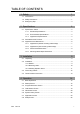
TABLE OF CONTENTS 1. Safety 1 1.1 Conventions...................................................................................................1 1.2 Safety Precautions ........................................................................................1 1.3 Emergency Stop ............................................................................................3 2. Specifications 2.1 4 Specification Tables .....................................................................................
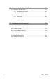
5. Programming for Operator Panel 5.1 5.2 27 Display on Operator Panel..........................................................................27 5.1.1 Simple Display Program.................................................................27 5.1.2 Display Device................................................................................28 Data Input from Operator Panel..................................................................28 5.2.1 Value Input...........................................
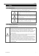
1. Safety 1. Safety 1.1 Conventions Important safety considerations are indicated throughout the manual by the following symbols. Be sure to read the descriptions shown with each symbol. WARNING This symbol indicates that a danger of possible serious injury or death exists if the associated instructions are not followed properly. WARNING This symbol indicates that a danger of possible harm to people caused by electric shock exists if the associated instructions are not followed properly.
1. Safety Only authorized personnel who have taken the safety training should be allowed to maintain the robot system. The safety training is the program for industrial robot operator that follows the laws and regulations of each nation. The personnel who have taken the safety training acquire knowledge of industrial robots (operations, teaching, etc.), knowledge of inspections, and knowledge of related rules/regulations.
1. Safety 1.3 Emergency Stop Immediately press the EMERGENCY STOP switch whenever you suspect any WARNING danger. The Operator Panel is equipped with an EMERGENCY STOP switch. Before operating the Operator Panel, make sure that the EMERGENCY STOP switch on the Operator Panel functions properly.
2. Specifications 2. Specifications 2.1 Specification Tables 2.1.1 Electrical Specifications Item Rated voltage Voltage range Power consumption Dielectric strength Insulation resistance Specifications DC 24 V DC 21.6 to 26.4 V 7 W or less AC 500 V 20 mA per minute (across charger and FG terminals) 500 VDC 20 MΩ or more (across charger and FG terminals) 2.1.
2. Specifications 2.2 Part Names and Functions (2) (3) (1) (9) (5) (4) (10) (8) (6) (7) (8) (1) Touch Panel This screen displays various information, and is used for automatic operation, data entry, WARNING and other operations. When the backlight of the touch panel goes out, the screen turns completely black and you can no longer see what is on the screen. The touch switches, however, are enabled.
2. Specifications (4) Power Lamp This lights (green) when the controller's power switch is turned ON. (5) Teach Pendant connector (Bypass Plug) This connector is for connecting the optional Teach Pendant for Robot Controller RC170. When the Teach Pendant does not need to be connected, connect the Bypass Plug. The robot status will be the Emergency Stop state unless the Teach Pendant or Bypass Plug is WARNING connected.
2. Specifications 2.3 Appearance and Dimensions 2.3.1 Appearance (without mounting metal hasps) [Unit : mm] 215 155 87 7 55 58 6 26 5 46 41 2.3.2 External appearance (with mounting metal hasps) [Unit : mm] 5 15 25 OP1 Rev.
2. Specifications 2.3.3 Panel Cutout Dimensions [Unit : mm] 4-R3 or less 201.5 141.5 2.3.4 Mounting Metal Hasps Dimensions [Unit : mm] 25 3.3 12.5 11 5 M4 Screw θ 32.5 8 17 0 3.6 −0.5 M4 Burring Ø4.1 OP1 Rev.
3. Installation 3. Installation 3.1 Unpacking OP1 1 unit Mounting metal hasp 4 units Connection cable (3 m) 1 unit Bypass Plug (install on body) 1 unit 3.2 Installation 3.2.1 Gasket Applicable model: ST400-WP01 Even in environment that do not require drip-proof, be sure to use the gasket (accessory provided with OP1). Install the Operator Pendant on a flat, level surface with the display facing down, and attach the gasket (provided) into the front bevelled groove from the rear.
3. Installation 3.2.2 Mounting Holes Refer to 2.3.3 Panel Cutout Dimensions for machining the mounting parts. - Prepare the gasket and mounting metal hasps to install the Operator Panel. - To ensure drip-proof performance, install the Operator Panel on a flat surface free of warping, scratches and unevenness. Attaching a stiffening plate is effective to prevent warping. - The panel thickness range should be from 1.6 to 5.0 mm. Choose a panel thickness taking the strength of the panel into consideration.
3. Installation - The Operator Panel is designed for vertical installation. It can also be installed at an angle. However, in this case, limit the angle of tilt from the vertical within 30 deg. Within 30deg. - If the Operator Panel is installed at an angle of tilt exceeding 30 deg, take measures, such as forced air cooling, to prevent the operating ambient temperature from exceeding 40 degC. - Do not install the Operator Panel horizontally. 3.2.
3. Installation (4) Secure the screws of the mounting metal hasps. Tighten the four screws slowly, in an even, crisscross pattern. Overtightening the screws may damage the Operator Panel. To ensure drip-proof performance, the appropriate tightening torque is 0.5 Nm. 3.3 Connecting Cables Be sure to connect the cables between the Controller and the Operator Panel WARNING properly. Do not allow unnecessary strain on the cables. (Do not put heavy objects on the cables.
3. Installation 3.4 Teach Pendant Connection (1) Disconnect the Bypass Plug connected to the Operator Panel. (2) Connect the connector of the Teach Pendant to the Operator Panel and secure it tightly. NOTE ) Make sure to screw in the connector tightly to ensure dust-proof and drip-proof performance. (3) Make sure that the Teach Pendant starts up. (4) Make sure that the EMERGENCY STOP switch of the Teach Pendant operates. NOTE ) NOTE ) OP1 Rev.
4. Operation 4. Operation 4.1 Basic Operations The Operator Panel is provided with five screens corresponding to specific functions. The Operator Panel can be switched to each of these screens at any time. (1) Program Execution screen (2) Task Monitor screen (3) I/O Monitor screen (4) System History screen (5) Application screen (1) Program Execution screen This screen displays various robot states (e.g. Emergency Stop, Safety Door, etc.).
4. Operation Buttons for moving to each of these screens are displayed on the left side of the screen. You can move to the desired screen at any time by pressing these buttons. Operator Panel screen image When the operator is prompted to confirm or perform an operation, the button for the respective screen on the left of the Operator Panel blinks. When a button blinks, touch the button to display the target screen, and perform the required operation (e.g. confirmation of display data or data input). 4.
4. Operation 4.3 Program Execution Screen Program Execution screen (when operations from the Operator Panel are not available) (1) Mode (2) Emergency Stop state (6) Serious Error state (3) Safetyguard state (7) Error state (4) Motor energization state (8) Warning state (5) Manipulator home state (9) Program number. (10) Start (11) Pause (12) Ready The program execution screen is for confirming Robot or Controller states, and for selecting and executing programs.
4. Operation (6) Serious Error state This turns ON ( display) when a major error has occurred that cannot be recovered by the reset button. When a serious error has occurred, the robot cannot perform tasks normally. Error details can be confirmed in the system history screen. To cancel the error, remove the cause of the error, and turn the Controller OFF then back ON again. (7) Error state This turns ON ( display) when an error has occurred.
4. Operation If the Operator Panel is set as a control device, buttons for executing and stopping programs are displayed on the Program Execution screen to enable these operations. Program Execution screen (when operations from the Operator Panel are available) (13) Select program No (17) Reset (14) Execute program (15) Pause program (16) Cancel program (13) Select program No. This button is for selecting the number of the program to execute.
4. Operation 4.4 Task Monitor Screen The Task Monitor screen allows you to monitor the states of each task. By confirming the current state of each task, you can gain hints as to which signal the robot is waiting for (i.e. why the robot has stopped when it has stopped due to an interlock or signal standby). You can select between a screen that displays all 16 tasks and a screen that displays eight tasks at a time. In the 16-task display screen, you can confirm the state of each task and line number.
4. Operation The display is refreshed every 0.5 seconds. Lines having a short processing time may not be displayed, or the same line number is visible all the time even if operations are actually being performed normally. This, however, is not a malfunction. The following task states are displayed: Run The task is being executed. Wait The task is standing for a sensor or a timer. Halt The task has halted. Pause The task indicates that the robot motion is paused.
4. Operation I/O Monitor screen (8-bit display) “*” (asterisk) is displayed before the signal for remote setting to separate remote setting and I/O label. In the 32-bit display, you can touch the currently displayed I/O column and temporarily confirm the I/O label in the popup window. The popup window disappears by touching. Touching the “INPUT”, “OUTPUT” or “MEMORY” area displayed at the top left of the screen successively switches the display in the following order: I/O input → I/O output → memory I/O.
4. Operation 4.6 System History Screen A system history (errors, warnings, and events) containing up to 5000 records is saved on the RC170 Controller. In the System History screen, you can display the past system history that is saved to the Controller. System History screen Summary of the error, warning or event. Each page of the System History displays a summary of five system histories.
4. Operation 4.7 Application Screen The Application screen provides the robot application programs and operator interface. The application program can be displayed on this screen by executing the Print command in the application program. Data can be input from this screen by executing the Input command in the application program. The Application screen provides a 1-page display area made up of 32 characters in the horizontal direction and 10 lines in the vertical direction.
4. Operation The last line of the display is the input area. When the Input command is executed in the application program, the input area is displayed at the last line of the screen. Application screen (numerical value input) In the case of numerical value input, touch the input area. This displays the numerical value input dialog box. Use this dialog box to input numerical values, and press the button to fix the input values.
4. Operation 4.8 Setup Screen If the bottom right of the screen (operator firmware version display area) is touched while the Startup screen is displayed, the screen for setting up the Operator Panel appears. When you finished the setup, touch the button at the bottom right of the screen. To cancel the setup and display the original state, touch the button at the bottom left of the screen. Startup screen Setup screen Language This item switches the display language for each of the screens.
4. Operation Change display after program execution Set whether or not to automatically switch the screen to the Application screen after an application has been started or program has been executed in the Program Execution screen. Each touch of this display area toggles the setting between Yes and No. 26 Yes : The screen is automatically switched. (default) No : The screen is not switched. OP1 Rev.
5. Programming for Operator Panel 5. Programming for Operator Panel 5.1 Display on Operator Panel The application screen of the Operator Panel is provided with a text display of 34 characters × 10 lines in size. This text display can display numerical values and strings from the application program. Use the Print command to display. 5.1.
5. Programming for Operator Panel 5.1.2 Display Device Text displays such as the Operator Panel are called a “display device.” The RC170 supports the following three display devices, which can be displayed on the required device from the application: #21 RC+ execution screen #23 Operator Panel #24 Teach Pendant There are two ways of selecting display devices: A: Selecting the display device in the parameters of the Print command Integer OfsQty Print #23, “Input the offset travel.” ‘ #23 is Operator Panel.
5. Programming for Operator Panel B: Executing the display device selection command Same as the Print command, display device can be switched by the DispDev command. Integer OfsQty DispDev 23 ‘Set the Operator Panel as the display device. Print “Input the offset travel.” Input OfsQty 5.2.1 Value Input Integer numbers can be input from the Operator Panel.
5. Programming for Operator Panel 5.2.2 String Input On the Operator Panel, function switch F1 to F6 inputs can be handled as string input. Function switches F1 to F6 each corresponding to six strings “a” to “f”. When the string input command (Input #23, a$) is executed in the application, strings corresponding to F1 to F6 switch inputs can be input. String a$ a$ = “a” Print #23, “F1: UP” Print #23, “F2: DOWN” Print #23, “F3: LEFT” Print #23, “F4: RIGHT” Print #23, “Press any of switches F1 to F4.
5. Programming for Operator Panel 5.3 About Display Language Any of English, Japanese, German or French can be set as the display language*. By setting the display language, text that is provided for each screen is displayed correctly. However, to correctly display error messages or messages displayed by the Print command, appropriate code page (character code and display text lookup table) products must be used.
6. Maintenance and Inspection 6. Maintenance and Inspection 6.1 Contrast Adjustment (1) Touch the right top and the left top of the screen to display the contrast adjustment screen. (2) Touch the contrast part of the screen to select the contrast from eight levels. (3) Touch the other part of the screen to finish the contrast adjustment. 32 OP1 Rev.
6. Maintenance and Inspection 6.2 Brightness Adjustment (1) Touch the right bottom and the left bottom of the screen to display the brightness adjustment screen. (2) Touch the brightness part of the screen to select the brightness from two levels. (3) Touch the other part of the screen to finish the brightness adjustment. OP1 Rev.
6. Maintenance and Inspection 6.3 Firmware Update The Robot Controller and the Operator Panel divides the work to identify the role of their function. To function the Operator Panel properly, the firmware combination of the Robot Controller and the Operator Panel must be correct. The firmware of the Robot Controller and the Operator Panel is installed correctly at shipment from the manufacturer. However, firmware upgrade may be required for the difference of the purchase period or trouble countermeasure.
6. Maintenance and Inspection 6.5 About Gasket The gasket is used for dust-proof and dip-proof performance. NOTE ) - Gasket that is used for long periods of time or once has been installed on the panel is scratched or dirty, and may not qualify IP65 dust-proofing and drop-proofing performance. Replace the gasket periodically* for stable dust-proof and dip-proof performance. * Periodically: Yearly, or when obvious scratches or dirt is seen.
6. Maintenance and Inspection 6.6 Regular Maintenance Inspection Performing the maintenance inspection in accordance with the schedule is essential to use the Operator Panel in the best condition. Inspection point of the ambient environment - Is the ambient temperature suitable? 5 to 40 degC - Is the ambient relative humidity suitable? 20 to 80%RH - Does not corrosive gas exist? Inside the Controller Box is the ambient environment for installation inside the Controller Box.