MQ372-02 Application Manual Real Time Clock Module RX-8581SA/JE/NB Model Product Number RX-8581SA Q4185815xxxxx00 RX-8581JE Q4185817xxxxx00 RX-8581NB Q4185819xxxxx00
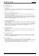
In pursuit of "Saving" Technology ,Epson electronic device. Our Lineup of semiconductors, Liquid crystal displays and quartz devices assists in creating the products of our customers' dreams. Epson IS energy savings. NOTICE • The material is subject to change without notice. • Any part of this material may not be reproduced or duplicated in any form or any means without the written permission of Seiko Epson. • The information, applied circuit, program, using way etc.
RX - 8581 SA / JE / NB Contents 1. Overview...................................................................................................................1 2. Block Diagram ........................................................................................................1 3. Terminal description.............................................................................................2 3.1. Terminal connections ....................................................................................
RX - 8581 SA / JE / NB I2C-Bus Interface Real-time Clock Module RX - 8581 SA / JE / NB • • • • • • • • • • • Features built-in 32.768-kHz crystal oscillator, frequency adjusted 2 Supports I C-Bus's high speed mode (400 kHz) Alarm interrupt function for day, date, hour, and minute settings Fixed-cycle timer interrupt function (Seconds, minutes) Time update interrupt function (FOE and FOUT pins) 32.
RX - 8581 SA / JE / NB 3. Terminal description 3.1. Terminal connections RX - 8581 SA RX - 8581 JE SOP − 14 pin #1 VSOJ − 20 pin # 14 #7 SON − 22 pin #1 # 14 # 10 # 11 #1 # 14 # 11 (#12) #8 No. Pin terminal No. Pin terminal 1 2 3 4 5 6 7 RX - 8581 NB N.C. SCL SDA N.C. GND N.C. / INT 14 13 12 11 10 9 8 FOUT N.C. N.C. VDD FOE N.C. N.C. No. Pin terminal No. Pin terminal 1 2 3 4 5 6 7 8 9 10 N.C. N.C. FOE VDD FOUT SCL SDAT ( VDD ) GND / INT 20 19 18 17 16 15 14 13 12 11 N.C. N.C. N.C. N.
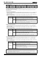
RX - 8581 SA / JE / NB 4. Absolute Maximum Ratings GND = 0 V Item Symbol Condition Supply voltage Input voltage (1) Input voltage (2) Output voltage (1) Output voltage (2) VDD VIN1 VIN2 VOUT1 VOUT2 Storage temperature TSTG Between VDD and GND FOE pin SCL and SDA pins FOUT pin SDA and /INT pins When stored separately, without packaging Rating −0.3 GND−0.3 GND−0.3 GND−0.3 GND−0.3 to to to to to Unit +7.0 VDD+0.3 +8.0 VDD+0.3 +8.0 V V V V V −55 to +125 °C 5.
RX - 8581 SA / JE / NB * Unless otherwise specified, GND = 0 V , VDD = 1.8 V to 5.5 V , Ta = −40 °C to +85 °C 7.2. AC Characteristics Item Symbol SCL clock frequency Start condition setup time Start condition hold time Data setup time Data hold time Stop condition setup time Bus idle time between start condition and stop condition Time when SCL = "L" Time when SCL = "H" Rise time for SCL and SDA Fall time for SCL and SDA Allowable spike time on bus FOUT duty Condition Min. Typ. Max.
RX - 8581 SA / JE / NB 8. Use Methods 8.1. Overview of Functions 1) Clock functions This function is used to set and read out month, day, hour, date, minute, second, and year (last two digits) data. Any (two-digit) year that is a multiple of 4 is treated as a leap year and calculated automatically as such until the year 2099. ∗ For details, see "8.2. Description of Registers".
RX - 8581 SA / JE / NB 8.2. Description of Registers 8.2.1.
RX - 8581 SA / JE / NB 8.2.2. Control register (Reg F) Address Function F bit 7 bit 6 bit 5 bit 4 bit 3 bit 2 bit 1 bit 0 Control Register ! ! UIE TIE AIE ! STOP RESET (Default) (0) (0) (−) (−) (−) (0) (−) (−) ∗1) The default value is the value that is read (or is set internally) after powering up from 0 V. ∗2) "o" indicates write-protected bits. A zero is always read from these bits. ∗3) "−" indicates no default value has been defined.
RX - 8581 SA / JE / NB 4) STOP bit This bit is used to stop functions related to the RTC's internal counter operations. Writing a "1" to this bit stops the counter operations. Writing a "0" to this bit cancels stop status (restarts operations). ∗ For optimum performance, do not use this bit for functions other than the clock and calendar functions. Data Description STOP [Normal operation mode] 0 This bit is used to cancel stop status for (i.e., restart) the clock and calendar function.
RX - 8581 SA / JE / NB 8.2.3. Flag register (Reg-E) Address Function bit 7 E Flag register (Default) bit 6 bit 5 bit 4 bit 3 bit 2 bit 1 ! ! UF TF (0) (0) (−) (−) bit 0 AF ! VLF ! (−) (0) (1) (0) ∗1) The default value is the value that is read (or is set internally) after powering up from 0 V. ∗2) "o" indicates write-protected bits. A zero is always read from these bits. ∗3) "−" indicates a default value is undefined.
RX - 8581 SA / JE / NB 8.2.4. Extension register (Reg-D) Address Function bit 7 bit 6 bit 5 bit 4 D Extension Register TEST WADA USEL TE (Default) (0) (−) (−) (−) ∗1) ∗2) ∗3) bit 3 bit 2 bit 1 bit 0 ! ! TSEL1 TSEL0 (0) (0) (−) (−) The default value is the value that is read (or is set internally) after powering up from 0 V. "o" indicates write-protected bits. A zero is always read from these bits. "−" indicates a default value is undefined.
RX - 8581 SA / JE / NB 8.2.6. Clock counter (Reg - 0 ∼ 2) Address Function bit 7 bit 6 bit 5 bit 4 bit 3 bit 2 bit 1 bit 0 0 1 2 SEC MIN HOUR ! ! 40 40 ! ! 20 20 20 10 10 10 8 8 8 4 4 4 2 2 2 1 1 1 ∗) "o" indicates write-protected bits. A zero is always read from these bits. • The clock counter counts seconds, minutes, and hours. • The data format is BCD format. For example, when the "seconds" register value is "0101 1001" it indicates 59 seconds.
RX - 8581 SA / JE / NB 8.2.8. Calendar counter (Reg 4 to 6) Address Function bit 7 bit 6 bit 5 bit 4 bit 3 bit 2 bit 1 bit 0 4 5 6 DAY MONTH YEAR ! ! 20 ! ! ! 80 40 20 10 10 10 8 8 8 4 4 4 2 2 2 1 1 1 ∗) "o" indicates write-protected bits. A zero is always read from these bits. • The auto calendar function updates all dates, months, and years from January 1, 2001 to December 31, 2099. • The data format is BCD format.
RX - 8581 SA / JE / NB 8.3. Fixed-cycle Timer Interrupt Function The fixed-cycle timer interrupt generation function generates an interrupt event periodically at any fixed cycle set between 244.14 µs and 4095 minutes. When an interrupt event is generated, the /INT pin goes to low level and "1" is set to the TF bit to report that an event has occurred.
RX - 8581 SA / JE / NB 8.3.2. Related registers for function of time update interrupts. Address Function bit 7 bit 6 B C D E F ∗1) ∗2) Timer Counter 0 Timer Counter 1 Extension Register Flag Register Control Register bit 5 bit 4 bit 3 bit 2 bit 1 bit 0 16 • TE TF TIE 8 2048 4 1024 2 512 TSEL1 1 256 TSEL0 128 • 64 • 32 • TEST WADA USEL ! ! UF ! ! UIE ! ! AF ! VLF ! AIE ! STOP RESET "o" indicates write-protected bits. A zero is always read from these bits.
RX - 8581 SA / JE / NB 5) TIE (Timer Interrupt Enable) bit When a fixed-cycle timer interrupt event occurs (when the TF bit value changes from "0" to "1"), this bit's value specifies whether an interrupt signal is generated (/INT status changes from Hi-Z to low) or is not generated (/INT status remains Hi-Z). Data Description TIE 1) When a fixed-cycle timer interrupt event occurs, an interrupt signal is not generated or is canceled (/INT status remains Hi-Z).
RX - 8581 SA / JE / NB 8.4. Time Update Interrupt Function The time update interrupt function generates interrupt events at one-second or one-minute intervals, according to the timing of the internal clock. When an interrupt event occurs, the UF bit value becomes "1" and the /INT pin goes to low level to indicate that an event has occurred.
RX - 8581 SA / JE / NB 8.4.2. Related registers for time update interrupt functions. Address Function bit 7 bit 6 bit 5 bit 4 bit 3 bit 2 bit 1 bit 0 D E F Extension Register Flag Register Control Register TEST WADA TE ! ! TSEL1 TSEL0 ! ! TF AF ! VLF ! ! ! USEL UF UIE TIE AIE ! STOP RESET ∗) "o" indicates write-protected bits. A zero is always read from these bits.
RX - 8581 SA / JE / NB 8.5. Alarm Interrupt Function The alarm interrupt generation function generates interrupt events for alarm settings such as date, day, hour, and minute settings. When an interrupt event occurs, the AF bit value is set to "1" and the /INT pin goes to low level to indicate that an event has occurred. ∗ Example of /INT operation AIE = " 1 " ( AF = " 0 " → " 1 " ) AF = " 1 " → " 0 " or AIE = " 1 " → " 0 " 8.4.1.
RX - 8581 SA / JE / NB 8.5.2.
RX - 8581 SA / JE / NB 3) AF (Alarm Flag) bit When this flag bit value is already set to "0", occurrence of an alarm interrupt event changes it to "1". When this flag bit value is "1", its value is retained until a "0" is written to it. Data Description AF 0 Write The AF bit is cleared to zero to prepare for the next status detection ∗ Clearing this bit to zero enables /INT low output to be canceled (/INT remains Hi-Z) when an alarm interrupt event has occurred.
RX - 8581 SA / JE / NB 8.6. Reading/Writing Data via the I2C Bus Interface 8.6.1. Overview of I2C-BUS 2 The I C bus supports bi-directional communications via two signal lines: the SDA (data) line and SCL (clock) line. A combination of these two signals is used to transmit and receive communication start/stop signals, data transfer signals, acknowledge signals, and so on. Both the SCL and SDA signals are held at high level whenever communications are not being performed.
RX - 8581 SA / JE / NB 2 8.6.3. Starting and stopping I C bus communications START Repeated START(RESTART) condition condition STOP condition SCL [S] [ Sr ] [P] SDA 0.95 s ( Max. ) 1) START condition, repeated START condition, and STOP condition (1) START condition • The SDA level changes from high to low while SCL is at high level. (2) STOP condition • This condition regulates how communications on the I2C-BUS are terminated. The SDA level changes from low to high while SCL is at high level.
RX - 8581 SA / JE / NB 8.6.4. Data transfers and acknowledge responses during I2C-BUS communications 1) Data transfers Data transfers are performed in 8-bit (1 byte) units once the START condition has occurred. There is no limit on the amount (bytes) of data that are transferred between the START condition and STOP condition. (However, the transfer time must be no longer than 0.95 seconds.) The address auto increment function operates during both write and read operations.
RX - 8581 SA / JE / NB 2 8.6.6. I C bus protocol In the following sequence descriptions, it is assumed that the CPU is the master and the RX-8581 is the slave. a. Address specification write sequence Since the RX-8581 includes an address auto increment function, once the initial address has been specified, the RX-8581 increments (by one byte) the receive address each time data is transferred. (1) CPU transfers start condition [S].
RX - 8581 SA / JE / NB 8.7. Backup and Recovery VDD VCLK 0V t R1 tF t R2 Back up Item Symbol Min. Power supply drop time tF 2 µs /V Initial power-up time t R1 1 µs /V Clock maintenance power-up time t R2 1 µs /V Typ. Max. 10 ms /V 8.8.
RX - 8581 SA / JE / NB 9. External Dimensions / Marking Layout RX-8581 SA (SOP - 14 pin) • External dimensions • Recommended soldering 10.1 ± 0.2 #14 0° - 10° #8 1.4 5.0 7.4 ± 0.2 R8581 E 1234A 5.4 0.6 #1 #7 0.05 Min. 0.35 1.27 1.4 0.15 1.27 3.2 ± 0.1 0.7 1.27 × 6 = 7.62 1.2 Unit : mm ∗ The crystal oscillator's metal case may be visible in the area (on top) indicated in broken lines but this has no effect on the device's characteristics.
RX - 8581 SA / JE / NB 10. Reference Data (1) Example of frequency and temperature characteristics × 10-6 θT = +25 °C Typ. α = -0.035 × 10⁻⁶ Typ. 1. Frequency and temperature characteristics can be approximated using the following equations. 2 ∆fT = α (θT - θX) : Frequency deviation in any ∆fT temperature 2 α (1 / °C ) : Coefficient of secondary temperature -6 2 (−0.035±0.
RX - 8581 SA / JE / NB 11. Application notes 11.1. Notes on handling This module uses a C-MOS IC to realize low power consumption. handling. Carefully note the following cautions when (1) Static electricity While this module has built-in circuitry designed to protect it against electrostatic discharge, the chip could still be damaged by a large discharge of static electricity. Containers used for packing and transport should be constructed of conductive materials.
Application Manual Distributor AMERICA EPSON ELECTRONICS AMERICA, INC. HEADQUARTER Atlanta Office Boston Office Chicago Office El Segundo Office 150 River Oaks Parkway, San Jose, CA 95134, U.S.A. Phone: (1)800-228-3964 (Toll free) : (1)408-922-0200 (Main) Fax: (1)408-922-0238 http://www.eea.epson.com 3010 Royal Blvd. South, Ste. 170, Alpharetta, GA 30005, U.S.A. Phone: (1)877-332-0020 (Toll free) : (1)770-777-2078 (Main) Fax: (1)770-777-2637 301Edgewater Place, Ste. 120, Wakefield, MA 01880, U.S.A.