
Clock User Manual

RX
-
8581
SA
/
JE
/
NB
Page - 15 MQ372-02
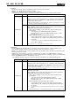
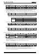
5) TIE (Timer Interrupt Enable) bit
When a fixed-cycle timer interrupt event occurs (when the TF bit value changes from "0" to "1"), this bit's value
specifies whether an interrupt signal is generated (/INT status changes from Hi-Z to low) or is not generated
(/INT status remains Hi-Z).
TIE
Data Description
0
1) When a fixed-cycle timer interrupt event occurs, an interrupt signal is not
generated or is canceled (/INT status remains Hi-Z).
2) When a fixed-cycle timer interrupt event occurs, the interrupt signal is
canceled (/INT status changes from low to Hi-Z).
∗
Even when the TIE bit value is "0" another interrupt event may change the /INT status to low (or
may hold /INT = "L").
Write/Read
1
When a fixed-cycle timer interrupt event occurs, an interrupt signal is
generated (/INT status changes from Hi-Z to low).
∗
When a fixed-cycle timer interrupt event has been generated low-level output from the /INT pin
occurs only when the value of the control register's TIE bit is "1". Up to 7.8 ms after the interrupt
occurs, the /INT status is automatically cleared (/INT status changes from low to Hi-Z).
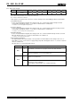
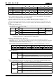
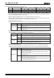
8.3.3. Fixed-cycle timer interrupt interval (example)
Source clock
Timer
Counter
setting
4096 Hz
TSEL1,0 = 0,0
64 Hz
TSEL1,0 = 0,1
"Second"
update
TSEL1,0 = 1,0
"Minute"
update
TSEL1,0 = 1,1
0
− − − −
1
244.14 µs
15.625 ms 1 s 1 min
2
488.28 µs
31.25 ms 2 s 2 min
•
•
•
•
•
•
•
•
•
•
•
•
•
•
•
41 10.010 ms 640.63 ms 41 s 41 min
205 50.049 ms 3.203 s 205 s 205 min
410 100.10 ms 6.406 s 410 s 410 min
2048 500.00 ms 32.000 s 2048 s 2048 min
•
•
•
•
•
•
•
•
•
•
•
•
•
•
•
4095 0.9998 s 63.984 s 4095 s 4095 min
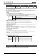
• Time error in fixed-cycle timer
A time error in the fixed-cycle timer will produce a positive or negative time period error in the selected
source clock. The fixed-cycle timer's time is within the following range relative to the time setting.
(Fixed-cycle timer's time setting (∗) − source clock period) to (timer's time setting)
∗) The timer's time setting = source clock period × timer counter's division value.
∗ The time actually set to the timer is adjusted by adding the time described above to the
communication time for the serial data transfer clock used for the setting.
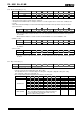
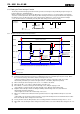
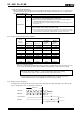
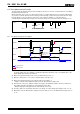
8.3.4. Fixed-cycle timer start timing
Counting down of the fixed-cycle timer value starts at the rising edge of the SCL signal that occurs when the TE
value is changed from "0" to "1" (after bit 0 is transferred).
TSEL0
TE
0
0
TSEL1
Operation of timer
/INT pin
SDA pin
SCL pin
Internal timer
A
ddress D
A
CK