MF599-06 CMOS 4-BIT SINGLE CHIP MICROCOMPUTER S1C62 Family Development Tool Reference Manual
NOTICE No part of this material may be reproduced or duplicated in any form or by any means without the written permission of Seiko Epson. Seiko Epson reserves the right to make changes to this material without notice.
S1C62 Family Development Tool Reference Manual Preface The explanation covering the outline and operation of the development support tools for the CMOS 4-bit Single Chip Microcomputer S1C62 Family has been divided into the following parts. I. II. III. IV. V. VI. VII. VIII. IX.
The information of the product number change Starting April 1, 2001, the product number will be changed as listed below. To order from April 1, 2001 please use the new product number. For further information, please contact Epson sales representative.
I S1C62 FAMILY DEVELOPMENT TOOL INTRODUCTION This part explains the composition of the development support tool for the 4-bit Single Chip Microcomputer S1C62 Family and the developmental environment.
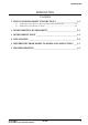
INTRODUCTION INTRODUCTION Contents 1 TYPES OF DEVELOPMENT SUPPORT TOOLS ____________________ I-1 1.1 1.2 Composition of the Software Development Tools S5U1C62xxxD ........................... I-1 Composition of the Hardware Tools .......................................................................
INTRODUCTION 1 TYPES OF DEVELOPMENT SUPPORT TOOLS Here we will explain the composition of the software and hardware for the development support tools. 1.1 Composition of the Software Development Tools S5U1C62xxxD The below software are included in the software development support tools used in each S1C62XXX model. 1. 2. 3. 4. 5. 6. 7. Development Tool Management System DMS6200 .. Menu selections for each software / start-up software Cross Assembler ASM62XX ......................................
INTRODUCTION 2 DEVELOPMENTAL ENVIRONMENT The software product of the development support tool S5U1C62xxxD operates on the following host systems: • IBM PC/AT (at least PC-DOS Ver. 2.0) When developing the S1C62XXX, the above-mentioned host computer, editor, P-ROM writer, printer, etc. must be prepared by the user in addition to the development tool which is normally supported by Seiko Epson.
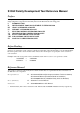
INTRODUCTION *1, *2 *1 Determination of software specifications Determination of hardware specifications *2, *3, *4 *4, *5 Flow chart generation and coding *4, *5 Development support tool selection on menu of Development Tool Management System DMS6200 Coding sheet Coding sheet Source file generation by using editor Source file generation by using editor C2XXYYY .DAT *4, *5 Melody generation and coding Program source file Function option list C2XXYYY .
INTRODUCTION 4 INSTALLATION The S5U1C62xxxD tools are included on the CD-ROM of the S5U1C62000A (S1C60/62 Family Assembler Package), and they can be installed in your hard disk using the installer (Setup.exe) on the CD-ROM. Refer to the "S5U1C62000A Manual" for how to install the S5U1C62xxxD tools. Note I-4 The DMS6200 configures a menu from files that are located in the current directory. Therefore, do not move the development tools from the directory in which the DMS6200 exists.
INTRODUCTION 5 DIFFERENCES FROM MODEL TO MODEL AND PRECAUTIONS There may be some models in which the following two types software tools contained in the S5U1C62xxxD are not included. (1) Segment Option Generator SOG62XX This is not included in the software tools of models in which the segment option has not been set. (2) Melody Assembler MLA628X This is not included in the software tools for the models (Other than S1C62N8X) that do not have the melody function.
INTRODUCTION 6 TROUBLESHOOTING Tool ICE S5U1C62000H Problem Nothing appears on the screen, or nothing works, after activation. The ICE fuse cut immediately after activation. appears on the screen immediately after activation. appears on the screen immediately after activation. Immediate values A (10) and B (11) cannot be entered correctly with the A command. is displayed by the SD command.
INTRODUCTION Tool ASM62XX Problem An R error occurs although the final page is passed. MDC62XX Activation is impossible. MLA628X No melody is output. Evaluation The evaluation board does not work when it is used independently. board S5U1C62xxxE Target segment does not light. S1C62 FAMILY DEVELOPMENT TOOL REFERENCE MANUAL Remedy measures The cross assembler is designed to output "R error" every time the page is changed.
II DEVELOPMENT TOOL MANAGEMENT SYSTEM DMS6200 This part mainly explains how to operate the Development Tool Management System DMS6200.
DEVELOPMENT TOOL MANAGEMENT SYSTEM DMS6200 DEVELOPMENT TOOL MANAGEMENT SYSTEM Contents 1 DIFFERENCES DEPENDING ON THE MODEL __________________ II-1 2 DMS6200 OUTLINE ___________________________________________ II-1 3 DMS6200 OPERATION PROCEDURE ___________________________ II-2 S1C62 FAMILY DEVELOPMENT TOOL REFERENCE MANUAL EPSON II-i
DEVELOPMENT TOOL MANAGEMENT SYSTEM DMS6200 1 DIFFERENCES DEPENDING ON THE MODEL The DMS6200 is a software tool that is common to the all models of the S1C62 Family and there is no difference in operating procedure. However, the content of such things as the menu screen may vary due to differences in the configuration of the software for each model and differences in the directory content in the DMS6200.
DEVELOPMENT TOOL MANAGEMENT SYSTEM DMS6200 3 DMS6200 OPERATION PROCEDURE Set the directory containing the respective software development support tools into the current directory prior to activating the DMS6200. Since the development support tools each require input files (e.g., source file), first create the input files according to the support tool manuals and then perform the following operations: (1) The following is entered on the current drive: indicates the return key.
DEVELOPMENT TOOL MANAGEMENT SYSTEM DMS6200 (3) Input the number of the development support tool you wish to start and then press the "RETURN" key. Next, the screen for entering the source file will be displayed. Input Number ? [1 ] (4) The following sample screen is the screen which will be displayed when ASM62XX is selected. Input the number of the source file. Pressing the "ESC" key here will return the previous screen.
III CROSS ASSEMBLER ASM62XX This part mainly explains how to operate the Cross Assembler ASM62XX for the S1C62 Family, and how to generate source files.
CROSS ASSEMBLER ASM62XX CROSS ASSEMBLER ASM62XX Contents 1 DIFFERENCES DEPENDING ON THE MODEL __________________ III-1 2 ASM62XX OUTLINE __________________________________________ III-2 2.1 2.2 Outline ................................................................................................................... III-2 ASM62XX Input/Output Files ................................................................................ III-2 3 ASM62XX OPERATION PROCEDURE __________________________ III-3 3.1 3.
CROSS ASSEMBLER ASM62XX 1 DIFFERENCES DEPENDING ON THE MODEL Since the memory capacity will vary with each model of the S1C62 Family you must pay attention to the following points when preparing a program. The limiting items for each model are indicated in the "S5U1C62xxxD Manual". ■ ROM area The ROM capacity will vary depending on the model.
CROSS ASSEMBLER ASM62XX 2 ASM62XX OUTLINE 2.1 Outline The ASM62XX cross assembler (the ASM62XX in this manual) is an assembler program for generating the machine code used by the S1C62XXX 4-bit, single-chip microcomputers. It can be used under PC-DOS. The Cross Assembler ASM62XX will assemble the program source files which have been input by the user's editor and will generate an object file in IntelHex format and assembly list file.
CROSS ASSEMBLER ASM62XX 3 ASM62XX OPERATION PROCEDURE This section explains how to operate ASM62XX. 3.1 Starting ASM62XX When starting ASM62XX, enter the following at DOS command level (when a prompt such as A> is being displayed): ASM62XX _ [drive-name:] source-file-name [.shp] _ [-N] _ indicates a blank. A parameter enclosed by [ ] can be omitted. indicates the return key. When starting ASM62XX through the DMS6200, selects the "ASM62XX.
CROSS ASSEMBLER ASM62XX Example 1: Basic assembly example A>ASM62XX C2XXYYY The source file "C2XXYYY.DAT" is input from drive A, and the object files "C2XXYYYH.HEX" and "C2XXYYYL.HEX" and the assembly listing file "C2XXYYY.PRN" are output to drive A. A>ASM62XX B:C2XXYYY The source file "C2XXYYY.DAT" is input from drive B, and the object files "C2XXYYYH.HEX" and "C2XXYYYL.HEX" and the assembly listing file "C2XXYYY.PRN" are output to drive B. A>ASM62XX C2XXYYY.BBZ The source file "C2XXYYY.
CROSS ASSEMBLER ASM62XX 3.2 Selecting Auto-Page-Set Function After the start-up message, the following message is displayed, prompting the user to select the auto-pageset function. DO YOU NEED AUTO PAGE SET?(Y/N) Press the "Y" key if selecting the auto-page-set function, or the "N" key if not selecting it. At this stage, the user can also return to the DOS command level by entering "CTRL" + "C" key.
CROSS ASSEMBLER ASM62XX 4 SOURCE FILE FORMAT The source file contains the source program consisting of S1C62XXX instructions (mnemonics) and pseudo-instructions, and is produced using an editor such as EDLIN. Refer to the "S1C6200/6200A Core CPU Manual" and the "S1C6xxx Technical Manual (Software)" for instruction sets. 4.1 Source File Name A desired file name not exceeding seven characters in length can be assigned to each source file. The format must be as follows: C2XXYYY.DAT "YYY" of the "C2XXYYY.
CROSS ASSEMBLER ASM62XX 4.2.2 Mnemonic field The mnemonic field is used for an instruction mnemonic or a pseudo-instruction. 4.2.3 Operand field The operand field is used for the operands of the instruction. The form of each operand and the number of operands depend on the kind of instruction.
CROSS ASSEMBLER ASM62XX 4.3.2 Symbol A symbol is an index that indicates a numeric or character constant, and must be defined before its value is referenced (usually at the beginning of the program). The defined symbol can be used as the operand that specifies immediate data in an instruction. Example: ON OFF EQU EQU : LD : LD : 1 0 (See Section 4.5 for EQU.) A,ON ; = LD A,1 A,OFF ; = LD A,0 4.4 Constant and Operational Expression This section explains the immediate data description formats. 4.
CROSS ASSEMBLER ASM62XX 4.4.3 Operator When specifying a value for an item such as an operand, an operational expression can be written instead of a constant, and its result can be used as the value. Labels and symbols as well as constants can be used as terms in expressions. These values are processed as 13-bit data (bit 14 and subsequent high-order bits are ignored); the operation result also consists of 13 bits.
CROSS ASSEMBLER ASM62XX ■ Relational operators A logical operator compares two terms; if the relationship between the terms is as the operator specifies, 1FFFH (true) is returned; if not, 0 (false) is returned.
CROSS ASSEMBLER ASM62XX 4.5 Pseudo-Instructions There are four types of pseudo-instruction: data definition, memory setting, assembler control, and macro. These pseudo-instructions as well as operational expressions can be used to govern assembly, and are not executed in the developed program. In the subsequent explanations, the items enclosed by < > in the pseudo-instruction format must be written in the statement (do not write the < > characters themselves).
CROSS ASSEMBLER ASM62XX ■ DW (Define Word)
CROSS ASSEMBLER ASM62XX ■ BANK BANK_ To set the bank (BNK) The BANK pseudo-instruction sets the value of in the bank (BNK) field, and sets the page counter (PCP) and step counter (PCS) to 00H. The BANK pseudo-instruction can be written at multiple locations in the program. However, it cannot be used to specify the current bank (excluding the specification in page 00, step 00) or a previous bank.
CROSS ASSEMBLER ASM62XX ■ SECTION SECTION To change the section The SECTION pseudo-instruction sets the first address of the subsequent section in the location counter. Sections are 16-step areas starting from the beginning of the program memory.
CROSS ASSEMBLER ASM62XX 4.5.3 Assembler control pseudo-instructions ■ END END To terminate assembly The END statement terminates assembly. All statements following the END statement are ignored. Be sure to write this statement at the end of the program. If it is missing, assembly may not terminate. A label can be written before the END statement, but it cannot be referenced because it is not cataloged in the label table. 4.
CROSS ASSEMBLER ASM62XX 4.6.2 Macro-definitions The macro-definition should be done by using the MACRO and the ENDM instructions (pseudo-instruction). ■ MACRO ~ ENDM _ MACRO_ [, ...] Statement : ENDM The statement block enclosed by a MACRO pseudo-instruction and an ENDM pseudo-instruction is defined as a macro. Any name can be assigned to the macro as long as it conforms to the rules regarding the characters, length, and label field.
CROSS ASSEMBLER ASM62XX 4.6.3 Macro-calls The defined macro-name can be called from any location in the program by using the following format: [
CROSS ASSEMBLER ASM62XX Assembly listing file LISTING OF ASM62XX LINE BANK PCP PCS 1 2 3 4 5 6 7 8 9 10 11 12 13 14 15 16 17 18 19 20 21 22 23 24 0 2 00 25 0 2 01 26 0 2 02 27 0 2 03 28 0 2 04 29 0 2 05 30 0 2 06 31 0 2 07 32 33 34 0 2 08 35 0 2 09 36 0 2 0A 37 0 2 0B 38 0 2 0C 39 0 2 0D 40 0 2 0E 41 0 2 0F 42 43 III-18 C2XX0A1.PRN OBJ 0000= 0002= 0005= 0000= 0010= 0008= 0001= 0004= ........
CROSS ASSEMBLER ASM62XX 5 ERROR MESSAGES If an error occurs during assembly, ASM62XX outputs the appropriate error symbol or error message listed below to the console and assembly listing file. Only a single error symbol is output at the beginning (column 1) of the statement that caused the error. (If two or more errors occurred, only the error with highest priority is output.) The following error symbols are listed in order of priority, starting with the one with the highest priority. S (Syntax Error) ..
CROSS ASSEMBLER ASM62XX APPENDIX ASM62XX EXECUTION EXAMPLE 1) Source file (C2XX0A0.DAT) A>TYPE C2XX0A0.
CROSS ASSEMBLER ASM62XX 2) Running the assembler (display on the console) A>ASM62XX C2XX0A0 *** E0C62XX CROSS ASSEMBLER. --- VERSION 2.
CROSS ASSEMBLER ASM62XX 3) Assembly listing file (C2XX0A0.PRN) A>TYPE C2XX0A0.PRN LISTING OF ASM62XX LINE BANK PCP PCS 1 2 3 4 5 6 7 0 0 00 8 0 0 01 9 0 0 02 10 0 0 03 11 12 13 14 0 0 E0 15 0 0 E1 16 0 0 E2 17 0 0 E3 18 0 0 E4 19 0 0 E5 20 0 0 E6 21 22 M 23 P 24 P 25 0 0 E7 S 26 0 0 E8 O 27 0 0 E9 U 28 0 0 EA 29 ! 30 31 32 33 0 0 FF R 34 0 1 00 35 C2XX0A0.PRN ........
CROSS ASSEMBLER ASM62XX 4) Object files (C2XX0A0H.HEX, C2XX0A0L.HEX) A>TYPE C2XX0A0L.
IV MELODY ASSEMBLER MLA628X This part mainly explains how to operate the Melody Assembler MLA628X for the S1C62 Family, and how to generate source files.
MELODY ASSEMBLER MLA628X MELODY ASSEMBLER MLA628X Contents 1 DIFFERENCES DEPENDING ON THE MODEL __________________ IV-1 2 MLA628X OUTLINE ___________________________________________ IV-1 2.1 2.2 Outline and Execution Flow .................................................................................. IV-1 MLA628X Input/Output Files ................................................................................
MELODY ASSEMBLER MLA628X 1 DIFFERENCES DEPENDING ON THE MODEL The MLA628X is not included in the software tools for models (other than the S1C62N8X) that do not have the melody function. The melody ROM capacity varies depending on the model in models (S1C62N8X) having the melody function. You should be aware that the number of melody data and their bit structure will vary, as a result. The limiting items for each model are indicated in the "S5U1C62N8xD Manual". 2 MLA628X OUTLINE 2.
MELODY ASSEMBLER MLA628X 3 STARTING MLA628X To starting MLA628X, enter the following at the DOS command level (when a prompt such as A> is being displayed): _ indicates a blank. A parameter enclosed by [ ] MLA628X_[drive name:]source filename[.shp]_[-H] can be omitted. indicates the return key. When starting MLA628X through the DMS6200, selects the "MLA628X.EXE" and source file in the menu screen, and input options necessary. ■ Drive name When the source file is in a different drive from MLA628X.
MELODY ASSEMBLER MLA628X Examples: A>MLA628X C28XYYY In this example, the source file "C28XYYY.MDT" is input from drive A, and the melody HEX file "C28XYYYA.HEX", melody assembly list file "C28XYYY.MPR", and melody document file "C28XYYYA.DOC" are created on drive A. A>MLA628X B:C28XYYY In this example, the source file "C28XYYY.MDT" is input from drive B, and the melody HEX file "C28XYYYA.HEX", melody assembly list file "C28XYYY.MPR", and melody document file "C28XYYYA.DOC" are created on drive B.
MELODY ASSEMBLER MLA628X 4 FORMAT OF SOURCE FILE Contents of the source file, created with an editor such as EDLIN, are configured from the S1C628XX melody codes and the pseudo-instructions described later. 4.1 Source File Name The source file can be named with a maximum of any seven characters. As a rule, keep to the following format. C28XYYY.MDT Three alphanumerics are entered in the "YYY" part. Refer to the model name from Seiko Epson. The extension must be ".MDT". 4.
MELODY ASSEMBLER MLA628X (3) Scale field The scale field can be filled in with any scale (C3 through C6#). When inputting the scale data directly, prefix the data with "$". In this case, the input data range is 00H through FDH. Moreover, the rest may be selected by describes "RR" in the scale field. The number of specifiable scales varies depending on the model. (Refer to the "S5U1C62N8xD Manual".) (4) End bit field The instruction indicating the end of the melody is written in the end bit field.
MELODY ASSEMBLER MLA628X 5 PSEUDO-INSTRUCTIONS The pseudo-instruction is for the assembler, and cannot be executed by the melody data after development. In the explanations below, the symbols "<" and ">" used in the pseudo-instruction format indicate the contents of the statement. These symbols are not actually written. "_" indicates one or more spaces or tabs. The symbol, constant, arithmetic expression and so forth is written in "". 5.
MELODY ASSEMBLER MLA628X ■ .TEMPC1 .TEMPC1 = n Sets TEMPC1 (n = 0–15) The TEMPC1 option is set by specifying n as an integer in the range 0 to 15. This setting cannot be omitted. ■ .OCTAVE .OCTAVE = m Sets scale range (m = 32 or 64) Decides the scale range by selecting the specification of the melody multiplier circuit. The specification becomes 32 kHz for m = 32, and the range becomes (C3–C6#).
MELODY ASSEMBLER MLA628X APPENDIX SAMPLE FILES The following input/output files are an example for the MLA6282 case and the data size, etc. will vary depending on the model. ■ Example of Source File .TEMPC0=5 .TEMPC1=8 .
MELODY ASSEMBLER MLA628X SCALE ROM TABLE PAGE S-1 ADRS SCALE CODE C3 D4 F4 F5 G5# A4 B4 A4# $C3 $45 $E3 $97 C6 A5# $42 ----------------RR 04 92 A4 D4 DC B8 C0 BC C3 45 E3 97 E4 E0 42 FF FF FF FF FF FF FF FF FF FF FF FF FF FF FF FF C4 00000 00001 00010 00011 00100 00101 00110 00111 01000 01001 01010 01011 01100 01101 01110 01111 10000 10001 10010 10011 10100 10101 10110 10111 11000 11001 11010 11011 11100 11101 11110 11111 Example of scale ROM table - Hyphens "--" indicate unused code.
MELODY ASSEMBLER MLA628X ■ Example of Assembly List When Error Occurs When an error occurs the code is made FFF forcibly. A value is not entered for the scale ROM. LISTING OF MLA6282 ADRS CODE 0 1 2 3 4 5 6 7 000 062 064 FFF 048 FFF FFF 0A9 10 11 12 13 14 15 16 17 18 19 O 1A 1B 02A 06C 0CE 1B0 092 0D4 056 078 09A 07C FFF 15F S S S C282YYY.MPR 1991-6-01 17:30...PAGE SOURCE .TEMPC0 = 5 .TEMPC1 = 8 .
MELODY ASSEMBLER MLA628X ■ Example of Melody Document File Format :100000000101010101020200FFFFFFFFFFFFFFFFEF :1000100001010002000003FFFFFFFFFFFFFFFFFFE2 :10002000FFFFFFFFFFFFFFFFFFFFFFFFFFFFFFFFE0 :10003000FFFFFFFFFFFFFFFFFFFFFFFFFFFFFFFFD0 :10004000FFFFFFFFFFFFFFFFFFFFFFFFFFFFFFFFC0 :10005000FFFFFFFFFFFFFFFFFFFFFFFFFFFFFFFFB0 :10006000FFFFFFFFFFFFFFFFFFFFFFFFFFFFFFFFA0 :10007000FFFFFFFFFFFFFFFFFFFFFFFFFFFFFFFF90 :00000001FF :10000000C0020486484ACC8FFFFFFFFFFFFFFFFFBF :1000100090525496D85A5DFFFFFFFFFFFFFF
V FUNCTION OPTION GENERATOR FOG62XX This part mainly explains how to operate the Function Option Generator FOG62XX for setting the hardware options of the S1C62 Family.
FUNCTION OPTION GENERATOR FOG62XX FUNCTION OPTION GENERATOR FOG62XX Contents 1 DIFFERENCES DEPENDING ON THE MODEL __________________ V-1 2 FOG62XX OUTLINE __________________________________________ V-1 2.1 2.2 Outline of Function Option Generator ................................................................... V-1 FOG62XX Input/Output Files ................................................................................ V-1 3 OPTION LIST GENERATION ___________________________________ V-2 3.1 3.
FUNCTION OPTION GENERATOR FOG62XX 1 DIFFERENCES DEPENDING ON THE MODEL The set option content will vary depending on the model. Here only the operation will be explained, so you should refer to the "S5U1C62xxxD Manual" concerning the option specifications and the selection screen. 2 FOG62XX OUTLINE 2.1 Outline of Function Option Generator With the 4-bit single-chip S1C62XXX microcomputers, the customer may select hardware options.
FUNCTION OPTION GENERATOR FOG62XX 3 OPTION LIST GENERATION 3.1 Option List Recording Procedure Multiple specifications are available in each option item as indicated in the Option List Example in Section 3.2. Using the "S5U1C62xxxD Manual" as reference, select the specifications that meet the target system and check the appropriate box. Be sure to record the specifications for unused ports too, according to the instructions provided.
FUNCTION OPTION GENERATOR FOG62XX 4 FOG62XX OPERATION PROCEDURE 4.1 Starting FOG62XX To start FOG62XX, enter the following at DOS command level (state in which a prompt such as A> is displayed): indicates the return key. A>FOG62XX When starting FOG62XX through the DMS6200, selects the "FOG62XX.EXE" in the menu screen. When FOG62XX is started, the following message is displayed. *** E0C62XX FUNCTION OPTION GENERATOR. --- Ver 3.
FUNCTION OPTION GENERATOR FOG62XX When the date is set, the following operation selection menu is displayed on the screen. *** OPERATION SELECT MENU *** 1. INPUT NEW FILE 2. EDIT FILE 3. RETURN TO DOS PLEASE SELECT NO.? Enter a number from 1 to 3 to select a subsequent operation. The items indicate the following. 1. INPUT NEW FILE: Used to set new function options. 2. EDIT FILE: Used to read the already-generated function option document file and set or modify the option contents.
FUNCTION OPTION GENERATOR FOG62XX (4) PLEASE INPUT ANY COMMENT Enter any comment. Up to 50 characters may be entered in one line. If 51 or more characters are entered in one line, they are ignored. Up to 10 comment lines may be entered. To end entry of comments, press the RETURN key " ".
FUNCTION OPTION GENERATOR FOG62XX (5) PLEASE INPUT ANY COMMENT When modifying a comment, enter all the comment lines anew, beginning with the first line; comment data cannot be partially modified. Previously entered comment data can be used by pressing the RETURN key " ". The input condition are the same as for new settings. (6) PLEASE INPUT EDIT NO.? Enter the number of the function option to be modified, then start setting the option contents.
FUNCTION OPTION GENERATOR FOG62XX 4.5 HEX File Generation and EPROM Selection When setting function options setting is completed, the following message is output to ask the operator whether to generate the HEX file. END OF OPTION SETTING. DO YOU MAKE HEX FILE (Y/N) ? Y When debugging the program with evaluation board, HEX file C2XXYYYF.HEX is needed. . . (1) *** OPTION EPROM SELECT MENU *** 1. 2. 3. 4. Note 27C64 27C128 27C256 27C512 . . (2) PLEASE SELECT NO.? 2 2.
VI SEGMENT OPTION GENERATOR SOG62XX This part mainly explains how to operate the Segment Option Generator SOG62XX for setting the segment options of the S1C62 Family.
SEGMENT OPTION GENERATOR SOG62XX SEGMENT OPTION GENERATOR SOG62XX Contents 1 DIFFERENCES DEPENDING ON THE MODEL __________________ VI-1 2 SOG62XX OUTLINE ___________________________________________ VI-1 2.1 2.2 Outline and Execution Flow .................................................................................. VI-1 SOG62XX Input/Output Files ................................................................................ VI-2 3 OPTION LIST GENERATION ___________________________________ VI-3 3.
SEGMENT OPTION GENERATOR SOG62XX 1 DIFFERENCES DEPENDING ON THE MODEL The segment output specific, display memory capacity and address will vary depending on the model. Here the explanation will focus on the method of operation. For the optional specifications, we will provide an outline explanation as an example for the case of models with standard segment specifications that are set by the four terminal common output, so you should refer to the "S5U1C62xxxD Manual" for details on each model.
SEGMENT OPTION GENERATOR SOG62XX 2.2 SOG62XX Input/Output Files SOG62XX reads a source file containing segment port specification, and output following files. ■ Segment option source file (C2XXYYY.SEG) The specifications of segment ports must be set in the segment source file (input file for SOG62XX). If the segment source file is not generated, SOG62XX stops execution. Generate the segment source file using an editor such as EDLIN while referencing the option list.
SEGMENT OPTION GENERATOR SOG62XX 3 OPTION LIST GENERATION 3.1 Example of Option List The following table shows an example of the option list in case of the four commons. Refer to the "S5U1C62xxxD Manual" for the option list of each model.
SEGMENT OPTION GENERATOR SOG62XX 4 SOG62XX OPERATION PROCEDURE 4.1 Creating Segment Option Source File The SOG62XX needs, as an input file, a segment option source file containing the specifications for the segment output ports. Using the editor, generate this source file by referencing the contents of the option list. Use the following file name. For "YYY", enter the string distributed by Seiko Epson. C2XXYYY.
SEGMENT OPTION GENERATOR SOG62XX • Each SEG port number corresponds to an actual device, so it must be unique. Moreorve, data descriptions in accordance with the following format are required for segments SEG0–SEG25. • Off areas COM0 to COM3, write three successive "---" (3 hyphens) as data for unused areas. SEG port numbers are needed even if the ports themselves will not be used, so write "---" (3 hyphens) for all areas COM0 to COM3.
SEGMENT OPTION GENERATOR SOG62XX 4.2 Starting SOG62XX To start SOG62XX, enter the following at the DOS command level (state in which a prompt such as A> is displayed): _ indicates a blank. A parameter enclosed by [ ] can be omitted. A>SOG62XX_[-H] indicates the return key. When starting SOG62XX through the DMS6200, selects the "SOG62XX.EXE" in the menu screen, and input options necessary. The current drive must contain the segment option source file (C2XXYYY.SEG).
SEGMENT OPTION GENERATOR SOG62XX 4.3 Input File Selection *** SOURCE FILE(S) *** C2XX0A0 PLEASE INPUT PLEASE INPUT PLEASE INPUT (ONE LINE IS C2XX0B0 C2XX0B1 C2XX0C0 SEGMENT SOURSE FILE NAME? C2XX0A0 USER'S NAME? SEIKO EPSON CORP. ANY COMMENT 50 CHR)? TOKYO DESIGN CENTER ? 421-8 HINO HINO-SHI TOKYO 191 JAPAN ? . . (1) . . (2) . . (3) . . (4) (1) *** SOURCE FILE(S) *** • H option use Will display the segment option source files on the current drive.
SEGMENT OPTION GENERATOR SOG62XX 4.4 HEX File Generation and EPROM Selection When input file selection is completed, the following message is output to ask the operator whether to generate the HEX file. END OF OPTION SETTING. DO YOU MAKE HEX FILE (Y/N) ? Y . . (1) *** OPTION EPROM SELECT MENU *** 1. 2. 3. 4. 27C64 27C128 27C256 27C512 . . (2) PLEASE SELECT NO.? 2 2. 27C128 SELECTED (1) DO YOU MAKE HEX FILE (Y/N)? When debugging the program with evaluation board, HEX file C2XXYYYS.
SEGMENT OPTION GENERATOR SOG62XX 5 ERROR MESSAGES If an error is detected in the segment option source file, an error message is displayed. In this case, the segment option HEX file is not generated, and the segment option document file consisting of the segment option source file and an error message is generated. Note In the following examples, there are cases of models where the common output is 4 terminals, the segment output is 26 terminals and the 900H–AFFH is set in the display memory area.
SEGMENT OPTION GENERATOR SOG62XX D: Duplication error This type of error occurs when the same data (SEG port No., segment memory address, or data bit) is specified more than once. Correct the segment option source file so that each data item is unique in the description. Example: D 20 19 A30 A31 A32 A31 S D 23 22 A60 A61 A31 A31 S "A31" is used more then once Duplication is SEG NO. 19 COM NO. 3 Duplication is SEG NO. 22 COM NO. 3 Message "Duplication is ...
VII EVALUATION BOARD S5U1C62xxxE This part explains the function of the Evaluation Board S5U1C62xxxE, a debugging tool for the S1C62XXX, and the operation of the evaluation board.
EVALUATION BOARD S5U1C62XXXE EVALUATION BOARD S5U1C62xxxE Contents 1 DIFFERENCES DEPENDING ON THE MODEL __________________ VII-1 2 S5U1C62XXXE OUTLINE ______________________________________ VII-1 3 PRECAUTIONS _______________________________________________ VII-2 3.1 3.2 Precautions for Operation ..................................................................................... VII-2 Differences from Actual IC ....................................................................................
EVALUATION BOARD S5U1C62XXXE 1 DIFFERENCES DEPENDING ON THE MODEL The S5U1C62xxxE has the same functions as the actual IC (S1C62XXX). Although the method of operation and other functions are the same, the terminal layout of the I/O and LCD connectors and the input/output signal specifications are different. The layout in the top panel is also different. Refer to the "S5U1C62xxxE Manual" included with the hardware for details on each model.
EVALUATION BOARD S5U1C62XXXE 3 PRECAUTIONS Take the following precautions when using the S5U1C62xxxE: 3.1 Precautions for Operation • Turn the power of all equipment off before connecting or disconnecting cables. • To turn the POWER switch of the S5U1C62xxxE off, then on again, wait for at least 10 seconds after turning off before turning on. • When ROMs are inserted into the L and H ROM sockets, lock the lever securely by positioning it horizontally.
EVALUATION BOARD S5U1C62XXXE 4 NAMES AND FUNCTIONS OF PARTS This section describes the names and functions of the parts of the S5U1C62xxxE. 4.1 Basic Functions The S5U1C62xxxE has the following basic functions: ■ Program execution (Run function) Install the EPROM containing the application program and execute the program. ■ Single-step program operation (Single-step function) Programs may be run instruction by instruction to check the internal state of the CPU as it changes with each instruction.
EVALUATION BOARD S5U1C62XXXE • BREAK POINT switches (BB, BP, BS) These switches set a breakpoint address at which program execution stops. BB, BP, and BS are switches that set the bank, page, and step, respectively, of the breakpoint address. When a switch is in the upper position, it represents "1"; when it is in the lower position, it represents "0". The breakpoint address set with the BREAK POINT switches is valid when the EN/DIS switch is in the EN position.
EVALUATION BOARD S5U1C62XXXE 4.3 Under Top Cover The layout and content within the top cover will vary depending on the model. The below content is laid out here in a basic manner. Refer to the "S5U1C62xxxE Manual" for details. • RESET switch This switch resets the CPU and starts the target program from page 01H, step 00H. • VADJ This is the control for adjusting the LCD contrast. (Refer to the "S5U1C62xxxE Manual".
EVALUATION BOARD S5U1C62XXXE 4.5 Rear Panel The external power input section is on the rear panel. • POWER switch (on/off) This is a switch to turn on or off the external power supply to S5U1C62xxxE. (Please turn off the POWER switch when ICE is connected.) FUSE DC IN 5 V • FUSE This is 3 A of the 3 A tubular fuse for external power supply, and is blown off by current of 3 A or more. POWER ON/OFF 1 0 DC INPUT • DC IN 5 V This is a connector with external power supply source.
EVALUATION BOARD S5U1C62XXXE 5 CABLE CONNECTION This section describes how to connect the power cable to the S5U1C62xxxE, and the S5U1C62xxxE to the ICE and the target system. Note: Turn the power of all equipment off before connecting or disconnecting cables. 5.1 Connection to ICE (S5U1C62000H) The S5U1C62xxxE is connected to the ICE by connecting the two interface cables (F1 and F5). Use S5U1C62xxxE connectors F1 and F5 with the projections facing outwards.
EVALUATION BOARD S5U1C62XXXE 6 OPERATION METHOD OF S5U1C62XXXE 6.1 Preparation This section describes the common preparation work necessary when the S5U1C62xxxE is used by itself and when it is connected to the ICE. Connection method, refer to Chapter 5, "CABLE CONNECTION". Check the S5U1C62xxxE operation by mounting the supplied diagnostic ROMs as instructed in the "S5U1C62xxxE Manual". It is recommended that this test be performed periodically.
EVALUATION BOARD S5U1C62XXXE 6.2 Independent Use of S5U1C62xxxE This section describes operation when using the S5U1C62xxxE by itself. The S5U1C62xxxE may be used independently by connecting a power supply to it. Use a 5 V DC regulator (more than 3 A) as an external power supply. Connect it with the correct polarity (+ and -). (Refer to Section 5.2, "Power Cable Connection".) 6.2.
EVALUATION BOARD S5U1C62XXXE • Single step By pressing the STEP key after a program break, the one instruction at the current address can be executed, and the program stopped at the next address (program break). Using this function, the program run state can be confirmed. For the other functions, refer to the "S5U1C62xxxE Manual". 6.3 Operation When ICE (S5U1C62000H) is Connected This section explains the operation and use of the S5U1C62xxxE when it is connected to the ICE.
VIII ICE CONTROL SOFTWARE ICS62XX This part mainly explains the function of S5U1C62000H, a software development support system for the S1C62XXX 4-bit Single Chip Microcomputer, and the operation of ICS62XX, its ICE control software.
ICE CONTROL SOFTWARE ICS62XX ICE CONTROL SOFTWARE ICS62XX Contents 1 DIFFERENCES DEPENDING ON THE MODEL _________________ VIII-1 2 S5U1C62000H SPECIFICATIONS ______________________________ VIII-2 2.1 Features ................................................................................................................ VIII-2 2.1.1 Description .................................................................................................. 2.1.2 Software configuration ...................................
ICE CONTROL SOFTWARE ICS62XX MP command ...................................................................................................... VIII-42 MD command ..................................................................................................... VIII-43 SP command ....................................................................................................... VIII-44 SD command .......................................................................................................
ICE CONTROL SOFTWARE ICS62XX 1 DIFFERENCES DEPENDING ON THE MODEL Be sure to pay close attention to the following points, since the memory capacity will vary with the different models of the S1C62 Family, due to program preparation. The limiting items for each model are indicated in the "S5U1C62xxxD Manual". ■ ROM area The ROM capacity will vary depending on the model. ICE command specifications that exceed the final ROM address will be errors.
ICE CONTROL SOFTWARE ICS62XX 2 S5U1C62000H SPECIFICATIONS 2.1 Features The ICE (S5U1C62000H) is a microcomputer software development support tool that increases the efficiency of software development for the S1C62 Family of 4-bit single chip microcomputers. The ICE and the S1C62 Family evaluation board (S5U1C62xxxE), when used in combination, provide an exceptionally powerful hardware and software development support environment.
ICE CONTROL SOFTWARE ICS62XX 2.1.3 Function table Table 2.1.3.1 shows the functions supported by the ICE (S5U1C62000H). Table 2.1.3.
ICE CONTROL SOFTWARE ICS62XX 2.1.4 Function-differentiated command list Tables 2.1.4.1(a) and (b) show the function-differentiated command list for the ICE. Table 2.1.4.
ICE CONTROL SOFTWARE ICS62XX Table 2.1.4.
ICE CONTROL SOFTWARE ICS62XX 2.1.5 Alphabetical listing of commands Tables 2.1.5.1(a) and (b) show an alphabetical listing of ICE commands. Table 2.1.5.
ICE CONTROL SOFTWARE ICS62XX Table 2.1.5.
ICE CONTROL SOFTWARE ICS62XX 2.2 Connecting and Starting the System The ICE connects to common personal computers and the S1C62 Family evaluation board for operation, as shown in Figure 2.2.1. The connection sequence described below should be followed. Host computer (IBM PC/AT) Target board RS-232C ICE Evaluation Board S5U1C62000H S5U1C62xxxE Fig. 2.2.1 System connection diagram (1) Verify Power OFF Status Make sure the power sources for the personal computer and ICE are switched OFF.
ICE CONTROL SOFTWARE ICS62XX 2.2.2 Starting the ICS62XX ■ Start the Operating System First, call up the operating system (abbreviated OS below) for your general purpose personal computer. The ICS62XX can operate in the following OS environments. PC-DOS version 2.10 or higher Refer to your OS manual for procedures on loading the system. After loading the system, set the HOST setting as described in Section 2.2.1, "HOST settings".
ICE CONTROL SOFTWARE ICS62XX 2.3 S5U1C62000H Operation and Functions ICE operations, details on functions and emulation limitations are discussed in this section. 2.3.1 Operating features Figure 2.3.1.1 shows a block diagram of ICE functions. The ICE has a built-in control processor which processes ICE commands.
ICE CONTROL SOFTWARE ICS62XX Different types of breaks are described below. (1) Reset switch: Need not be in break mode to break. Used to reset the ICE; does not display the target register during break. (2) Break switch: Need not be in break mode to break. evaluation board CPU register is properly displayed during break. (3) ESC key: Break induced by ESC key input from the host. Need not be in break mode to break. Evaluation board CPU register is properly displayed during break.
ICE CONTROL SOFTWARE ICS62XX 2.3.3 SYNC pin and HALT pin output (1) SYNC Pin Output When the instruction cycle conforms to a break condition, a low level pulse is output by the first half of the subsequent instruction fetch cycle. Evaluation board clock Fetch signal 5 clock instruction Instruction cycle Correspond to break condition SYNC output About 1 µsec (clock 455 kHz) About 15.6 µsec (clock 32 kHz) Fig. 2.3.3.
ICE CONTROL SOFTWARE ICS62XX (3) Execution time mode and step number mode can be set during run time (using the #TIM command). Millisecond is abbreviated to "mS". In step number mode, decimal values describe the run time, as in : " *RUN TIME=501 STEPS ". When the execution time or step counters overflow, the message " *RUN TIME=TIMEOVER " is displayed. For more details, see Section 2.3.10, "Measurement during command execution". 2.3.
ICE CONTROL SOFTWARE ICS62XX 2.3.6 Target interrupt and break When a target interrupt occurs the moment of a break it is given priority over the break. The break is then induced after the interrupt process is stacked. Next, the interrupt routine is executed from the top when the run mode commences. The PC displayed during a break is the top interrupt address.
ICE CONTROL SOFTWARE ICS62XX #H, 1980, LOC PC 1980 0200 1981 0201 1982 0223 1983 0202 * 1984 1985 1986 00FE (a) (b) 1986 IR OP FC1 PUSH 423 CALL FDF RET FD1 PDP OPR. A B X B 0 0 03F 23 0 0 03F 0 0 03F B 0 0 03F FFF NOP7 (c) Y 03F 03F 03F 03F IDZC 1111 1111 1111 1111 MEMORY W010=0 W00F=8 R00D=2 R010=0 W010=8 OPERATION OTHER W00E=0 W00D=2 R00E=0 R00F=8 . . .
ICE CONTROL SOFTWARE ICS62XX 2.3.10 Measurement during command execution The ICS62XX possesses a counting function which counts the time or the number of steps from starting the target program to the occurrence of a break. The counting range is described below. (1) Time counting mode 6.5 µsec to 6.5 × 65535 µsec (=425.977 msec) Measurement error : ±6.
ICE CONTROL SOFTWARE ICS62XX 2.3.12 Starting the printer The printer is controlled by the operating system. The printer can be started and stopped by entering "CTRL"+"P" key even while the ICS62XX system is running. #BA,100 #"CTRL"+"P" T PC=300 IR=FFF : : #"CTRL"+"P" 2.3.13 . . . The monitor display following the "CTRL"+"P" key input is printed. . . . SP=010 . . .
ICE CONTROL SOFTWARE ICS62XX 3 COMMAND DETAILS Detailed particulars on ICE commands and explanations of functions are described in this section. Commands are divided into six categories. DISPLAY: This command group displays the contents of program memory and data memory, and history information. SET: This group of commands modifies the contents of memory (program and data memories). BREAK and GO: Sets break conditions and starts emulations. FILE: Controls transfer of files from the host to the ICE.
ICE CONTROL SOFTWARE ICS62XX 3.1 Display Command Group Format L DP DD DR H HB HG HS HSR HSW HP HPS CHK DXY CVD CVR DISASSEMBLE LIST ..................................................... VIII-20 DUMP PROGRAM ........................................................ VIII-22 DUMP DATA RAM ....................................................... VIII-24 DISPLAY CPU REGISTER ........................................... VIII-26 HISTORY DATA DISPLAY ...........................................
ICE CONTROL SOFTWARE ICS62XX L Format DISASSEMBLE LIST #L,
, #L, #L Function The program area (emulation program memory) is displayed disassembled from to . (1) When defaults, a single screen (22 lines) is displayed disassembled. (2) When and default, a single screen is displayed disassembled from the previous address plus one (one more than the previous address).ICE CONTROL SOFTWARE ICS62XX L DISASSEMBLE LIST Format #L,
, #L, #L Examples #L,100,1FF 0100 FDF RET 0101 2FF JP C,FF : : : 01FF FFF NOP7 ... Contents of addresses 100 to 1FF of the program are displayed disassembled #L,200 0200 E00 LD A,0 0201 E6F LDPX MX,F : : : 0215 FFF NOP7 ... Contents from address 200 onward (22 lines) are displayed #L 0216 FDF RET 0217 E05 LD A,5 : : : 022B FFB NOP5 ...ICE CONTROL SOFTWARE ICS62XX DP Format DUMP PROGRAM #DP,
, #DP, #DP Function The program area (emulation program memory) from to is displayed in hexadecimal format. (1) When defaults, the contents of are displayed in a single screen (21 lines, 21×8=168 addresses). (2) When and default, a single screen is displayed from the previous address plus one (one more than the previous address).ICE CONTROL SOFTWARE ICS62XX DP DUMP PROGRAM Format #DP,
, #DP, #DP Examples #DP,104,121 ADDR 0 1 0100 0108 FFF FFF : : : 0118 FFF FFF 0120 131 145 ... Specified area is displayed 2 3 4 5 6 FFF FFB 930 FFF FFF FFB 931 142 : : : : : FFF FFF FFB FFB FFB 7 142 944 : FFB ASCII ..0B .....1BD #DP ADDR 0120 : : ... 21 lines are displayed 2 3 4 5 6 131 132 145 FFF FFB : : : : : : : : : : 7 FFB : : ASCII 12E... 0 1 : : : : ........ICE CONTROL SOFTWARE ICS62XX DD Format DUMP DATA RAM #DD,
, #DD, #DD Function Data in the RAM area from to are displayed in hexadecimal format. (1) When defaults, the contents of are displayed in a single screen (21 lines or the last RAM address). (2) When and default, a single screen is displayed from the previous address plus one (one more than the previous address).ICE CONTROL SOFTWARE ICS62XX DUMP DATA RAM Format DD #DD,
, #DD, #DD Examples #DD ... Display again from address 0 since last address exceeded (same as "#DD,0 ") #DD,50,40 * COMMAND ERROR * ... Address 1 > address 2 error #DD,0,7E ADDR 0 1 2 3 4 5 6 7 8 9 A 0000 F F F F F 0 0 0 0 0 0 : ... #DD,E40,F1F ADDR 0 1 2 3 4 5 6 7 8 9 A 0E40 F 0 1 5 7 4 A 0 0 0 E B C D E F 1 1 1 2 3 Instruction terminated by "ESC" key input B C D E F F 3 2 0 1 ...ICE CONTROL SOFTWARE ICS62XX DR DISPLAY CPU REGISTER Format #DR Function Displays the value of the current register of the evaluation board CPU. (1) PC: Displays the address which starts the next emulation. (2) A, B, X, Y, F, SP: Displays the current value (break or after break value). (3) IR, Mnemonic: Displays the mnemonic code for the PC program area command code. Example #DR * PC=0100 IR=FFF NOP7 A=0 B=0 X=06F Y=03A F=IDZC SP=10 | # VIII-26 Displays characters when F is set, or (.
ICE CONTROL SOFTWARE ICS62XX H HISTORY DATA DISPLAY Format #H,, #H, Function Displays history data. (1) Displays history data from to . (2) When defaults, displays history data of in 21 lines. (3) Numerals displayed in and are decimal, from 0 to 9999.
ICE CONTROL SOFTWARE ICS62XX H Format HISTORY DATA DISPLAY #H,, #H, Examples ... #H,200,205 LOC PC 0200 0128 0201 0129 0202 012A 0203 012B 0204 012C 0205 0121 IR FDO F70 722 F71 721 F80 OP POP DEC JP DEC JP LD OPR. A M0 NZ,22 M1 NZ,21 M0,A A F 0 0 0 0 0 #H,300 LOC 0300 0301 0302 : 0319 0320 PC 000F 0010 000E : 0124 0125 IR C1F 70E EE8 : E10 BD0 OP ADD JP LDPX : LD LD OPR.
ICE CONTROL SOFTWARE ICS62XX H HISTORY DATA DISPLAY Format #H,, #H, Examples #H,0,500 LOC PC 0000 0010 0001 000E 0002 000F 0003 0010 0004 000E 0005 000F 0006 0010 0007 000E 0008 000F 0009 0010 0010 000E IR 70E EE8 C1F 70E EE8 C1F 70E EE8 C1F 70E EE8 OP JP LDPX ADD JP LDPX ADD JP LDPX ADD JP LDPX OPR. NZ,0E MX,A B,0F NZ,0E MX,A B,0F NZ,0E MX,A B,0F NZ,0E MX,A A F F F F F F F F F F F B B B B A A A 9 9 9 8 8 ...
ICE CONTROL SOFTWARE ICS62XX HB, HG Format HISTORY DATA DISPLAY BACKWARD/FORWARD #HB #HG Function Indicates the history information before and after the history pointer. (1) HB: 21 instructions displayed from the current history pointer. The current pointer decrements 21 after display. (Validated in vicinity of last displayed history value.) (2) HG: 21 instructions displayed from the current history pointer. The current pointer increments 21 after display.
ICE CONTROL SOFTWARE ICS62XX HISTORY DATA DISPLAY BACKWARD/FORWARD Format HB, HG #HB #HG Examples #HPS,200 #HG LOC 0200 0201 0202 0203 : 0218 0219 0220 ... PC 0128 0129 012A 012B : 000F 0010 000E IR FD0 F70 722 F71 : C1F 70E EE8 OP POP DEC JP DEC : ADD JP LDPX OPR.
ICE CONTROL SOFTWARE ICS62XX HS, HSR, HSW Format HISTORY SEARCH PC/MEMORY READ/MEMORY WRITE #HS,
#HSR, #HSW, Function Retrieves and indicates history information under the following conditions. (1) HS: Indicates the history information of the PC address specified by . (2) HSR: Indicates the history information which read the memory specified by . (3) HSW: Indicates the history information which wrote the memory specified by . Examples #HS,0700 .ICE CONTROL SOFTWARE ICS62XX HISTORY POINTER DISPLAY/SET Format HP, HPS #HP #HPS, Function (1) HP: Displays current history pointer value. (2) HPS: Sets the displayed history pointer value in the current history pointer. When a value is input which exceeds the last history pointer, the last pointer value is set to the current history pointer. (3) The history pointer is displayed in four lines of decimal code, and set. Examples #HP * LOC=2058 ...
ICE CONTROL SOFTWARE ICS62XX CHK CHECK ICE HARDWARE Format #CHK Function Displays the results of the ICE initial test. (ICE executes the initial test at power on.) The test consists of the following: (1) Sum check test of ICE firmware (2) ICE RAM R/W test Examples #CHK * ROM CHECK ERROR 5F=>FF * * RAM CHECK ERROR 001111 55=>FF * Message is displayed when an error is detected #CHK # Note VIII-34 ...
ICE CONTROL SOFTWARE ICS62XX DISPLAY X, Y REGISTER & MX, MY CONTENT DXY Format #DXY Function Displays current X register (Xp, Xh, Xl) and Y register (Yp, Yh, Yl), as well as MX and MY (contents of memory specified by codes X and Y). Examples #DXY X=070 Y=07C #DXY X=200 Y=050 #DXY X=E73 Y=252 MX= MY= 5 F MX=-:OV ... Indicates the RAM area has been exceeded; MY=read operation not viable :.......... Indicates write only area; read operation not viable MX= MY= / F ... ...
ICE CONTROL SOFTWARE ICS62XX CVD, CVR Format DISPLAY/RESET COVERAGE #CVD,
, #CVD #CVR Function Indicates and clears coverage information. (1) CVD: Indicates the coverage information ranging from to . Indicates all coverage information when address are omitted. (2) CVR: Clears coverage information. Examples VIII-36 #CVD,100,110 *CV 0100 *CV 0109..0110 # ... Indicates the coverage information ranging from address 100 to 110 #CVD *CV 0100 *CV 0109..ICE CONTROL SOFTWARE ICS62XX 3.2 Set Command Group Format A FP FD MP MD SP SD SR SXY HC HA HAD HAR ASSEMBLE PROGRAM ................................................. VIII-38 FILL PROGRAM ............................................................ VIII-40 FILL DATA RAM .......................................................... VIII-41 MOVE PROGRAM ......................................................... VIII-42 MOVE DATA RAM ....................................................... VIII-43 SET PROGRAM ...
ICE CONTROL SOFTWARE ICS62XX A ASSEMBLE PROGRAM Format #A,
Function The mnemonic command is assembled and stored at the address indicated by . (With guidance) (1) Supports the mnemonics and operands in the instruction list used in the S1C62 Family. (2) Operand expressions follow the configurations below: p: 00 to 03 values s: 00 to FF values l: 00 to FF values i: 00 to 0F values r,q: A, B, MX or MY In general, hexadecimal expressions do not have "H" appended at the end.ICE CONTROL SOFTWARE ICS62XX A ASSEMBLE PROGRAM Format #A,
Examples #A,100 0100 LD A,0F 0101 / (With guidance) ... ... ... Instruction entered by key input Address displayed; mnemonic input awaited (mnemonic instruction, operand input) / input cancels instruction #A,200 0200 PUSH XP * ERROR * ... Error generated by unapproved mnemonic input (for S1C62XXX); same address is redisplayed with mnemonic request 0200 NOP5 0201 JJJ 0FF * ERROR * 0201 LD A,FF * ERROR * 0201 LD A,0F 0202 / ...ICE CONTROL SOFTWARE ICS62XX FP FILL PROGRAM Format #FP,
,, Function Data is stacked in the program area (ICE emulation memory) at to . Program area (for S1C6S3N7/6S3B7/6S3L7) 000 Address 1 . . . 100 Program data Reloads with specified data Address 2 . . . 2FF 3FF Examples #FP,0,3FF,FFB ... Data from addresses 000 to 3FF of the program area are stacked to the FFB (NOP5 code) #FP,100,200,FF9 * COMMAND ERROR * ...ICE CONTROL SOFTWARE ICS62XX FILL DATA RAM FD Format #FD,
,, Function is stacked in the data RAM area at to in hexadecimal or binary code. Data RAM area (for S1C6S3N7/6S3B7/6S3L7) 00 Address 1 . . . 06 Data Reloads with specified data Address 2 . . . 40 70 7E Examples LCD RAM I/O #FD,60,7E,A ... Reloads the contents of the data RAM addresses 60 to 7E to A #FD,10,2F,0101B ...ICE CONTROL SOFTWARE ICS62XX MP MOVE PROGRAM Format #MP,
,, Function Contents of program area to are transferred to and above. Program area (for S1C6S3N7/6S3B7/6S3L7) Address 1 . . . 000 A Address 2 . . . 0FF Address 3 . . . 100 ← A 1FF 3FF Examples #MP,0,FF,100 ... #MP,100,2FF,300 * COMMAND ERROR * ...ICE CONTROL SOFTWARE ICS62XX MOVE DATA RAM MD Format #MD,
,, Function Contents of to in the data RAM area are transferred to and above. Data RAM area (for S1C6S3N7/6S3B7/6S3L7) Address 1 . . . 00 A Address 2 . . . 3F Address 3 . . . 50 ← A 4F 7E Examples #MD,10,1F,30 ... Contents of data RAM addresses 10 to 1F are moved to addresses 30 to 3F #MD,00,3F,70 * COMMAND ERROR * ...ICE CONTROL SOFTWARE ICS62XX SP SET PROGRAM Format #SP,
Function Contents of the specified program area are displayed or modified. Examples #SP,100 0100 FFF: 0101 FFF:FFB 0102 FFF:FF9 * CODE ERROR * (With guidance) ... ... Contents of address 100 are read, and cannot be modified by a alone New data is written ... Error message is displayed when undefined code is detected; contents are written unchanged to the same address ...ICE CONTROL SOFTWARE ICS62XX SD SET DATA RAM Format #SD,
Function Contents of the data RAM area are displayed or modified. (With guidance) (1) Data cannot be written to the read only area. (2) Data in the write only area cannot be read. Examples #SD,20 20 5:A 21 5:^ 20 A:B 21 5:F 22 5:/ ... ... Contents of address 20 are modified and stored to A Return to previous address (one less than the current address) by entering ^ ... Instruction terminated by / ...ICE CONTROL SOFTWARE ICS62XX SR Format SET REGISTER (With guidance) #SR #SR,, Function # Evaluation board CPU registers are displayed and modified. (1) is set in specified registers. Examples (2) can be specified as: PC, A, B, X, Y, FI, FD, FZ, FC, and SP. #SR PC=0100:0105 A= 5: B= A:5 X= 02F:20 Y= 010:1A FI= 0:1 FD= 1: FZ= 0: FC= 1:0 SP= 4F:^ FC= 0:1 SP= 4F: #SR,X,AA #SR PC= 105: A= 5: B= 5: X= 2A: Y= 2A: : SP= 4F: Note VIII-46 ...
ICE CONTROL SOFTWARE ICS62XX SXY SET MX, MY DATA Format #SXY Function Instruction will not complete with / input; use up to the last register. Current contents of the X register (Xp, Xh, Xl), Y register (Yp, Yh, Yl), and MX and MY Examples (contents specify memory X, Y) are displayed. Contents of MX and MY can also be modified. #SXY ... Display only; alone continues operation (With guidance) X=040 MX=5: Y=030 MY=A: #SXY X=040 MX=5:0 Y=030 MY=A:F ...
ICE CONTROL SOFTWARE ICS62XX HC SET HISTORY CONDITION Format #HC,S/C/E Function # Sets up the area for history extraction by means of the break point. Examples VIII-48 "[ ]" is added to the break point. #HC,S ... Extracts the history from the break point #HC,C ... Extracts the history before and after the break point #HC,E ...
ICE CONTROL SOFTWARE ICS62XX SET/DISPLAY/RESET HISTOY RANGE Format HA, HAD, HAR #HA,
,/ALL #HAD #HAR,,/ALL Function # Sets up, indicates and clears PC address within the history extraction area. (1) HA: Extract the range specified by and . When specifying ALL, all addresses will be specified. (2) HAD: Indicates the address of history extraction area. (3) HAR: Do not extract the range specified by and .ICE CONTROL SOFTWARE ICS62XX Format VIII-50 EPSON S1C62 FAMILY DEVELOPMENT TOOL REFERENCE MANUAL
ICE CONTROL SOFTWARE ICS62XX 3.3 Break and Go Command Group Format BA BAR BD BDR BR BRR BM BMR BC BRES G T U SET BREAK ADDRESS CONDITION ....................... VIII-52 RESET BREAK ADDRESS CONDITION .................. VIII-52 SET BREAK DATA CONDITION .............................. VIII-53 RESET BREAK DATA CONDITION ......................... VIII-53 SET BREAK REGISTER CONDITION ...................... VIII-54 RESET BREAK REGISTER CONDITION ................. VIII-54 SET BREAK MULTIPLE CONDITION ............
ICE CONTROL SOFTWARE ICS62XX BA, BAR Format SET/RESET BREAK ADDRESS CONDITION #BA,
,,, #BAR,,,, Function Sets break condition for the PC. (1) BA: The value indicated at the specified is set to the break condition. Multiple addresses are set by using commas to divide them. Consecutive addresses are set by separating entries with two period marks (.). Entering ..ICE CONTROL SOFTWARE ICS62XX SET/RESET BREAK DATA CONDITION Format BD, BDR (With guidance) #BD #BDR Function Break condition set for data RAM read/write area. (1) BD: Break condition set for RAM data address, data, and R/W. Address can be set at one point, data set from addresses 0 to F or masked, and the R/W area set to read, write, or masked. A break is generated when the three conditions specified by address, data, and R/W coincide. (2) BDR: Cancels the condition set by BD command.
ICE CONTROL SOFTWARE ICS62XX BR, BRR Format SET/RESET BREAK REGISTER CONDITION (With guidance) #BR #BRR Function A break condition is set in the evaluation board CPU registers A, B, FLAG, X (Xp, Xh, Xl,) or Y (Yp, Yh, Yl). (1) BR: A break condition is set in the target registers A, B, FLAG, X (Xp, Xh, Xl,) or Y (Yp, Yh, Yl). The break condition in each register can be masked (a masked register can generate a break in another register, whatever the specified value).
ICE CONTROL SOFTWARE ICS62XX SET/RESET BREAK REGISTER CONDITION Format BR, BRR (With guidance) #BR #BRR Examples #BRR #BR A -: #BR A B FI FD FZ FC X Y -:0 -:0 -:* -:* -:* -:* ---:40 ---:30 ... A BR condition is cleared by the BRR command ... Entering after canceling BR setting confirms cancellation A break condition is set wherein A=0, B=0, X=40, and Y=30. #BR A B FI 0: 0:5 *:/ ...
ICE CONTROL SOFTWARE ICS62XX BM, BMR Format SET/RESET BREAK MULTIPLE CONDITION (With guidance) #BM #BMR Function Sets the compound break function for multiple breaks when all conditions for the evaluation board CPU PC, data RAM access, and register values coincide. (1) Although the BA, BD and BR conditions can be set independently, the BM command generates a break when all conditions for the PC, data RAM access, and register values coincide.
ICE CONTROL SOFTWARE ICS62XX SET/RESET BREAK MULTIPLE CONDITION Format BM, BMR (With guidance) #BM #BMR Examples #BM PC ADDR DATA ADDR DATA R/W A B FI FD FZ FC X Y 100:* 70:71 A:^ 71:72 A: *:W *: *: *: 1: *: 1: *:70 7E: ... PC mask ... Enables return to previous operation when ^ key is entered ... Previous setting retained when alone is entered As shown above, a break is generated when data A is written to RAM address 72 if CPU register X=70, Y=7E, FD=1 and FC=1.
ICE CONTROL SOFTWARE ICS62XX BC BREAK CONDITION DISPLAY Format #BC Function Displays the current break condition. Examples #BC * BA NONE * BD NONE * BR NONE * BM NONE * BREAK ENABLE MODE * BREAK STOP MODE * TIME COUNT MODE ... Break condition is verified after power on. All break conditions are canceled. ... ... ... Enters break enable mode Enters break stop mode Enters real-time mode ... Reads after address break condition set Break condition confirmed ...
ICE CONTROL SOFTWARE ICS62XX RESET ALL BREAK CONDITION Format #BRES Function All break conditions (BA, BD, BR, or BM settings) are canceled. Examples #BRES BRES #BC * BA NONE * BD NONE * BR NONE * BM NONE * BREAK ENABLE MODE * BREAK STOP MODE * TIME COUNT MODE # Note Although the break condition is canceled, the break mode (enable/disable, trace, stop, time/stop) is still operative.
ICE CONTROL SOFTWARE ICS62XX G Format GO TARGET PROGRAM #G #G,
#G,R Function This instruction runs the target program. When a break condition is detected, program execution is halted and the break status is displayed to complete the instruction. ■ Setting the Starting Address (1) When an is entered, the run starts from that address. (2) With an R setting the evaluation board CPU is reset, and the run starts from the reset address 0100.ICE CONTROL SOFTWARE ICS62XX G GO TARGET PROGRAM Format #G #G,
#G,R Function ■ Display During Execution of GO Instruction Item Display mode (note) 1 On-the-fly display mode 2 On-the-fly inhibit mode Display method #G *PC=xxxx... Sampling of the PC is displayed #G about every 500 msec. HALT message is displayed during halt. Exection status is not displayed. Note: Refer to Section 2.3.4, "Display during run mode and during break" for information on the display modes.ICE CONTROL SOFTWARE ICS62XX G Format GO TARGET PROGRAM #G #G,
#G,R Examples #OTF * ON THE FLY ON * ... On-the-fly set command #BE ... Break enable set command #BT * BREAK STOP MODE * ... Break stop mode set command #G,R ... * BREAK ENABLE MODE * These settings are set at power on; default is command input Target and evaluation board is reset; run starts from reset address (0100) *PC=xxxx ... PC display is cyclic *EMULATION END STATUS = BREAK HIT ...ICE CONTROL SOFTWARE ICS62XX T SINGLE STEP TRACE Format #T,
, #T, #T,, #T Function Executes trace, and single step actions of programs. (1) The specified portion of the target program executes with a frequency indicated by the from the specified (65535 possible in decimal code). The PC, instruction word and register contents are displayed with each execution. (2) When the is defaulted, only one step is executed.ICE CONTROL SOFTWARE ICS62XX T SINGLE STEP TRACE Format #T,
, #T, #T,, #T Examples #T Program executes sequentially in steps from current PC (=103) via "SP" key. *PC=0103 IR=FDF RET A=5 B=0 X=04F Y=03F F=IDZC SP=013 ... "SP" *PC=01AA IR=AD1 OR A,B A=5 B=0 X=04F Y=03F F=ID.C SP=013 ... "ESC" Instruction is terminated by "ESC" key. #T *PC=01AB IR=xxx PSET 2 A=x B=x X=xxx Y=xxx F=xxxx SP=013 *PC=01AC IR=xxx JP 10 A=x B=x X=xxx Y=xxx F=xxxx SP=013 # ...ICE CONTROL SOFTWARE ICS62XX U SINGLE STEP TRACE & LAST INFORMATION DISPLAY Format #U,
, #U,, Function Executes trace and single step actions of programs and indicates final results alone. (1) The target program is executed from the address specified in for the frequency specified in (65535 possible in decimal code), but the results are not displayed until after the final instruction is completed.ICE CONTROL SOFTWARE ICS62XX BE, BSYN Format BREAK ENABLE MODE SET/BREAK DISABLE & SYNC MODE SET #BE #BSYN Function Sets the break enable mode and break disable mode. (1) BE: Sets the break enable mode. A break is generated when the BA, BD, BR or BM conditions coincide with the evaluation board CPU state. (2) BSYN: Sets the break disable (synchronous) mode.
ICE CONTROL SOFTWARE ICS62XX BT BREAK TRACE MODE SET Format #BT Function Selects the break stop mode or the break trace mode. Setting is reversed with each command input. At power on, the break stop mode is operative. Examples #BT * BREAK TRACE MODE * BREAK ENABLE MODE ... Since the stop mode is operative at power on, the trace mode is set by command input #BT * BREAK STOP MODE ... The setting is reversed by command input (Toggle) # Note Refer to Section 2.3.
ICE CONTROL SOFTWARE ICS62XX BRKSEL Format BREAK ADDRESS MODE SELECT #BRKSEL,REM #BRKSEL,CLR Function After setting the break address condition (BA), the program runs until stopped by a break hit; the settings then remain or clear the previously set BA condition. The clear mode (CLR mode) is operative at power on. The BA condition remain mode (REM mode) is used when multiple break conditions are set and the program runs to consecutive break points.
ICE CONTROL SOFTWARE ICS62XX 3.4 File Command Group Format RF RFD VF VFD WF WFD CL CS OPTLD READ PROGRAM FILE ............................................... VIII-70 READ DATA FILE ........................................................ VIII-70 VERIFY PROGRAM FILE ............................................ VIII-71 VERIFY DATA FILE ..................................................... VIII-71 WRITE PROGRAM FILE .............................................. VIII-72 WRITE DATA FILE .....................
ICE CONTROL SOFTWARE ICS62XX RF, RFD Format READ PROGRAM/DATA FILE #RF, #RFD, Function Loads files onto the emulation memories. (1) RF: The hex file specified in is loaded in the emulation program memory. (2) RFD: The hex file (data RAM) specified in is loaded in the data memory. Examples #RF,C6200A0 ... #RFD,WORK ... C6200A0H.HEX file and C6200A0L.HEX file are loaded in the program memory WORKD.
ICE CONTROL SOFTWARE ICS62XX VERIFY PROGRAM/DATA FILE Format VF, VFD #VF, #VFD, Function Compares the contents of the emulation memories with those of files. (1) VF: The contents of the emulation program memory and the hex file specified in are collated. (2) VFD: The contents of the emulation data memory (data RAM) and the hex file specified in are collated.
ICE CONTROL SOFTWARE ICS62XX WF, WFD Format WRITE PROGRAM/DATA FILE #WF, #WFD, Function Saves the contents of the emulation memories to files. (1) WF: The contents of the emulation program memory are saved to the file specified in . (2) WFD: The contents of the emulation data memory (data RAM) are saved to the file specified in . Examples #WF,C6200A0 ... #WFD,WORK ... Program memory is saved to C6200A0H.HEX and C6200A0L.HEX files.
ICE CONTROL SOFTWARE ICS62XX CONDITION LOAD/SAVE Format CL, CS #CL, #CS, Function Loads the contents of the emulation memories of ICE and the contents of each setting from files or save them to files. (1) CL: The program and data from the file specified in are loaded into the program and data memories respectively. Each type of command set condition is loaded, also.
ICE CONTROL SOFTWARE ICS62XX OPTLD READ HEXA DATA FILE Format #OPTLD,0, Function Load melody HEX files in the evaluation board melody data memory. These are HEX files output by the melody assembler and have intel HEX format. Example #OPTLD,0,C2XXYYY ... C2XXYYY.HEX files are loaded in the melody data memory.
ICE CONTROL SOFTWARE ICS62XX 3.5 ROM Command Group Format RP VP ROM LOAD ROM PROGRAM ............................................... VIII-76 VERIFY ROM PROGRAM ............................................ VIII-77 ROM TYPE SELECT .....................................................
ICE CONTROL SOFTWARE ICS62XX RP LOAD ROM PROGRAM Format #RP Function The program is loaded to the ICE emulation memory from the ROM at the ICE ROM socket (high and low). The FF ROM data is unassembled. Examples #RP * NO ROM H/L * ... Error is generated because high and low ROM are unassembled #RP * NO ROM H * ... Error generated because high side ROM is unassembled ... Contents of ROM are properly loaded #RP # Notes (1) Refer to the ROM command for information on the valid loading region.
ICE CONTROL SOFTWARE ICS62XX VERIFY ROM PROGRAM VP Format #VP Function The contents of the ICE ROM socket (high and low) and the ICE emulation memory are compared. When they do not agree, the data contents are displayed. Examples #VP # When the results of the comparison are acceptable, the program execution is at waiting until ordering the next instruction : #VP ADDR 0100 0300 : 03FF ROM:ICE FFF:FFC 0FF:0FC : : 000:001 ...
ICE CONTROL SOFTWARE ICS62XX ROM ROM TYPE SELECT Format #ROM Function The ROM type which is assembled to the ICE ROM socket is set. (With guidance) (1) 2764, 27128, 27256 or 27512 can be selected. (2) The region to which the ROM type is loaded is described below.
ICE CONTROL SOFTWARE ICS62XX 3.6 Control Command Group Format I TIM OTF Q INITIALIZE TARGET CPU ........................................... VIII-80 TIME OR STEP MODE SELECTION ......................... VIII-81 ON THE FLY MODE SET ........................................... VIII-82 QUIT ...............................................................................
ICE CONTROL SOFTWARE ICS62XX I INITIALIZE TARGET CPU Format #I Function Resets the evaluation board CPU. Resets the evaluation board CPU, but the ICE set conditions (break, etc.) are affected.
ICE CONTROL SOFTWARE ICS62XX TIM TIME OR STEP MODE SELECTION Format #TIM Function When the GO command is entered, the execution time counter, execution time count mode or step count mode is operative. The execution time count mode is the default at power on. The setting is reversed at each command input. Examples #TIM * STEP COUNT MODE ... Since the mode after power supply is the time count mode, entering a command toggles the setting to step mode #TIM * TIME COUNT MODE ...
ICE CONTROL SOFTWARE ICS62XX OTF ON THE FLY MODE SET Format #OTF Function Selects whether or not to run the on-the-fly display during GO execution. On-the-fly display mode is the default at power on. Use the display off mode when the host is connected to a printer. Examples #OTF * ON THE FLY OFF ... Since the display mode is the default at power on, a command input toggles to the display off mode #OTF * ON THE FLY ON ... On-the-fly display mode is operative #G * PC=xxxx ...
ICE CONTROL SOFTWARE ICS62XX Q QUIT Format #Q Function Terminates the ICS62XX program and returns control to the operating system. Example #Q B> ... A waits control by host computer operating system B>ICS62XX ... Reloads the ICE ... Epson logo is displayed for about one second ... * ICE POWER ON RESET * * DIAGNOSTIC TEST OK * # S1C62 FAMILY DEVELOPMENT TOOL REFERENCE MANUAL ...
ICE CONTROL SOFTWARE ICS62XX Format VIII-84 EPSON S1C62 FAMILY DEVELOPMENT TOOL REFERENCE MANUAL
ICE CONTROL SOFTWARE ICS62XX 3.
ICE CONTROL SOFTWARE ICS62XX HELP Format (With guidance) #HELP #HELP,n Function (n=1 to 8) Displays the ICS62XX commands. (1) All commands are displayed on a single screen when no option (,n) is set. (2) Displays the related commands when an option (,n) is set. Explanations for commands of the same group are displayed.
ICE CONTROL SOFTWARE ICS62XX HELP Format #HELP,n Examples (With guidance) #HELP (n=1 to 8) #HELP 1.DISPLAY COMMAND 2.SET COMMAND 3.BREAK and GO COMMAND 4.FILE COMMAND 5.ROM COMMAND 6.CONTROL COMMAND 7.ALL COMMAND DISPLAY 8.
ICE CONTROL SOFTWARE ICS62XX HELP Format #HELP,n Examples (With guidance) #HELP (n=1 to 8) #HELP,2 2.SET COMMAND (1)#A,addr (2)#FP,addr1,addr2,data (3)#FD,addr1,addr2,data (4)#MP,addr1,addr2,addr3 (5)#MD,addr1,addr2,addr3 (6)#SP,addr (7)#SD,addr (8)#SR or #SR,reg,data (9)#SXY (10)#HC,S/C/E (11)#HA,addr1,addr2 (#HA,ALL) (12)#HAR,addr1,addr2 (#HAR,ALL) (13)#HPS,addr (14)#CVR assemble program. fill program addr1 to addr2 by data. fill data addr1 to addr2 by data. move program from addr1..addr2 to addr3.
ICE CONTROL SOFTWARE ICS62XX HELP Format #HELP,n Examples (With guidance) #HELP (n=1 to 8) #HELP,4 4.FILE COMMAND (1)#RF,file (2)#VF,file (3)#WF,file (4)#RFD,file (5)#VFD,file (6)#WFD,file (7)#CL,file (8)#CS,file (9)#OPTLD,option no.,file # program load. program verify. program save. RAM data load. RAM data verity. RAM data save. program,RAM data,break condition load. program,RAM data,break condition save. HEXA data load. #HELP,5 5.ROM COMMAND (1)#RP program load from ROM.
ICE CONTROL SOFTWARE ICS62XX 4 ERROR MESSAGE SUMMARY Error message: * COMMUNICATION ERROR OR ICE NOT READY * ICE is disconnected or power is OFF. Meaning: Recovery procedure: Switch OFF the host power supply, connect cable, and reapply power. Or switch ON power to ICE. Error message: * TARGET DOWN(1) * Meaning: Evaluation board is disconnected. (Check at power ON) Recovery procedure: Switch OFF power to ICE, and connect the evaluation board. Then, apply power to ICE.
ICE CONTROL SOFTWARE ICS62XX APPENDIX.
IX MASK DATA CHECKER MDC62XX This part explains how to operate the MDC62XX Mask Data Checker for the S1C62 Family.
MASK DATA CHECKER MDC62XX MASK DATA CHECKER MDC62XX Contents 1 DIFFERENCES DEPENDING ON THE MODEL __________________ IX-1 2 MDC62XX OUTLINE __________________________________________ IX-1 2.1 2.2 Outline ................................................................................................................... IX-1 Execution Flow and Input/Output Files ................................................................ IX-1 3 MASK DATA CHECKER OPERATION ___________________________ IX-2 3.1 3.
MASK DATA CHECKER MDC62XX 1 DIFFERENCES DEPENDING ON THE MODEL Depending on the model, the MDC62XX input/output file and the below two types of files in the program that prepares the file may not be available. (1) The SOG62XX and C2XXYYYS.DOC are only set in models that have the segment option. (2) The MLA628X and C28XYYYA.DOC are only set in models that have the melody function.
MASK DATA CHECKER MDC62XX 3 MASK DATA CHECKER OPERATION 3.1 Copying the Data File When submitting data to Seiko Epson, copy on the work disk the data generated from Cross Assembler (ASM62XX), Function Option Generator (FOG62XX), Segment Option Generator (SOG62XX) and Melody Assembler (MLA628X).
MASK DATA CHECKER MDC62XX 3.2.2 Packing of data When generating data for submission to Seiko Epson, selecting "1" in the above Section, "Starting MDC62XX" will prompt for the name of the file to be generated as follows: C2XXYYYH.HEX ------+ | C2XXYYYL.HEX ------+ | C2XXYYYF.DOC ------+------ C2XXYYY.PAn (PACK FILE) | C2XXYYYS.DOC ------+ | C28XYYYA.DOC ------+ PLEASE INPUT PACK FILE NAME (C62XXYYY.PAn) ? C62XXYYY.PA0 The YYY portion is as specified for the user by Seiko Epson.
MASK DATA CHECKER MDC62XX 4 ERROR MESSAGES 4.1 Data Error The program data file and option data file and melody data file are checked during packing; the packed data file is checked during unpacking. If there are format problems, the following error messages are displayed. 4.1.1 Program data error Error Message Explanation There is no colon. The data length of 1 line is not in the 00–20H range. ADDRESS. The address is beyond the valid range of the program, melody and scale ROM. RECORD TYPE.
MASK DATA CHECKER MDC62XX 5 PACK FILE CONFIGURATION The pack file is configured according to the following format: Program Data Header Model Name Program Data High Side (Intel Hexa Format) Program Data Low Side (Intel Hexa Format) End Mark Melody ROM Header Model Name Melody ROM Data High Side (Intel Hexa Format) Melody ROM Data Low Side (Intel Hexa Format) End Mark Melody Scale ROM Header Model Name Melody Scale ROM Data (Intel Hexa Format) End Mark Melody Option Data Header Melody Option Data End Mark
MASK DATA CHECKER MDC62XX 5.1 Program Data, Melody ROM Data and Scale ROM Data The program data, melody ROM data and scale ROM data are expressed as follows, using Intel hexa format: ■ Data line Colon 10 Address (4 digit) 00 Data 0 ... Data 15 Check sum Two complements resulting from adding all bytes of data in 1 line Hexadecimal 8-bit data Fixed at 00 (record type) Address is given in hexadecimal Fixed at 10 (data length in 1 line) Fixed at : ■ End mark : 00000001FF 5.
International Sales Operations AMERICA ASIA EPSON ELECTRONICS AMERICA, INC. EPSON (CHINA) CO., LTD. - HEADQUARTERS - 28F, Beijing Silver Tower 2# North RD DongSanHuan ChaoYang District, Beijing, CHINA Phone: 64106655 Fax: 64107319 150 River Oaks Parkway San Jose, CA 95134, U.S.A. Phone: +1-408-922-0200 Fax: +1-408-922-0238 SHANGHAI BRANCH 4F, Bldg., 27, No. 69, Gui Jing Road Caohejing, Shanghai, CHINA Phone: 21-6485-5552 Fax: 21-6485-0775 - SALES OFFICES West 1960 E.
In pursuit of “Saving” Technology, Epson electronic devices. Our lineup of semiconductors, liquid crystal displays and quartz devices assists in creating the products of our customers’ dreams. Epson IS energy savings.
S1C62 Family Development Tool Reference Manual ELECTRONIC DEVICES MARKETING DIVISION EPSON Electronic Devices Website http://www.epson.co.