
CMOS 4-Bit Single Chip Microcomputer Development Tool Reference Manual
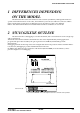

EVALUATION BOARD S5U1C62XXXE
S1C62 FAMILY EPSON VII-7
DEVELOPMENT TOOL REFERENCE MANUAL
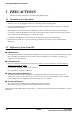
5 CABLE CONNECTION
This section describes how to connect the power cable to the S5U1C62xxxE, and the S5U1C62xxxE to
the ICE and the target system.
Note: Turn the power of all equipment off before connecting or disconnecting cables.
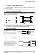
5.1 Connection to ICE (S5U1C62000H)
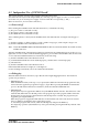
The S5U1C62xxxE is connected to the ICE by connecting the two interface cables (F1 and F5). Use
S5U1C62xxxE connectors F1 and F5 with the projections facing outwards. Use ICE connectors F1 and F5
with the projections facing inwards (cable side).
Figures 5.1.1 and 5.1.2 show the external view and connection diagram of the ICE interface cable.
ICE
F1
F5
S5U1C62xxxE
Red mark
2 1
50 49
2 1
50 49
:
:
:
:
:
:
:
:
:
:
:
:
:
:
:
:
:
:
:
:
ICE side S5U1C62xxxE side
Fig. 5.1.2 Connection diagramFig. 5.1.1 External view of the ICE interface cable
Note: The S5U1C62xxxE has an external power input connector for +5 V (VDD) and GND (VSS). Leave
these connectors unconnected when the S5U1C62xxxE is connected to the ICE.
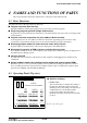
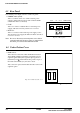
5.2 Power Cable Connection
When using the S5U1C62xxxE on its own, it
must be supplied with power (5 V DC, 3 A or
more) from an external source through the
power cable.
When the S5U1C62xxxE is connected to the
ICE, power is supplied by the ICE; therefore,
the power cable is not necessary. Disconnect
-
+
Connect to the
power connector
of the S5U1C62xxxE
Connect to the
external power
supply
Black
Red
Fig. 5.2.1 Connection of power cable pins
the power cable if it is already connected.
Figure 5.2.1 shows the connection of the power cable pins.
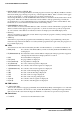
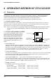
5.3 Connection to Target System
The I/O #0, I/O #1, LCD #0 and LCD #1
connectors are used to connect the
S5U1C62xxxE to the target system.
The signals output from the LCD #0 and
LCD #1 connectors are the same as those of
the actual IC at the function level. There-
fore, the S5U1C62xxxE may be connected to
the LCD of the target system without any
changes. The LCD contrast (LCD drive
voltage) is adjusted by the VADJ control.
Refer to the "S5U1C62xxxE Manual" for the
configuration and pins of the connectors.
S5U1C62xxxE
I/O #0, #1
LCD #0, #1
Front
LCD cable
I/O cable
I/O
LCD
Target
system
connector
connector
Fig. 5.3.1 Connection of target system