
Specifications


S1C62N82 TECHNICAL SOFTWARE EPSON II-25
CHAPTER 3: PERIPHERAL CIRCUITS (Special Use Output Ports)
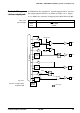
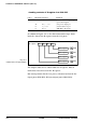
In addition to the regular DC, special output can be selected
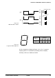
for output ports R10–R12, as shown in Table 3.4.2. Figure
3.4.1 shows the structure of output ports R10–R12 and MO.
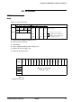
Pin Name When Special Output is Selected
R12 MO or ENV
R10 FOUT
Control of the spe-
cial use output port
Address
(0F4H)
FOUT
Data bus
R10
R11
R12
Mask option
Register
(R12)
Register
(R11)
Register
(R10)
MO
or ENV
MO
Register
(MELD)
Melody data
Fig. 3.4.1
Structure of output ports
R10–R12, MO
Table 3.4.2
Special output