
Specifications

I-50 EPSON S1C62N82 TECHNICAL HARDWARE
CHAPTER 4: PERIPHERAL CIRCUITS AND OPERATION (LCD Driver)
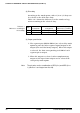
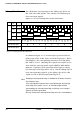
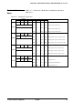
(2) Drive duty
According to the mask option, either 1/4 or 1/8 duty can
be selected as the LCD drive duty.
Table 4.6.1 shows the differences in the number of seg-
ments according to the selected duty.
Pins Used Maximum Number Frame Frequency
in Common of Segments (when fosc1 = 32 kHz)
1/4 COM0–3 168 (42 × 4) 32 Hz
1/8 COM0–7 304 (38 × 8) 32 Hz
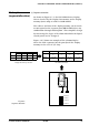
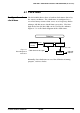
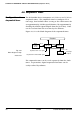
(3) Output specification
➀ The segment pins (SEG0–SEG41) are selected by mask
option in pairs for either segment signal output or DC
output (VDD and VSS binary output). When DC output
is selected, the data corresponding to COM0 of each
segment pin is output.
➁ When DC output is selected, either complementary
output or Pch open drain output can be selected for
each pin by mask option.
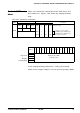
The pin pairs are the combination of SEG (2
*
n) and SEG (2
*
n +
1) (where n is an integer from 0 to 20).
Table 4.6.1
Differences according to
selected duty
Note
Duty