
User`s manual


10: DISPLAY CONFIGURATION
S1D13504 SERIES HARDWARE FUNCTIONAL EPSON 1-89
SPECIFICATION (X19A-A-002-17)
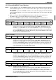
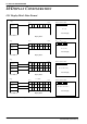
Figure 10-2 15/16 Bit-Per-Pixel Format Memory Organization
Note: 1. The Host-to-Display mapping described here assumes that a Little-Endian interface is being used.
2. For 8/15/16 bit-per-pixel formats, Rn, Gn, Bn represent the red, green, and blue color compo-
nents.
15-bpp:
R0
4
Host Address
Display Buffer
bit 7 bit 0
Panel Display
P0
P1 P2
P3
P4
P5 P6
P7
R0
3
R0
2
R0
1
R0
0
G0
4
G0
3
G0
2
G0
1
G0
0
B0
4
B0
3
B0
2
B0
1
B0
0
G1
2
G1
1
G1
0
B1
4
B1
3
B1
2
B1
1
B1
0
16-bpp:
R0
4
Host Address
Display Buffer
bit 7 bit 0
R0
3
R0
2
R0
1
R0
0
G0
5
G0
4
G0
3
G0
2
G0
1
G0
0
B0
4
B0
3
B0
2
B0
1
B0
0
R1
4
R1
3
R1
2
R1
1
R1
0
G1
5
G1
4
G1
3
G1
2
G1
1
G1
0
B1
4
B1
3
B1
2
B1
1
B1
0
5-6-5 RGB
5-5-5 RGB
R1
4
R1
3
R1
2
R1
1
R1
0
G1
4
G1
3
Byte 0
Byte 1
Byte 2
Byte 3
Byte 0
Byte 1
Byte 2
Byte 3
Panel Display
P0
P1 P2
P3
P4
P5 P6
P7
Pn = (Rn
4-0
, Gn
5-0
, Bn
4-0
)
TFT
Passive
Pn = (Rn
4-1
, Gn
5-2
, Bn
4-1
)
P
n = (Rn
4-0
, Gn
4-0
, Bn
4-0
)
TFT
Passive
Pn = (Rn
4-1
, Gn
4-1
, Bn
4-1
)