
User`s manual


2: PROGRAMMING THE S1D13504 REGISTERS
S1D13504 PROGRAMMING NOTES
EPSON
2-3
AND EXAMPLES (S19A-G-002-06)
2.2 Register Initialization
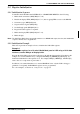
2.2.1 Initialization Sequence
To initialize the S1D13504 after POWER-ON or a HARDWARE RESET, do the following:
1. Enable the host interface (REG[1Bh] bit 7 = 0).
2. Disable the display FIFO (REG[23h] bit 7 = 1) after stopping FIFO accesses to the DRAM.
3. Set memory type (REG[01h] bit 0).
4. Set performance register (REG[22h]).
5. Set dual/single panel (REG[02h] bit 1).
6. Program all other registers as required.
7. Enable the display FIFO (REG[23h] bit 7 = 0).
8. Enable display.
Note:
The Half Frame Buffer does not actually start to access DRAM until step 5, therefore, this initialization
sequence will not cause any problems.
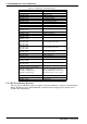
2.2.2 Initialization Example
This section presents an example of how to initialize the S1D13504 registers.
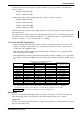
Example 1
Initialize the registers for a 16 color 640x480 dual passive LCD using a 16 bit data
interface; assume 2M byte of display buffer.
Program the S1D13504 registers in the following order with the data supplied. Note that for this
example, it is assumed that the arrays “unsigned char RED[16], GREEN[16], BLUE[16]” are
defined and initialized for the required colors. For example, RED[2], GREEN[2], and BLUE[2]
refer to the color components of pixel value 2.
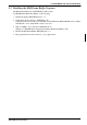
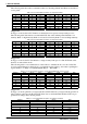
In addition, it is assumed that there is no external RAMDAC since only the LCD is being pro-
grammed. Consequently, the RAMDAC registers are not programmed.
For code examples, see Section 9,
“Sample Code”
on page 38.