
User`s manual


4: ADVANCED TECHNIQUES
2-18 EPSON S1D13504 PROGRAMMING NOTES
AND EXAMPLES (S19A-G-002-06)
4.3 Split Screen
Occasionally the need arises to display two distinct images on the display. For example, we may
want to write a game where the main play area will be rapidly updated and we want an unchanging
status display at the bottom of the screen.
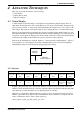
The Split Screen feature of the S1D13504 allows a programmer to set up a display for such an appli-
cation. The figure below illustrates setting up a 320x240 panel to have Image 1 displaying from scan
line 0 to scan line 99 and image 2 displaying from scan line 100 to scan line 239. Although this
example picks specific values, image 1 and image 2 can be shown as varying portions of the screen.
Figure 4-2 320x240 Single Panel For Split Screen
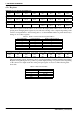
4.3.1 Registers
The other registers required for split screen operations, [10h] through [12h] (Screen 1 Display Start
Address) and [18h] (Pixel Panning Register), are described in Section 4.2 on page 16.
These two registers form a value known as the line compare. When the line compare value is equal
to or greater than the physical number of lines being displayed there is no visible effect on the dis-
play. When the line compare value is less than the number of physically displayed lines, display
operation works like this:
1. From the end of vertical non-display to the number of lines indicated by line compare the display
data will be from the memory pointed to by the Screen 1 Display Start Address.
2. After line compare lines have been displayed the display will begin showing data from Screen 2
Display Start Address memory.
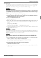
These three registers form the twenty bit offset to the first word in display buffer that will be shown
in the screen 2 portion of the display.
Scan Line 0
Image 1...
Scan Line 99
Scan Line 100
Image 2...
Scan Line 239
Screen 1 Display Line Count Register = 99 lines
REG[0E] Screen 1 Line Compare Register 0
Line Compare
Bit 7
Line Compare
Bit 6
Line Compare
Bit 5
Line Compare
Bit 4
Line Compare
Bit 3
Line Compare
Bit 2
Line Compare
Bit 1
Line Compare
Bit 0
REG[0F] Screen 1 Line Compare Register 1
n/a n/a n/a n/a n/a n/a
Line Compare
Bit 9
Line Compare
Bit 8
REG[13h] Screen 2 Display Start Address Register 0
Start Address
Bit 7
Start Address
Bit 6
Start Address
Bit 5
Start Address
Bit 4
Start Address
Bit 3
Start Address
Bit 2
Start Address
Bit 1
Start Address
Bit 0
REG[14h] Screen 2 Display Start Address Register 1
Start Address
Bit 15
Start Address
Bit 14
Start Address
Bit 13
Start Address
Bit 12
Start Address
Bit 11
Start Address
Bit 10
Start Address
Bit 9
Start Address
Bit 8
REG[15h] Screen 2 Display Start Address Register 2
n/a n/a n/a n/a
Start Address
Bit 19
Start Address
Bit 18
Start Address
Bit 17
Start Address
Bit 16