
User`s manual

4: BLOCK DESCRIPTION
1-6 EPSON S1D13504 SERIES HARDWARE FUNCTIONAL
SPECIFICATION (X19A-A-002-17)
4BLOCK DESCRIPTION
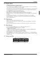
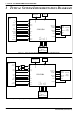
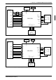
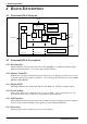
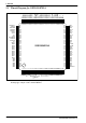
4.1 Functional Block Diagram
Figure 4-1 System Block Diagram Showing Datapaths
4.2 Functional Block Descriptions
4.2.1 Host Interface
The Host Interface block provides the means for the CPU/MPU to communicate with the display
buffer and internal registers, via one of the supported bus interfaces.
4.2.2 Memory Controller
he Memory Controller block arbitrates between CPU accesses and display refresh accesses as well
as generates the necessary signals to interface to one of the supported 16-bit memory devices (FPM-
DRAM or EDO-DRAM).
4.2.3 Display FIFO
The Display FIFO block fetches display data from the Memory Controller for display refresh.
4.2.4 Look-Up Table
The Look-Up Table block contains three 16 × 4 Look-Up Tables, one for each primary color. In
monochrome mode only one of these Look-Up Tables is selected and used.
4.2.5 LCD Interface
The LCD Interface block performs frame rate modulation for passive LCD panels. It also generates
the correct data format and timing control signals for various LCD and TFT panels.
4.2.6 Power Save
The Power Save block contains the power save mode circuitry.
LCD
Memory
Controller
16-bit FPM/EDO
DRAM
LCD
Clocks
Power Save
Register
CRTC
Look-Up
I/F
CPU / MPU
Host
I/F
DAC
CPU
R/W
Bus Clock Memory Clock Pixel Clock
Display
FIFO
Control
DAC
Data
Table