
User`s manual


4: CPU/BUS INTERFACE CONNECTOR PINOUTS
S5U13504P00C REV1.0 ISA BUS EVALUATION BOARD
EPSON
4-5
USER’S MANUAL (S19A-G-004-05)
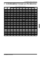
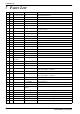
Table 4-2 CPU/BUS Connector (H2) Pinout
Connector
Pin No.
Comments
1 Connected to AB0 of the S1D13504
2 Connected to AB1 of the S1D13504
3 Connected to AB2 of the S1D13504
4 Connected to AB3 of the S1D13504
5 Connected to AB4 of the S1D13504
6 Connected to AB5 of the S1D13504
7 Connected to AB6 of the S1D13504
8 Connected to AB7 of the S1D13504
9 Ground
10 Ground
11 Connected to AB8 of the S1D13504
12 Connected to AB9 of the S1D13504
13 Connected to AB10 of the S1D13504
14 Connected to AB11 of the S1D13504
15 Connected to AB12 of the S1D13504
16 Connected to AB13 of the S1D13504
17 Ground
18 Ground
19 Connected to AB14 of the S1D13504
20 Connected to AB15 of the S1D13504
21 Connected to AB16 of the S1D13504
22 Connected to AB17 of the S1D13504
23 Connected to AB18 of the S1D13504
24 Connected to AB19 of the S1D13504
25 Ground
26 Ground
27 5 volt supply
28 5 volt supply
29 Connected to RD/WR# of the S1D13504
30 Connected to BS# of the S1D13504
31 Connected to BUSCLK of the S1D13504
32 Connected to RD# of the S1D13504
33 Connected to AB20 of the S1D13504
34 Not connected