
User`s manual


6: TECHNICAL DESCRIPTION
S5U13504P00C REV1.0 ISA BUS EVALUATION BOARD EPSON 4-9
USER’S MANUAL (S19A-G-004-05)
6.10 Power Save Modes
The S1D13504 supports one hardware and one software suspend Power Save Mode.
The hardware suspend mode is not supported by the S5U13504P00C.
The software suspend mode is controlled by the utility 1354PWR Software Suspend Power
Sequencing.
6.11 Core VDD Power Supply
An independent fixed 3.3V power supply for Core VDD is provided. A National LP2960AIN-3.3
voltage regulator is used for the power supply and is capable of supplying 500mA @ 3.3V.
6.12 IO VDD Power Supply
The IO VDD voltage is selectable between 3.3V and 5.0V through jumper JP2. For the 5.0V host bus
interface, select IO VDD at 5.0V, and for the 3.3V host bus interface, select IO VDD at 3.3V.
Refer to Table 2-3, “Jumper Settings,” on page 2.
6.13 Adjustable LCD Panel Negative Power Supply
Most monochrome passive LCD panels require a negative power supply to provide between -18V
and -23V (Iout = 45mA). For ease of implementation, such a power supply has been provided as an
integral part of this design. The signal VLCD can be adjusted by R37 to supply an output voltage
from -14V to -23V and is enabled/disabled by the S1D13504 control signal LCDPWR.
Determine the panel’s specific power requirements and set the potentiometer accordingly before
connecting the panel.
6.14 Adjustable LCD Panel Positive Power Supply
Most passive LCD passive color panels and most single monochrome 640 x 480 passive LCD panels
require a positive power supply to supply between +23V and +40V (Iout = 45mA). For ease of imple-
mentation, such a power supply has been provided as an integral part of this design. The signal
VDDH can be adjusted by R31 to provide an output voltage from +23V to +40V and is enabled/dis-
abled by the S1D13504 control signal LCDPWR.
Determine the panel’s specific power requirements and set the potentiometer accordingly before
connecting the panel.
6.15 CPU/Bus Interface Header Strips
All of the CPU/Bus interface pins of the S1D13504 are connected to the header strips H1 and H2 for
easy interface to a CPU/Bus other than the ISA bus.
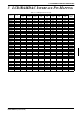
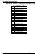
Refer to Table 4-1, “CPU/BUS Connector (H1) Pinout,” on page 4 and Table 4-2, “CPU/BUS Con-
nector (H2) Pinout,” on page 5 for specific settings.
Note: These headers only provide the CPU/BUS interface signals from the S1D13504. When another host
bus interface is selected through MD[3:1] configuration, appropriate external decode logic MUST be
used to access the S1D13504. See the section “Host Bus Interface Pin Mapping” of the “S1D13504
Hardware Functional Specification,” document number S19A-A-002-xx.
6.16 Schematic Notes
The following schematics are for reference only and may not reflect actual implementation. Please
request updated information before starting any hardware design.