
User`s manual


3: INTERFACING TO THE PC CARD BUS
APPLICATION NOTES (S19A-G-005-05) EPSON 5-15
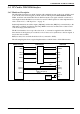
3.3 S1D13504 Host Bus Interface
This section is a summary of the host bus interface modes available on the S1D13504 and offers
some detail on the Generic MPU host bus interface used to implement the interface to the PC Card
bus.
3.3.1 Bus Interface Modes
The S1D13504 implements a 16-bit interface to the host microprocessor which may operate in one
of several modes compatible with most of the popular embedded microprocessor families. Four host
bus interface modes are supported:
• Hitachi SH-3.
• Motorola MC68000 (using Upper Data Strobe/Lower Data Strobe).
• Motorola MC68020/MC68030/MC683xx (using Data Strobe/DSACKx).
• Generic MPU.
The S1D13504 latches MD3 through MD1 to allow selection of the host bus interface on the rising
edge of RESET#. After releasing reset, the bus interface signals assume their selected configuration.
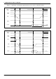
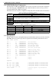
The following table shows the functions of each host bus interface signal.
Two other configuration options (MD[5:4]) are also made at the time of hardware reset:
• endian mode setting (big endian or little endian).
• polarity of the WAIT# signal.
The capability to select the endian mode independent of the host bus interface offers more flexibility
in configuring the S1D13504 with other CPUs.
For details on configuration, refer to the “S1D13504 Hardware Functional Specification”, document
number S19A-A-002-xx.
Table 3-1 Host Bus Interface Pin Mapping
S1D13504
Pin Names
SH-3 MC68K Bus 1 MC68K Bus 2 Generic MPU
AB[20:1] A[20:1] A[20:1] A[20:1] A[20:1]
AB0 A0 LDS# A0 A0
DB[15:0] D[15:0] D[15:0] D[31:16] D[15:0]
WE1# WE1# UDS# DS# WE1#
M/R# External Decode External Decode External Decode External Decode
CS# CSn# External Decode External Decode External Decode
BUSCLK CKIO CLK CLK BCLK
BS# BS# AS# AS# Connect to IO V
DD
RD/WR# RD/WR# R/W# R/W# RD1#
RD# RD# Connect to IO VDD SIZ1 RD0#
WE0# WE0# Connect to IO VDD SIZ0 WE0#
WAIT# WAIT# DTACK# DSACK1# WAIT#
RESET# RESET# RESET# RESET# RESET#