
User`s manual


4: INTERFACING TO THE MOTOROLA MPC821 MICROPROCESSOR
5-28 EPSON APPLICATION NOTES (S19A-G-005-05)
4.3.2 Generic Bus Interface Mode
Generic Bus Interface Mode is the most general and least processor-specific interface mode on the
S1D13504. Although the Power PC bus is similar in many respects to the M68K bus, the generic bus
interface mode was chosen for this interface due to the simplicity of its timing and compatibility
with the control signals available from the MPC821’s General-Purpose Chip Select Module.
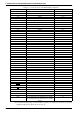
The interface requires the following signals:
• BUSCLK is a clock input which synchronizes transfers between the host CPU and the S1D13504.
It is separate from the pixel clock (CLKI) and is typically driven by the host CPU system clock.
• The address inputs AB0 through AB20, and the data bus DB0 through DB15, connect directly to
the CPU address and data bus, respectively. On 32-bit big endian architectures such as the Power
PC, the data bus would connect to the high-order data lines; on little endian hosts, or 16-bit big
endian hosts, they would connect to the low-order data lines. The hardware engineer must ensure
that MD4 selects the proper endian mode upon reset.
• Chip Select (CS#) is driven by decoding the high-order address lines to select the proper IO or
memory address space.
• M/R# is driven high for memory accesses, or low for S1D13504 register accesses. On CPUs
which implement memory-mapped IO, this pin is typically tied to an address line; on CPUs with
separate IO spaces, this pin is typically driven by control logic from the CPU.
• WE0# and WE1# are write enables for the low-order and high-order bytes, respectively, to be
driven low when the host CPU is writing data to the S1D13504. These must be generated by exter-
nal decode hardware based upon the control outputs from the host CPU.
• RD# and RD1# are read enables for the low-order and high-order bytes, respectively, to be driven
low when the host CPU is reading data from the S1D13504. These must be generated by external
decode hardware based upon the control outputs from the host CPU.
• WAIT# is a signal which is output from the S1D13504 to the host CPU which indicates when data
is ready (read cycle) or accepted (write cycle) on the host bus. Since host CPU accesses to the
S1D13504 may occur asynchronously to the display update, it is possible that contention may
occur in access to the 13504 internal registers and/or refresh memory. The WAIT# line resolves
these contentions by forcing the host to wait until the resource arbitration is complete. This signal
may be either active high or active low, depending upon the state of MD5 at reset.
• The Bus Status (BS#) signal is unused in general purpose bus mode, and should be tied high (con-
nected to IO VDD).