
User`s manual


8: REGISTERS
1-70 EPSON S1D13504 SERIES HARDWARE FUNCTIONAL
SPECIFICATION (X19A-A-002-17)
8.2.4 Display Configuration Registers
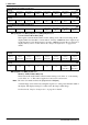
bits 6–5 Simultaneous Display Option Select Bits [1:0]
These bits are used to select one of four different simultaneous display mode options:
Normal, Line Doubling, Interlace, or Even Scan Only. The purpose of these modes is to
manipulate the vertical resolution of the image so that it fits on both CRT, typically 640 x
480, and LCD. The following gives descriptions of the four modes using a 640 x 480 CRT
as an example:
Note: 1. Line doubling option is not supported with dual panel.
2. Dual Panel Considerations
When configured for a dual panel LCD and using Simultaneous Display,
the Half Frame Buffer Disable, REG[1Bh] bit 0, must be set to 1. This will result in a
lower contrast on the LCD panel, which then may require adjustment.
Normal - the image is the same on both displays, i.e. 640 x 240. CRT parameters deter-
mine the LCD image. The LCD image will appear to be washed out due to the 1/525 duty
cycle of the CRT.
Line Doubling - each line is sent to the CRT twice, giving a 640 x 480 image which has a
long aspect ratio. The image on the LCD has each line sent twice but only one FPLINE.
This gives a duty cycle of 2/525, which is very close to the LCD only mode duty cycle of
1/242, so the image on the LCD will have almost the same contrast as that of a single
LCD.
Interlace - odd frames receive odd scan lines and even frames receive even scan lines.
The 640 x 480 image on the CRT will be normal while the image on the 640 x 240 LCD
will appear to be squashed, though text will be readable.
Even Scan Only - the 640 x 480 image on the CRT is normal. The LCD (640 x 240) only
receives the even scan lines. The image on the LCD does not flicker, but it may be hard to
read text.
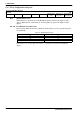
bits 4–2 Number of Bits-Per-Pixel Select Bits [2:0]
These bits select the number of bits-per-pixel (bpp) for the displayed data.
Note: 15 and 16-bpp modes bypass the LUT and are supported as 12-bpp on passive panels
and 15/16-bpp on TFT panels. These modes are not supported on CRT. See Figure 10-2,
“15/16 Bit-Per-Pixel Format Memory Organization,” on page 89 for a description of passive
panel support.
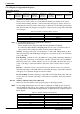
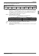
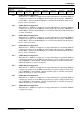
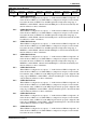
Display Mode Register
REG[0Dh] RW
n/a
Simultaneous
Display Option
Select Bit 1
Simultaneous
Display Option
Select Bit 0
Number Of
Bits/Pixel
Select Bit 2
Number Of
Bits/Pixel
Select Bit 1
Number Of
Bits/Pixel
Select Bit 0
CRT Enable LCD Enable
Table 8-6 Simultaneous Display Option Selection
Simultaneous Display Option Select Bits [1:0] Simultaneous Display Option
00 Normal
01 Line Doubling
10 Interlace
11 Even Scan Only
Table 8-7 Number of Bits-Per-Pixel Selection
Number of Bits-Per-Pixel Select Bits [2:0] Number of Bits-Per-Pixel
000 1
001 2
010 4
011 8
100 15
101 16
110–111 Reserved