
User`s manual


8: REGISTERS
1-76 EPSON S1D13504 SERIES HARDWARE FUNCTIONAL
SPECIFICATION (X19A-A-002-17)
8.2.7 Miscellaneous Registers
bit 7 Host Interface Disable
This bit must be programmed to 0 to enable the Host Interface. This bit goes high on
reset. When this bit is high, all memory and all registers except REG[1Ah] (read-only),
REG[28h] through REG[2Fh], and REG[1Bh] are inaccessible.
bit 0 Half Frame Buffer Disable
This bit is used to disable the half frame buffer.
When this bit = 1, the Half Frame Buffer is disabled. When this bit = 0, the Half Frame
Buffer is enabled. When a single panel is selected, the Half Frame Buffer is automatically
disabled and this bit has no hardware effect.
The Half Frame Buffer is needed to fully support dual panels. Disabling the Half Frame
Buffer reduces memory bandwidth requirements and increases the supportable pixel
clock frequency, but results in reduced contrast on the LCD panel. This mode is not nor-
mally used except in special
circumstances such as simultaneous display on a CRT and dual panel LCD. See Section
11.2 on page 92 for details.
Note: The Half Frame Buffer should be disabled only when idle. The Half Frame Buffer is idle
during vertical non-display periods (i.e. when REG[0Ah] bit 7 = 1), or while in suspend
mode. For programming information, see “S1D13504 Programming Notes and Examples”,
document number S19A-G-002-xx.
REG[1Ch] bits 7–0, REG[1Dh] bits 7–0
MD[15:0] Configuration Status
These are read-only status bits for the MD[15:0] pins configuration status at the rising
edge of RESET#.
See Table 5-8, “Summary of Power On / Reset Options,” on page 16.
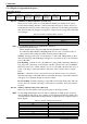
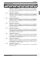
Miscellaneous Disable Register
REG[1Bh] RW
Host Interface
Disable
n/a n/a n/a n/a n/a n/a
Half Frame
Buffer Disable
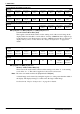
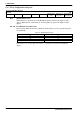
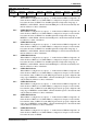
MD Configuration Readback Register 0
REG[1Ch] RO
MD7 Status MD6 Status MD5 Status MD4 Status MD3 Status MD2 Status MD1 Status MD0 Status
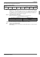
MD Configuration Readback Register 1
REG[1Dh] RO
MD15 Status MD14 Status MD13 Status MD12 Status MD11 Status MD10 Status MD9 Status MD8 Status