
User`s manual


8: REGISTERS
S1D13504 SERIES HARDWARE FUNCTIONAL EPSON 1-77
SPECIFICATION (X19A-A-002-17)
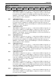
bit 7 GPIO7 Pin IO Configuration
When this bit = 1, GPIO7 is configured as an output. When this bit = 0 (default), GPIO7 is
configured as an input. Note the MD8 pin must be high at the rising edge of RESET# to
enable GPIO7, otherwise the DACWR# pin is controlled automatically and this bit will
have no effect on hardware.
bit 6 GPIO6 Pin IO Configuration
When this bit = 1, GPIO6 is configured as an output. When this bit = 0 (default), GPIO6 is
configured as an input. Note the MD8 pin must be high at the rising edge of RESET# to
enable GPIO6, otherwise the DACP0 pin is controlled automatically and this bit will have
no effect on hardware.
bit 5 GPIO5 Pin IO Configuration
When this bit = 1, GPIO5 is configured as an output. When this bit = 0 (default), GPIO5 is
configured as an input. Note the MD8 pin must be high at the rising edge of RESET# to
enable GPIO5, otherwise the BLANK# pin is controlled automatically and this bit will
have no effect on hardware.
bit 4 GPIO4 Pin IO Configuration
When this bit = 1, GPIO4 is configured as an output. When this bit = 0 (default), GPIO4 is
configured as an input. Note the MD8 pin must be high at the rising edge of RESET# to
enable GPIO4, otherwise the DACRD# pin is controlled automatically and this bit will
have no effect on hardware.
bit 3 GPIO3 Pin IO Configuration
When this bit = 1, GPIO3 is configured as an output. When this bit = 0 (default), GPIO3 is
configured as an input. Note the MD[7:6] pins must be properly configured at the rising
edge of RESET# to enable GPIO3, otherwise the MA9 pin is controlled automatically
and this bit will have no effect on hardware.
bit 2 GPIO2 Pin IO Configuration
When this bit = 1, GPIO2 is configured as an output. When this bit = 0 (default), GPIO2 is
configured as an input. Note the MD[7:6] pins must be properly configured at the rising
edge of RESET# to enable GPIO2, otherwise the MA11 pin is controlled automatically
and this bit will have no effect on hardware.
bit 1 GPIO1 Pin IO Configuration
When this bit = 1, GPIO1 is configured as an output. When this bit = 0 (default), GPIO1 is
configured as an input. Note the MD[7:6] pins must be properly configured at the rising
edge of RESET# to enable GPIO1, otherwise the MA10 pin is controlled automatically
and this bit will have no effect on hardware.
bit 0 GPIO0 Pin IO Configuration
When this bit = 1, GPIO0 is configured as an output. When this bit = 0 (default), GPIO0 is
configured as an input.
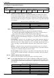
GPIO Configuration Register 0
REG[1Eh] RW
GPIO7 Pin
IO Config.
GPIO6 Pin
IO Config.
GPIO5 Pin
IO Config.
GPIO4 Pin
IO Config.
GPIO3 Pin
IO Config.
GPIO2 Pin
IO Config.
GPIO1 Pin
IO Config.
GPIO0 Pin
IO Config.